GD&T Datum: Definition, Types, Symbols, and Datum Reference Frame
19 min
- What Is a Datum in GD&T?
- Common GD&T Datum Geometries
- How Are Datum Features Identified on Engineering Drawings?
- How Does a Datum Reference Frame Work?
- How Are Datums Used in GD&T Callouts and Inspection?
- How Are Datums Selected for CNC Machining?
- Datums FAQs
- Conclusion About Datums
Key Takeaways
- A datum in GD&T is a theoretically exact reference used to locate or orient other features on a part. It is not the physical surface itself.
- A datum feature is the physical feature identified on the part and used to establish a datum. The datum itself is the theoretically exact geometric reference derived from that feature.
- Datums become especially important when several features have to work together. A hole pattern, bearing bore, mounting face, or mating surface may need to establish the reference from which other features are located.
- The order of datum references matters. A primary, secondary, and tertiary datum progressively constrain the part and establish a repeatable datum reference frame.
- For CNC machining, a good datum scheme should make sense for the part's function, machining setup, workholding, and inspection. A datum that looks convenient on a drawing but is difficult to establish consistently on the machine or CMM can create problems later.
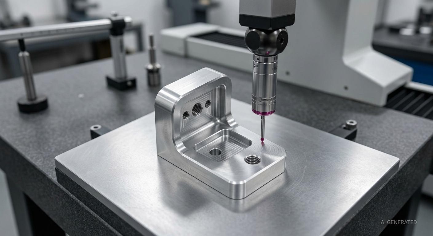
CNC-machined component being inspected against a primary datum surface
A CNC machine can hold a dimension very accurately and still make a part that does not assemble correctly.
Usually, the problem is not the size of one feature. It is the relationship between several features.
Consider a mounting plate with four holes. Each hole might be within its size tolerance. The plate can still fail during assembly if the hole pattern is shifted, rotated, or referenced from the wrong surface.
That is where datums come in.
GD&T uses datums to establish a common reference system for locating and orienting features. Instead of treating every dimension as an independent measurement, the drawing can tell the manufacturer and inspector how important features relate to a defined reference.
ASME Y14.5 is the primary U.S. standard for the language and rules of GD&T, including datum references and datum reference frames.
The terminology can be confusing at first because three things are closely connected but are not the same:
- datum feature
- datum
- datum reference frame
Once you separate those three ideas, most datum callouts become much easier to read.
What Is a Datum in GD&T?
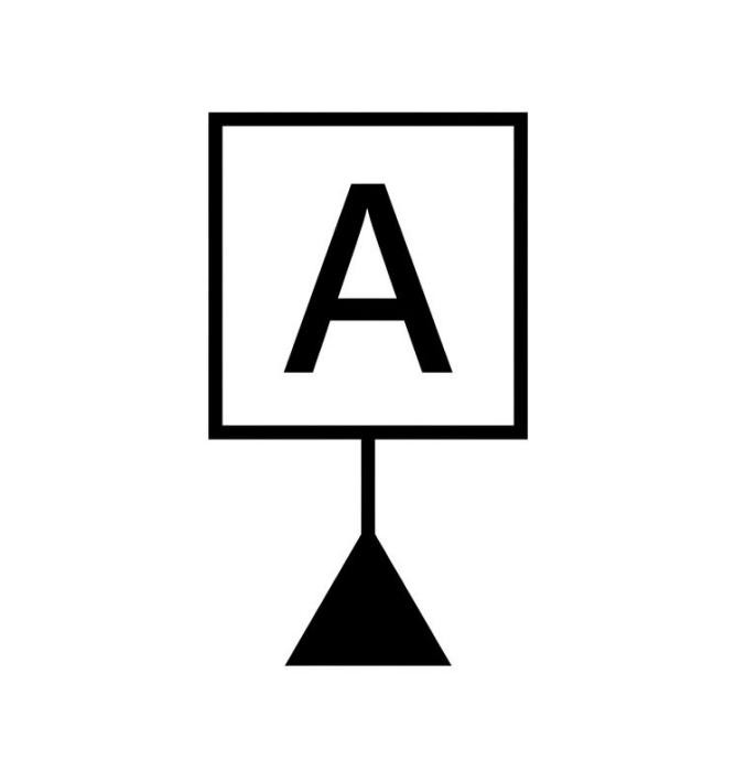
Datum symbol
A datum is a theoretically exact reference used to establish the location or orientation of features on a part. Under ASME Y14.5, a datum may be established as a theoretically exact point, axis, or plane, depending on the datum feature and the required geometric relationship.
A simple example is a flat mounting surface.
The actual aluminum or steel surface on the manufactured part is never perfectly flat. It has some amount of form variation. GD&T does not treat that imperfect surface itself as the theoretical reference. Instead, the datum is an ideal plane derived from the datum feature.
In manufacturing and inspection, a physical datum feature simulator or a mathematical datum construction can be used to establish the reference needed to reproduce the theoretical datum.
This distinction is important because a manufactured part is always imperfect. Inspection needs a consistent reference against which that imperfect part can be evaluated.
For a broader introduction to how datums, feature control frames, and tolerance zones work together in CNC drawings, see our guide to GD&T in CNC machining.
In practical terms, a datum is the reference from which another feature's location, orientation, or relationship is controlled.
For example, suppose a rectangular CNC-machined plate has a bottom mounting surface identified as Datum A. A hole located 25 mm from that surface is not simply 25 mm away from an arbitrary edge. Its location is defined relative to the datum system established by the drawing.
The datum makes the intended feature relationship explicit for both manufacturing and inspection.
Datum vs. Datum Feature
This is one of the most common points of confusion in GD&T.
A datum feature is the actual physical feature on the part.
A datum is the theoretically exact reference derived from that feature.
So if a flat surface on a machined part is identified as Datum A:
- The datum feature itself still has size, form, orientation, and surface variation; those variations are not automatically ignored when the datum feature is controlled elsewhere on the drawing.
The same idea applies to a cylindrical feature. The physical bore can be the datum feature, while its theoretically derived axis becomes the datum.
Common GD&T Datum Geometries
The type of datum depends on the geometry of the datum feature.
A broad flat surface commonly establishes a datum plane. A cylindrical feature can establish a datum axis. Other geometries can establish center planes, lines, or points.
Classifying the datum by the feature geometry is more useful than memorizing names. A planar face generally establishes a plane, while a cylindrical feature commonly establishes an axis.
Planar Datums
A planar datum is established from a planar datum feature.
Imagine a machined rectangular block resting on a surface plate. The bottom face can establish a datum plane.
That plane can then provide the reference for height, orientation, or location requirements elsewhere on the part.
Planar datums are extremely common because many mechanical parts have functional mounting surfaces. A base, flange, housing face, or fixture surface can all serve this role.
A planar datum also plays a major role in constraining a part during inspection. Once the part is brought into contact with a simulated primary datum plane, three degrees of freedom are constrained: one translation and two rotations.
Datum Axes and Center Planes
Not every important feature is a flat surface.
A hole, bore, shaft, or other cylindrical feature can establish a datum axis. The axis is theoretical, even though the physical cylindrical feature is what the inspector actually measures.
This is useful when the function of the part revolves around a centerline.
For example, a bearing bore may establish a datum axis while other holes, pockets, or cylindrical features are located relative to that axis.
Center planes work in a similar way for certain features and feature-of-size relationships. They are useful when the functional reference is the center of a feature rather than one of its physical surfaces.
The resulting datum can therefore describe something that is not directly visible on the physical part.
Datum Points and Center Planes
Some datum schemes use a theoretical point or center plane when a planar surface or cylindrical axis does not adequately represent the functional relationship that needs to be controlled.
A datum point represents a theoretically exact location used as a reference in an applicable datum scheme. A center plane can likewise serve as the theoretical reference derived from an appropriate datum feature when the center of a feature or feature-of-size relationship is functionally important.
These applications are less common in everyday CNC drawings than planar and cylindrical datum references, but the same principle applies: the datum is the theoretically exact reference, while the datum feature is the physical feature used to establish it.
How Are Datum Features Identified on Engineering Drawings?
Once you know what a datum is, the symbol on the drawing becomes easier to interpret.
Under ASME Y14.5, a datum feature is identified by a datum feature symbol containing a datum letter in a rectangular frame and connected to the applicable physical feature on the drawing.
The datum letter, such as A, B, or C, identifies the datum feature and is referenced later in feature control frames to establish the applicable datum precedence.
That letter is then used in feature control frames when another feature is controlled relative to that datum.
Datum Feature Symbols on Surfaces
When a datum feature symbol points to a planar surface, that surface becomes the physical datum feature.
For example, a rectangular mounting face might be identified as Datum A.
The resulting datum is the theoretically exact plane derived from that physical surface.
The location of the symbol matters. It tells you which feature is being identified as the datum feature.
This is particularly important on drawings with several similar surfaces. Moving the symbol to a different surface can change the entire datum reference scheme.
Datum Feature Symbols on Features of Size
A datum feature does not have to be a simple flat surface.
A hole, shaft, slot, or other feature of size can serve as a datum feature when the design requires its axis, center plane, or other derived reference.
For example, a precision bore may establish a datum axis used to locate another hole pattern.
The physical bore will contain some size and form variation. The datum axis is the theoretical reference derived from that feature.
A pattern of features can also serve as a datum feature when the function of the part depends on the pattern as a whole. In that case, the datum is established from the defined relationship of the multiple features rather than from a single hole or bore.
Datum Target Symbols and When They Are Used
Sometimes an entire surface is not suitable for establishing a datum.
This is common with large, irregular, flexible, cast, forged, or sheet metal parts where using the entire surface could produce an unrealistic or unstable reference.
Datum targets identify specific areas used to establish the datum.
A datum target may define a point, line, or limited area that contacts the datum simulator.
The idea is simple: instead of assuming the entire physical surface establishes the reference, the drawing tells inspection or tooling which portions of the feature are intended to establish it.
Datum targets become particularly useful when the functional or assembly condition of the part cannot be represented well by simply contacting an entire surface.
A Practical Note for CNC Manufacturing
A datum callout also affects how a CNC shop thinks about the part.
A drawing datum feature may also be used as a locating reference during CNC setup when that choice matches the part's functional requirements and fixture strategy. The drawing datum and the machine work coordinate system are related concepts, but they are not automatically the same reference.
That is why drawing datums should not be selected in isolation from manufacturing.
Working with a CNC drawing that includes datum references or GD&T callouts? Upload the 3D CAD model and 2D drawing for a CNC machining quote. JLCCNC can review the drawing requirements together with the machining and inspection considerations.

Precision CNC Machining Service
Professional manufacturing, fast turnaround, and quality assurance.
How Does a Datum Reference Frame Work?

primary, secondary, and tertiary datums establishing a GD&T datum reference frame
A datum by itself does not completely locate a part.
A datum reference frame (DRF) is the reference framework established from specified datum features in their stated order of precedence. For the conventional planar case, it consists of three mutually perpendicular datum planes that establish the basis for dimensioning and tolerancing.
Think of it as the part's agreed-upon reference system.
A manufactured part can translate in three directions and rotate around three axes. These are its six degrees of freedom.
The datum reference frame progressively removes those freedoms so the part can be located and inspected in a repeatable way.
Primary, Secondary, and Tertiary Datums
The first datum in a reference frame is the primary datum.
The second is the secondary datum.
The third is the tertiary datum.
The primary datum establishes the first constraint relationship between the part and the datum reference frame. The secondary datum then constrains the remaining degrees of freedom without overriding the primary relationship. The tertiary datum completes the required constraint for that reference frame.
This is often explained using the familiar 3-2-1 concept.
For a simple rectangular part:
- Datum A may be the bottom surface.
- Datum B may be one side surface.
- Datum C may be an end surface.
The three together establish a complete reference frame.
But there is no rule saying every part must use three planar surfaces. The actual datum scheme depends on the geometry and functional requirements.
How Datums Constrain Degrees of Freedom
The six degrees of freedom are:
- translation along X
- translation along Y
- translation along Z
- rotation about X
- rotation about Y
- rotation about Z
In a conventional datum reference frame based on three planar datum features, the primary datum constrains three degrees of freedom, the secondary datum constrains two additional degrees of freedom, and the tertiary datum constrains the remaining one. Other datum feature geometries can produce different constraint patterns.
That is the familiar case, not a universal recipe for every GD&T drawing. Cylindrical datum features, patterns, datum targets, and other configurations can constrain the part differently.
The important question is always: what movement is still possible after each datum has been established?
How Datum Feature Simulators Establish the Reference Frame
Inspection does not physically measure a theoretical datum because the datum itself is an ideal geometric reference. Instead, the datum is established by simulating or mathematically constructing the applicable datum relationship from the measured datum feature.
A planar datum can be physically simulated with a controlled surface such as a surface plate or fixture surface. A cylindrical datum may be established with a pin, mandrel, or other suitable simulator, while a CMM can construct the corresponding datum axis mathematically from measured feature data.
During physical setup, the datum features may contact fixture or gage elements in datum precedence order. During CMM inspection, the same datum precedence is established by probing the specified features and constructing the corresponding datum elements mathematically.
Once the reference frame is established, the controlled features can be measured relative to it.
This is one reason datum selection matters so much. The drawing defines the datum relationships that inspection must reproduce when evaluating features controlled to that datum reference frame.
How Are Datums Used in GD&T Callouts and Inspection?
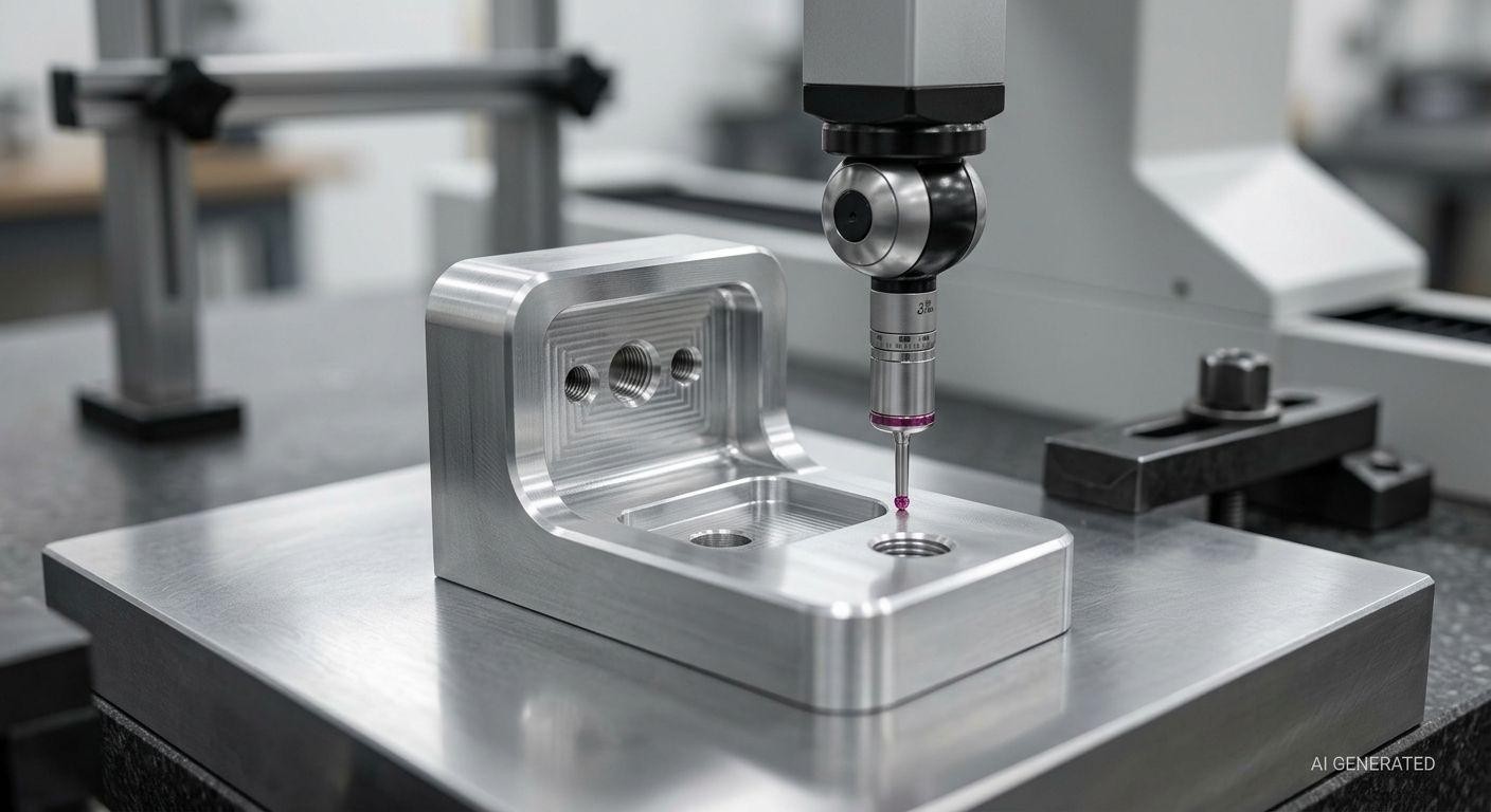
CMM inspection of a CNC-machined aluminum part using a datum surface
Datums become useful when a geometric requirement depends on the relationship between features.
A flatness callout, for example, does not need a datum because it controls the form of one surface by itself.
Position, perpendicularity, parallelism, and many other controls often need a datum because their meaning depends on orientation or location relative to another feature.
Datum References in Feature Control Frames
A feature control frame can reference one or more datums.
Consider a hole pattern controlled for position relative to A, B, and C.
The position tolerance does not exist in isolation. The hole pattern is being located inside the reference frame established by those datums.
The order of A, B, and C tells inspection which datum feature has precedence.
That same order also communicates design intent to manufacturing.
The datum sequence therefore becomes part of the tolerance scheme, not just a convenient labeling system.
Basic Dimensions Within a Datum Reference Frame
Basic dimensions define theoretically exact locations.
They are often used with GD&T to establish the theoretically exact location of a feature inside the datum reference frame, while the geometric tolerance defines how far the manufactured feature may vary from that exact location.
This is why basic dimensions often appear around hole patterns and feature locations in GD&T drawings.
The basic dimension establishes the intended geometry. The position or other geometric tolerance establishes the allowable variation.
Which GD&T Controls Require a Datum?
Not every GD&T control needs a datum.
Form controls such as flatness, straightness, circularity, and cylindricity evaluate the feature relative to itself and do not require a datum reference. Orientation controls such as parallelism, perpendicularity, and angularity use datum references to define the required orientation. Position commonly uses a datum reference frame to control feature location, while profile may be specified with or without datums depending on whether the requirement also controls orientation and location.
Datum-Based CMM Alignment
A CMM can construct a datum reference frame mathematically from measured features.
The CMM measures the specified datum features and establishes the applicable datum reference frame according to the drawing's datum precedence. The controlled features are then evaluated within that reference frame.
This is why a CMM result can show a hole's position relative to A, B, and C rather than simply reporting the hole's raw X, Y, and Z coordinates.
The alignment is part of the measurement.
For more on how CMMs establish coordinate systems, measure GD&T relationships, and verify CNC-machined parts, see our guide to CMM inspection.
How Are Datums Selected for CNC Machining?
Datum selection gets much more useful when you stop thinking about it as a drawing exercise.
The best datum is usually tied to something the part actually needs.
- What surface does the part sit on?
- What feature locates it during assembly?
- Which bore controls the rotating components?
- Which face does the mating component contact?
- How will the part be held during machining?
- How will the inspector establish the same reference later?
Those questions usually lead to a more practical datum scheme.
Functional and Assembly Requirements
Start with how the part works.
Suppose you are machining a gearbox housing. One face bolts to another housing, while a bore carries a bearing.
The mounting face and bearing bore are likely more important to the part's function than an arbitrary outside edge.
Those functional features may therefore be better datum candidates.
This approach helps prevent a common mistake: selecting datums because they are easy to dimension from rather than because they represent how the part actually locates and functions.
A good GD&T scheme should describe design intent, not simply make the drawing look organized.
Machining Setup and Workholding
The manufacturing setup matters too.
If Datum A is a large flat face, it may be easy to place that face against a fixture or machine table.
If Datum B is a side face, it may then be possible to locate the part against a stop.
That creates a machining setup that resembles the reference system on the drawing.
A datum scheme should be practical to establish on the machine as well as meaningful in the finished assembly. Fixture access, locating stability, and setup repeatability therefore need to be considered when the datum features are selected.
For CNC machining, workholding, locating, and setup repeatability can directly affect how consistently those datum relationships are produced.
Inspection and Multi-Operation Consistency
When a part is re-established from different locating features between CNC operations, the setup creates a new locating chain. Any variation in those features can shift or rotate the part relative to the functional datum, making the final relationship between critical features harder to control.
Where the process depends on a permanent functional datum, it is generally advantageous to establish that datum feature early enough in the process that subsequent operations can reference it without substantially changing its geometry.
For example, a hole pattern machined in one setup and a mating bore machined in another may need to share a functional reference. Re-establishing that relationship from unrelated surfaces can make the final assembly relationship harder to control.
A consistent datum strategy helps bridge machining and inspection.
The same drawing datum features can then be used as the common reference basis for machining setup planning and CMM inspection, even though the physical locating method may differ between production and inspection.
That is one of the practical strengths of GD&T. The drawing is not only describing what the finished part should look like. It is describing relationships that can be reproduced during manufacturing and measurement.
A datum scheme is much easier to manufacture when the drawing, machining setup, and inspection plan all point to the same functional references.
JLCCNC can review CNC machining drawings with dimensional tolerances, GD&T callouts, datum references, and inspection requirements before production.
Upload your CAD model and 2D drawing to get a CNC machining quote and let the manufacturing requirements be reviewed together.
Precision CNC Machining Service
Professional manufacturing, fast turnaround, and quality assurance.
Datums FAQs
What Is the Difference Between a Datum and a Datum Feature?
A datum feature is the real physical feature on the manufactured part. A datum is the theoretically exact reference derived from that feature.
For example, a machined flat surface can be the datum feature, while the theoretically exact plane derived from it is the datum.
Can a Hole Be Used as a Datum Feature?
Yes. A hole can be identified as a datum feature when its derived axis is useful as a functional reference. The same principle applies to other features of size, including shafts and certain slots.
A hole pattern can also serve as a datum feature in an appropriate GD&T scheme.
What Is the Difference Between a Datum and a Datum Reference Frame?
A datum is one theoretical reference, such as a plane or axis.
A datum reference frame is the complete reference system established by the specified datum sequence.
You can think of the datum as one reference element and the DRF as the coordinate framework created from the relevant datums.
What Are Primary, Secondary, and Tertiary Datums?
They describe datum precedence.
The primary datum is established first. The secondary datum is established next while maintaining the primary relationship. The tertiary datum is established last.
In a common three-plane setup, the primary constrains three degrees of freedom, the secondary two, and the tertiary one.
What Is a Datum Target and When Is It Used?
A datum target identifies a specific area, line, or point used to establish a datum rather than relying on an entire surface.
Datum targets are particularly useful for large, irregular, flexible, cast, forged, or otherwise difficult-to-reference features where a full surface would not represent the intended functional setup well.
Do All GD&T Tolerances Require a Datum?
No. Form controls such as flatness and cylindricity can control a feature without a datum.
Other controls often need a datum because they describe orientation, location, or another relationship to a reference.
The requirement depends on what the tolerance is intended to control.
What Is Datum Dimensioning?
Datum dimensioning is the practice of defining feature locations and orientations relative to specified datum features and the resulting datum reference frame. In GD&T, basic dimensions can define theoretically exact locations, while geometric tolerances define the allowable variation from those locations.
Conclusion About Datums
A useful datum scheme connects the part's functional interfaces with the way the part is located, machined, and inspected. The datum feature provides the physical reference, while the resulting datum and datum reference frame define how related features are evaluated.
For CNC machining, the most useful datum scheme is one that can be established consistently through the required setups and inspection process. When a drawing's datum structure matches the way the part functions and is located, critical feature relationships are easier to manufacture and verify without relying on arbitrary measurement references.
Keep Learning
Press Fit Tolerance: Interference, Charts & Design Guide
Key Takeaways A press fit is an interference fit: the shaft is larger than the hole, and elastic deformation of the mating parts after assembly creates contact pressure that generates the friction holding the joint together. Press fit interference is the difference between the shaft diameter and the hole diameter. Minimum interference uses worst-case dimensions for the smallest overlap. Maximum interference uses worst-case dimensions for the largest overlap. Press fit tolerance is selected based on re......
GD&T Datum: Definition, Types, Symbols, and Datum Reference Frame
Key Takeaways A datum in GD&T is a theoretically exact reference used to locate or orient other features on a part. It is not the physical surface itself. A datum feature is the physical feature identified on the part and used to establish a datum. The datum itself is the theoretically exact geometric reference derived from that feature. Datums become especially important when several features have to work together. A hole pattern, bearing bore, mounting face, or mating surface may need to establish t......
GD&T Runout: Definition, Symbol, Measurement & Tolerance
Key Takeaways Runout limits surface variation while a part rotates around its specified datum axis. The datum feature establishes the axis used for the runout requirement. You compare the full indicator variation during rotation with the tolerance stated on the drawing. Circular runout applies at individual circular sections of the controlled surface. Total runout evaluates the controlled surface across its specified extent. Runout is not a size tolerance, and its value is not determined by the diamet......
GD&T Perpendicularity: Definition, Tolerance & Examples
Key Takeaways Perpendicularity is an orientation control used for a feature specified at 90° to a datum. A surface callout controls the complete surface within two parallel planes set perpendicular to the referenced datum. An axis callout controls the derived axis inside the specified tolerance zone instead of controlling the physical surface directly. Perpendicularity does not establish the location of a feature. A drawing can require another geometric control when position also needs definition. Dat......
Concentricity in GD&T: Definition, Symbol, Tolerance, and Measurement
Key Takeaways Concentricity in legacy ASME GD&T controls the derived median points of a feature relative to a datum axis. It does not simply compare the axes of two fitted cylinders. Check the drawing standard first. Legacy ASME concentricity and ISO concentricity or coaxiality should not be interpreted as equivalent requirements. For the cylindrical example in this guide, the tolerance zone is a cylinder centered on the datum axis. The derived median points of the controlled feature must lie within t......
Engineering Fits: Clearance, Transition, and Interference Fits
Key Takeaways Engineering fits describe the dimensional relationship between two mating parts, specifically whether assembly produces clearance (gap), interference (overlap), or a result that could be either. Clearance fit always produces a gap; the shaft is always smaller than the hole. Interference fit always produces overlap; the shaft is always larger than the hole and force or temperature is needed to assemble. Transition fit can produce either a small clearance or small interference depending on......