GD&T Perpendicularity: Definition, Tolerance & Examples
20 min
- What Is GD&T Perpendicularity
- Surface and Axis Perpendicularity
- How the Perpendicularity Tolerance Zone Works
- How to Read a Perpendicularity Callout
- Perpendicularity Examples in Engineering Drawings
- How Is Perpendicularity Measured?
- Perpendicularity vs Other GD&T Controls
- Perpendicularity in CNC Machining
- Perpendicularity FAQs
- Conclusion About Perpendicularity
Key Takeaways
- Perpendicularity is an orientation control used for a feature specified at 90° to a datum.
- A surface callout controls the complete surface within two parallel planes set perpendicular to the referenced datum.
- An axis callout controls the derived axis inside the specified tolerance zone instead of controlling the physical surface directly.
- Perpendicularity does not establish the location of a feature. A drawing can require another geometric control when position also needs definition.
- Datum selection affects how the perpendicularity requirement is established during inspection.
- The feature control frame identifies the geometric characteristic, specifies the tolerance and applicable modifiers, and identifies the referenced datum or datums.
What Is GD&T Perpendicularity
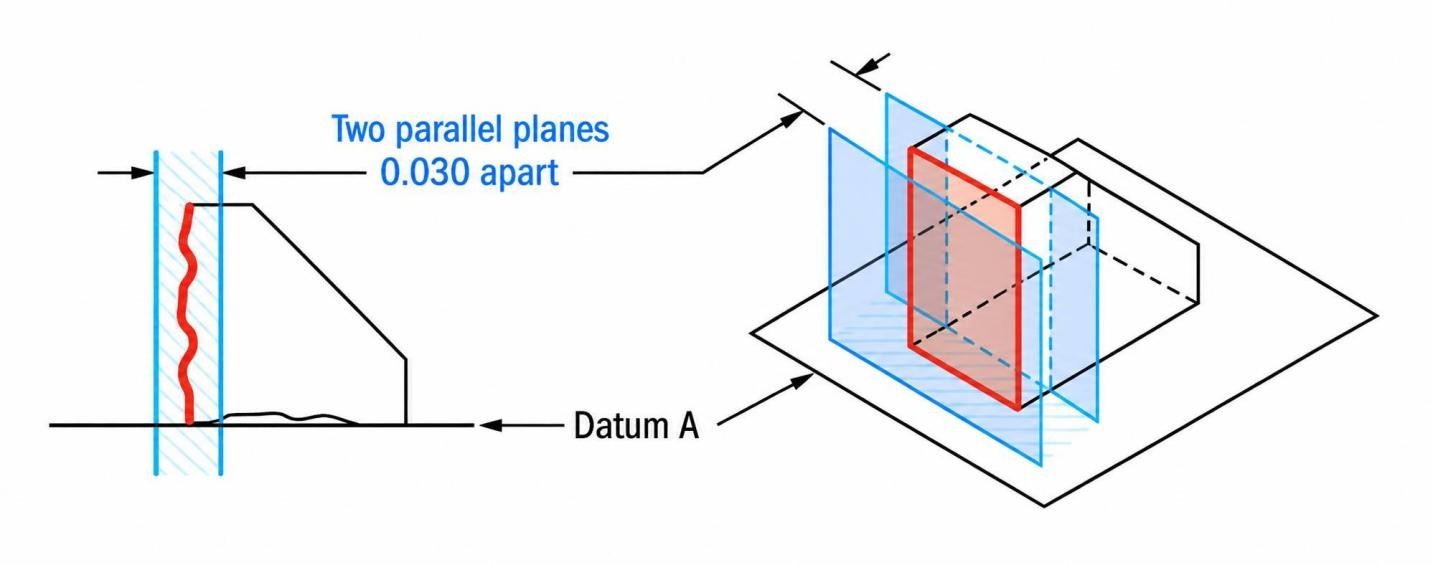
Perpendicularity In GD&T (GD&T Basics)
GD&T perpendicularity is an orientation control that requires a surface, feature axis, or derived center plane to remain oriented at 90° to a referenced datum within the specified tolerance zone.
The examples in this guide follow ASME Y14.5-2018 conventions. Drawings governed by ISO 1101 should be interpreted according to the specified standard, because terminology and interpretation can differ.
The datum provides the reference from which you establish the 90° relationship. Therefore, perpendicularity does not simply mean that two features should look square to each other. You first identify the datum in the feature control frame, then interpret the controlled feature relative to that reference.
You can apply perpendicularity to a surface, a derived axis of a cylindrical feature of size, or a derived median plane of a width feature. The drawing application changes with the feature being controlled, which also affects how you read the requirement.
Perpendicularity Symbol and Datum Reference
Perpendicularity Symbol (Tec-Ease)
The perpendicularity symbol is ⟂. You will find it in the first compartment of the feature control frame, followed by the specified tolerance and the referenced datum.
For example, a feature control frame written as ⟂ | 0.05 | A tells you that perpendicularity is the required geometric control, 0.05 mm is the permitted tolerance, and datum A establishes the reference for the requirement.
You should read the datum reference together with the feature to which the feature control frame applies. If the callout points to a surface, that surface receives the perpendicularity control. If it applies to a feature of size, the requirement controls its derived axis or derived median plane, depending on the feature geometry. Therefore, identifying the controlled feature first prevents you from applying the callout to the wrong geometry.
Surface and Axis Perpendicularity
The controlled geometry depends on how the feature control frame is applied. Surface perpendicularity controls the orientation of the surface relative to the datum, while the resulting tolerance zone also limits the surface's form. The feature control frame attachment therefore determines what must be evaluated during inspection.
Surface Perpendicularity
Surface perpendicularity controls a planar face relative to the referenced datum. When the feature control frame is attached to a surface or its extension line, the perpendicularity requirement applies to that surface.
Take a rectangular machined part with its bottom face identified as datum A. If a perpendicularity callout points to a vertical side face, you apply the requirement to that side face. The control should not be transferred to a part centerline or nearby feature.
Pay particular attention when several faces sit close together on a detailed drawing. Following the callout back to its attachment point helps you identify the exact surface the designer has controlled.
Axis Perpendicularity
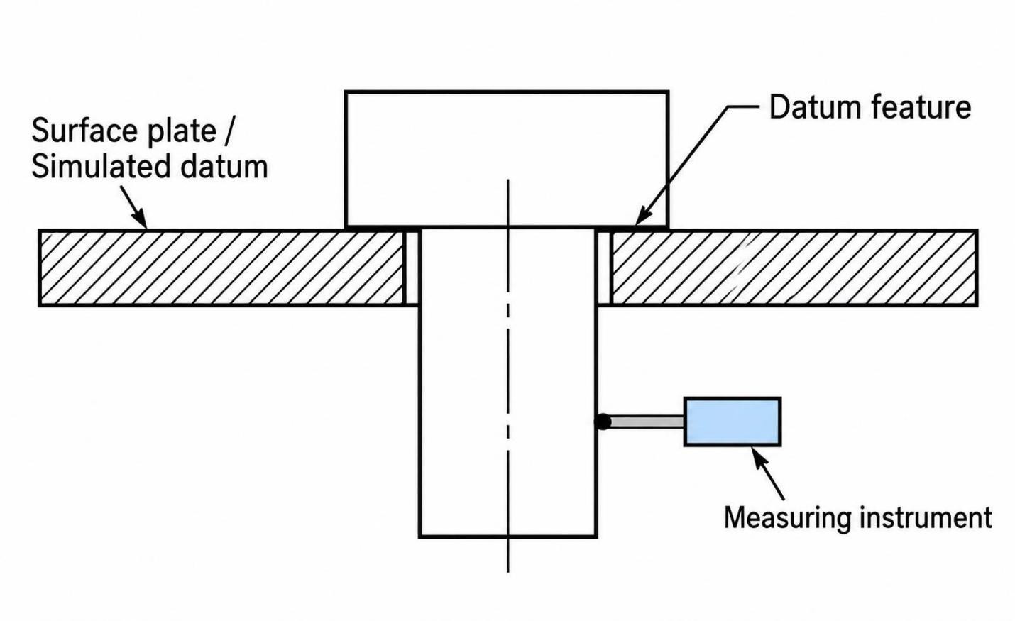
Perpendicularity of an axis (Engineering Essentials)
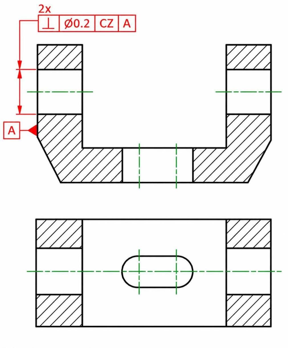
When perpendicularity is applied to a cylindrical feature of size, the requirement controls the feature's derived axis rather than the cylindrical surface itself. Holes, pins, and shafts are common examples. The feature control frame is associated with the feature's size dimension rather than applied directly to its cylindrical surface.
For example, if you see the callout associated with the diameter dimension of a hole, you interpret perpendicularity through the hole's derived axis. This distinction prevents you from treating the callout as surface perpendicularity simply because the hole itself has a cylindrical surface.
A width feature may instead be evaluated through its derived median plane. A slot provides a straightforward example. In that case, you read the perpendicularity requirement against the derived median plane instead of looking for a cylindrical axis.
How the Perpendicularity Tolerance Zone Works
A perpendicularity tolerance does not give you an allowable angle such as 90° ±0.5°. Instead, the datum establishes the reference, and the tolerance value defines a zone oriented exactly 90° to that reference.
The geometry of that zone depends on what you control. For a planar surface, you work with two parallel boundary planes. For a derived axis, the diameter symbol can establish a cylindrical zone.
Surface Tolerance Zone
Geometrical Tolerance (MDPI)
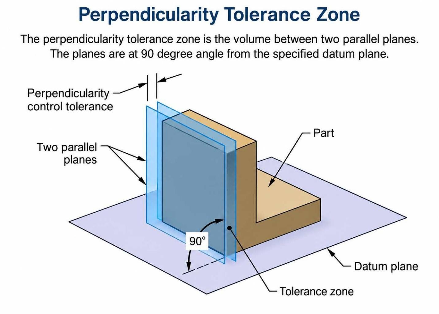
For surface perpendicularity, two parallel planes form the tolerance zone. The planes are separated by the value stated in the feature control frame and oriented exactly 90° to the referenced datum.
Suppose the drawing specifies ⟂ | 0.05 | A on a planar face. Datum A establishes the reference. Two planes positioned perpendicular to datum A then define a 0.05 mm-wide zone. Every point of the controlled surface must fall between those boundaries.
The 0.05 mm value is the separation between the two tolerance-zone boundaries; it is not a maximum 0.05 mm offset from datum A. The two-plane tolerance zone is oriented 90° to the datum, and its location is established to contain the entire actual surface.
Axis Tolerance Zone
An axis perpendicularity callout commonly uses the diameter symbol before the tolerance value. In that case, the tolerance boundary becomes a cylinder whose centerline is oriented exactly 90° to the referenced datum.
For a callout of ⟂ | ⌀0.05 | A, the ⌀0.05 specifies a cylindrical zone 0.05 mm in diameter. The derived axis of the controlled feature must remain within the cylindrical tolerance zone throughout the extent of the feature being controlled.
The ⌀ symbol changes how you interpret the numerical value. Here, 0.05 mm represents the diameter of the tolerance zone rather than the spacing between two parallel planes.
Why Perpendicularity Uses a Linear Tolerance
GD&T establishes the required orientation through a basic 90° relationship to the datum. The perpendicularity value then limits how far the controlled geometry may depart from that theoretically exact orientation within its defined zone.
For a known feature length, an equivalent angular deviation can be estimated from the relationship $d = L \times \tan(\theta)$. This is useful for understanding the relationship between feature length and allowable orientation error, but the drawing requirement is evaluated from the stated GD&T tolerance zone.
The same angular deviation produces a different linear displacement as L changes. For example, 0.05 mm of displacement across 20 mm represents a different angle from 0.05 mm across 100 mm.
A perpendicularity callout therefore specifies the allowable geometric variation as a linear tolerance, expressed in the drawing units. You evaluate whether the controlled surface, axis, or derived median plane remains within its specified tolerance zone.
How to Read a Perpendicularity Callout
When you read a perpendicularity feature control frame, start with the geometric characteristic symbol, then move through the tolerance compartment and datum reference. For a feature of size, you may also see a diameter symbol plus a material condition modifier.
Compare these two representative callouts:
Surface: ⟂ | 0.05 | A
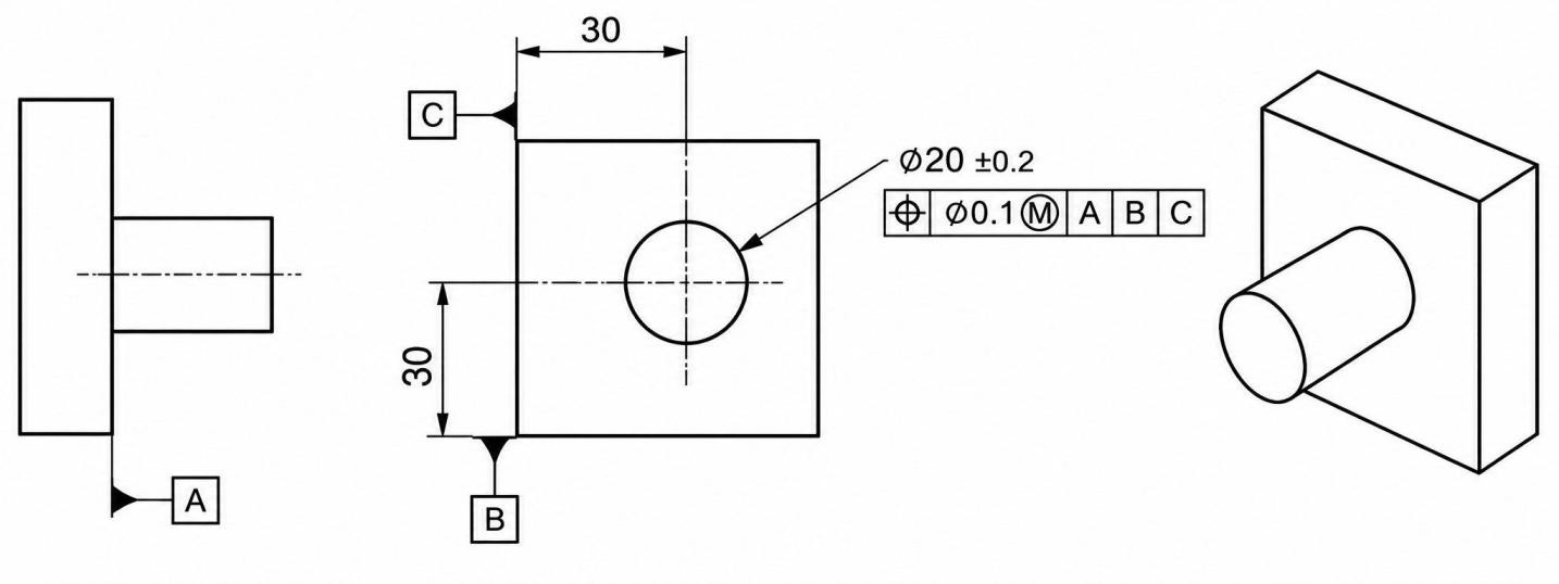
Hole axis: ⟂ | ⌀0.05 Ⓜ | A
The first callout gives you a 0.05 mm perpendicularity tolerance relative to datum A for the indicated surface. No diameter symbol appears because the stated value is not defining a cylindrical zone.
The second callout applies differently. The ⌀ preceding 0.05 tells you the tolerance value defines a cylindrical zone. The Ⓜ following 0.05 specifies that the stated perpendicularity tolerance applies at maximum material condition (MMC). Datum A remains the reference used to establish the required orientation.
For example, consider a hole specified as:
⟂ | ⌀0.10 Ⓜ | A
When the hole is at MMC size, its available perpendicularity tolerance is the stated ⌀0.10 mm. As the actual mating size departs from MMC, additional geometric tolerance becomes available. The amount of this bonus tolerance equals the feature's departure from MMC.
If the same axis callout contains no material condition modifier, the perpendicularity tolerance applies Regardless of Feature Size (RFS) under ASME Y14.5 conventions. You then use the stated geometric tolerance without adding bonus tolerance from the feature's departure from MMC.
Reading the frame in sequence prevents different requirements from being combined. The tolerance value gives the permitted geometric variation, ⌀ identifies a diametrical tolerance value, Ⓜ establishes the applicable material condition, and A identifies the datum reference for the callout.
For CNC parts with perpendicularity requirements, the drawing should be reviewed together with the datum structure, feature geometry, and inspection requirements before machining begins.

Precision CNC Machining Service
Upload your CAD files to get an instant CNC machining quote and DFM feedback from JLCCNC engineers.
Perpendicularity Examples in Engineering Drawings
On a drawing, you rarely read a perpendicularity frame by itself. You check where the frame is attached, identify the datum, then look at the size limits if the controlled feature is a hole or shaft. These three examples show how that reading changes with the feature.
Surface Perpendicularity Example
Perpendicularity of a surface (Engineering Essentials)
A drawing identifies the bottom face of a machined bracket as datum A. An adjacent vertical face carries:
⟂ | 0.05 | A
Here, the 0.05 mm requirement belongs to the indicated vertical face. Datum A is the reference.
You would not use this callout to judge the height of the bracket. You would also keep it separate from any dimensional tolerance controlling the distance between faces. The frame only gives you the perpendicularity requirement assigned to that face.
Hole Axis Perpendicularity Example
Axis Perpendicularity (Mechademic)
Suppose a plate drawing shows a ⌀10 mm hole with:
⟂ | ⌀0.08 | A
Datum A is the plate face. Since the frame applies to the hole as a feature of size, you read the ⌀0.08 mm requirement against its derived axis.
Check the hole size separately. A measured diameter tells you whether the hole meets its size limits; it does not tell you whether its axis meets the perpendicularity callout. Both requirements need their own drawing check.
Perpendicularity with MMC and Bonus Tolerance
GD&T Bonus Tolerance (Mechademic)
Now take a hole with these size limits:
⌀10.0–10.2 mm
The drawing specifies:
⟂ | ⌀0.10 Ⓜ | A
The hole is an internal feature, so its MMC size is 10.0 mm. At exactly 10.0 mm, you have the stated ⌀0.10 mm perpendicularity tolerance.
Now use the measured hole size. If inspection gives 10.12 mm, the hole has departed from MMC by 0.12 mm.
Bonus tolerance = 10.12 − 10.00 = 0.12 mm
Add that departure to the stated geometric tolerance:
Total perpendicularity tolerance = 0.10 + 0.12 = ⌀0.22 mm
The ⌀0.22 mm is the total available geometric tolerance at the measured size, not a new size tolerance for the hole. This is the available perpendicularity tolerance for the MMC-controlled axis. The hole's size requirement still has to be satisfied separately.
That calculation depends on the measured feature size. A 10.05 mm hole would provide 0.05 mm bonus tolerance, whereas a 10.18 mm hole would provide 0.18 mm. You therefore need the drawing size limits plus the actual measured size before calculating the available perpendicularity tolerance at MMC.
How Is Perpendicularity Measured?
Start the inspection from the datum shown in the feature control frame. Your measuring setup must reproduce that reference before the controlled feature can be evaluated. From there, the method depends on whether you are checking an actual surface plus a derived axis.
Measuring Surface Perpendicularity
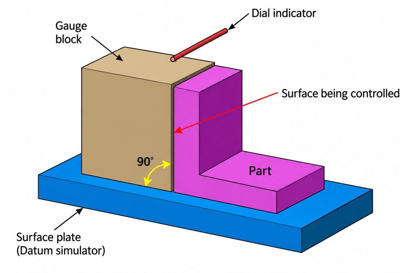
A surface plate and dial indicator provide a practical setup for an accessible perpendicular surface. Seat the datum face against its simulator, then run the indicator over the controlled face.
Do not rely on one indicator reading at the top and another at the bottom. Sweep the face at several positions so your readings represent more of the specified surface. Record the indicator variation while maintaining the datum setup throughout the check.
Part geometry can make this setup difficult. A recessed face, short land, interrupted surface, plus limited indicator access may prevent a useful sweep. In those cases, you need a measurement method capable of reaching enough points on the specified face.
Measuring Axis Perpendicularity
A hole's axis is a derived feature established from the actual surface of the feature of size, so the inspection method must evaluate the axis rather than the cylindrical surface itself.
One practical method uses a suitable inspection mandrel or qualified pin to represent the bore axis. With the part referenced from its specified datum, indicator readings along the exposed mandrel can be used as an indirect check of the hole's axis orientation.
Mandrel fit matters because clearance between the bore and mandrel can introduce movement that affects the reading. The result therefore depends on the mandrel's condition, fit, and the stability of the datum setup.
CMM and Functional Gauging
A CMM lets you measure the datum feature and controlled feature within the same coordinate setup. For a face, probe points across the specified surface. For a bore, collect points at several sections through its depth so the software can derive the feature axis.
The measurement programme should follow the drawing datum structure. Creating a convenient machine alignment that differs from the specified datum reference can change the basis of the evaluation.
Functional gauging is useful for applicable features controlled at MMC. Instead of reporting a numerical perpendicularity result, the gauge checks whether the feature stays within the functional boundary established by its size and geometric requirement.
For an MMC-controlled hole, a fixed pin can represent the hole's virtual-condition boundary while the gauge fixture establishes the required datum relationship. Successful assembly with the gauge provides a conformity check. If you need the actual measured perpendicularity value rather than a pass/fail result, use a quantitative inspection method such as a CMM.
For an internal feature, the virtual-condition boundary is established from the MMC size and the applicable geometric tolerance, so the functional gauge tests the combined assembly boundary rather than perpendicularity in isolation.
Perpendicularity vs Other GD&T Controls
Several drawing controls can describe the direction plus shape of a feature, but they do not place the same requirement on it. The quickest way to separate them is to check three things: whether a datum is required, whether the requirement sets orientation, and whether the drawing controls a surface plus a derived feature.
A direct angular dimension, for example, can specify 90° between two drawing elements. Perpendicularity goes further by placing a geometric limit on the controlled feature relative to its datum. Parallelism also references a datum, but its required direction is parallel rather than 90°.
Flatness differs from all three orientation controls. You use it to limit the form of one surface without referencing another feature as a datum.
Perpendicularity vs Angular Dimension vs Parallelism vs Flatness vs Angularity
| Control | Datum Required? | Orientation Requirement | What You Control | Typical Drawing Use |
|---|---|---|---|---|
| Perpendicularity | Yes | 90° to the referenced datum | Surface, derived axis, plus derived median plane | A face, hole axis, shaft axis, plus center plane specified perpendicular to a datum |
| Angular dimension | Not inherently | Specifies an angle numerically | Angular relationship between identified drawing elements | Defining nominal angular geometry such as 30°, 45°, plus 90° |
| Parallelism | Yes | Parallel to the referenced datum | Surface, derived axis, plus derived median plane | Keeping a face plus feature axis parallel to an established datum |
| Flatness | No | No datum-based orientation | Surface | Limiting form independently from another datum feature |
| Angularity | Yes | A specified basic angle to the datum, typically other than 0° or 90° | Surface, derived axis, plus derived median plane | Controlling an inclined face plus axis at a specified basic angle |
Perpendicularity is the dedicated orientation control for a 90° relationship. Parallelism addresses a parallel relationship, while angularity is used for other specified basic angles. For a fuller comparison of angularity and perpendicularity, see the angularity GD&T guide.
The relationship between parallelism and perpendicularity is straightforward: both are orientation controls referenced to a datum, but parallelism requires a parallel orientation while perpendicularity requires 90°.
Flatness answers a different drawing question. A surface may satisfy its flatness requirement yet still sit at an unacceptable orientation relative to another feature because flatness has no datum reference. Likewise, adding a 90° angular dimension alone does not create a GD&T perpendicularity requirement.
Select perpendicularity based on the functional relationship that must be controlled, not simply because a feature appears visually square. The datum, controlled geometry, and required location relationship determine whether perpendicularity, position, parallelism, flatness, or another control is appropriate.
Perpendicularity in CNC Machining
In CNC machining, perpendicularity is established through the combined relationship between the machined datum, part location, setup alignment, and the process used to generate the controlled feature. When a feature is produced in a different setup from its datum, setup transfer becomes a major source of perpendicularity error. If a base face is datum A, the machining sequence and workholding should preserve that datum relationship when producing any face, bore, shoulder, or slot controlled from A.
The difficult cases usually appear when the datum and controlled feature cannot be finished from one orientation. The resulting accuracy then depends on fixture location, setup transfer, and the geometry established in earlier operations.
Common CNC Applications
A typical milling case is a vertical wall controlled from a machined base. If both surfaces can be finished while the part remains located in one setup, the machine axes establish much of their geometric relationship. A second setup changes the situation because the finished base may become the locating surface for the next operation.
Shoulders on turned parts create another useful case. The spindle establishes the rotational axis, while facing generates the shoulder. Perpendicularity can be specified where the drawing requires the shoulder to maintain its 90° relationship to a datum axis.
Bores require different process thinking. Drilling establishes the initial bore path, while boring or other corrective operations may be used when tighter control of the final axis is required. Reaming primarily improves hole size and surface condition and should not be treated as a general solution for correcting a significantly misdirected hole. For a long bore, controlling the entrance alone says little about what happens farther through the feature. Tool guidance and cutting behaviour through the full depth become relevant to the finished axis.
Manufacturing Factors That Affect Perpendicularity
Look first at how the controlled geometry is generated. When an end mill finishes a tall wall, cutter deflection can change along the axial engagement. The lower part of the wall may therefore be generated under a different cutting condition from the upper part. Reducing tool overhang, using a more stable finishing strategy, and increasing cutter diameter where geometry permits can reduce wall deflection and improve perpendicularity.
A bore has another set of influences. Drill walk at entry can shift the path before the tool reaches full engagement. Long boring bars can deflect under radial cutting force. Reaming follows an existing hole closely, so it should not be treated as a general correction for a poorly directed bore.
Setup transfer deserves attention when the datum was machined earlier. If datum A is the finished base face, locating a later operation from raw stock instead of that finished datum can introduce a setup relationship that no longer matches the drawing's datum structure. Fixture design should give the specified datum a usable locating role where the machining sequence permits it.
Part geometry can restrict that plan. A datum may be easy to identify on the drawing but difficult to seat against a fixture because bosses, interrupted areas, and surrounding features block contact. Similarly, a deep pocket may force a long cutter even though a shorter tool would produce the wall more consistently.
Specifying Perpendicularity for CNC-Machined Parts
Before placing a perpendicularity callout, look at the feature length as well as the numerical tolerance. The same 0.03 mm perpendicularity tolerance becomes progressively more demanding as the controlled feature gets longer because the allowable angular deviation becomes smaller over that length.
Datum accessibility also deserves a drawing review. If production cannot physically locate from the selected datum while machining the controlled feature, the process may require an intermediate fixture, transferred reference, plus additional setup.
For holes, review diameter and depth together with the perpendicularity requirement. A short, large-diameter bore gives the machinist different tooling options from a small-diameter hole with a high depth-to-diameter ratio. The drawing value should come from the allowable feature relationship, while the geometry tells you how difficult that requirement will be to produce.
You can also avoid unnecessary control by separating functional features from nominally square geometry. A perpendicularity callout belongs on the feature whose 90° relationship has a defined requirement. Other faces can remain under the applicable drawing tolerances instead of receiving the same geometric value by default.
Perpendicularity FAQs
Does perpendicularity require a datum?
A perpendicularity callout uses a datum to establish its reference orientation. The controlled feature is then related to that datum at the required 90° orientation.
Can perpendicularity be applied to a hole?
For a hole, perpendicularity can control the derived axis. You will typically see the feature control frame associated with the hole dimension when the requirement applies to its axis.
Does perpendicularity directly control a 90-degree angle?
Perpendicularity does not state an allowable angular variation such as 90° ±0.5°. The 90° relationship comes from the datum reference, while the perpendicularity tolerance is given as a linear value.
What does perpendicularity control?
Perpendicularity controls the orientation of a surface, feature axis, or derived center plane relative to a datum. It controls orientation, not feature location by itself.
Can perpendicularity use MMC?
MMC can accompany a perpendicularity tolerance applied to an eligible feature of size. As the actual feature size departs from MMC, the available perpendicularity tolerance can increase by the corresponding bonus tolerance.
Does perpendicularity control flatness?
A surface perpendicularity tolerance also limits the form of the controlled surface because the entire surface must fit within the two-plane tolerance zone. A separate flatness tolerance is only needed when an independent form requirement must be specified without reference to a datum.
Under ASME Y14.5-2018, surface perpendicularity also controls the form of the surface within the orientation tolerance zone. When the design intent is to control the orientation of the surface's tangent plane without using the perpendicularity tolerance to limit surface flatness, the tangent plane modifier may be specified.
What is the difference between perpendicularity and position?
Perpendicularity controls orientation relative to a datum, while position controls the location of a feature relative to basic dimensions and its datum reference frame. A position tolerance applied to a feature of size can also constrain its orientation.
Precision CNC Machining Service
Professional manufacturing, fast turnaround, and quality assurance.
Conclusion About Perpendicularity
Perpendicularity gives you a controlled way to define a 90° relationship from a datum. Correct use starts with identifying the feature being controlled, reading the feature control frame correctly, and assigning a tolerance that reflects the part's functional requirements.
For CNC parts, the drawing should also account for how the datum and controlled feature can be established during production. Feature depth, access, setup changes, workholding, and tool reach can influence the machining approach required to meet the specified value.
If your design includes perpendicular faces, bores, shoulders, or other datum-related features, JLCCNC can manufacture custom CNC parts from your engineering drawings and GD&T requirements. Send your CAD files and technical drawings to JLCCNC for a machining review and project quote.
Keep Learning
GD&T Datum: Definition, Types, Symbols, and Datum Reference Frame
Key Takeaways A datum in GD&T is a theoretically exact reference used to locate or orient other features on a part. It is not the physical surface itself. A datum feature is the physical feature identified on the part and used to establish a datum. The datum itself is the theoretically exact geometric reference derived from that feature. Datums become especially important when several features have to work together. A hole pattern, bearing bore, mounting face, or mating surface may need to establish t......
GD&T Runout: Definition, Symbol, Measurement & Tolerance
Key Takeaways Runout limits surface variation while a part rotates around its specified datum axis. The datum feature establishes the axis used for the runout requirement. You compare the full indicator variation during rotation with the tolerance stated on the drawing. Circular runout applies at individual circular sections of the controlled surface. Total runout evaluates the controlled surface across its specified extent. Runout is not a size tolerance, and its value is not determined by the diamet......
GD&T Perpendicularity: Definition, Tolerance & Examples
Key Takeaways Perpendicularity is an orientation control used for a feature specified at 90° to a datum. A surface callout controls the complete surface within two parallel planes set perpendicular to the referenced datum. An axis callout controls the derived axis inside the specified tolerance zone instead of controlling the physical surface directly. Perpendicularity does not establish the location of a feature. A drawing can require another geometric control when position also needs definition. Dat......
Concentricity in GD&T: Definition, Symbol, Tolerance, and Measurement
Key Takeaways Concentricity in legacy ASME GD&T controls the derived median points of a feature relative to a datum axis. It does not simply compare the axes of two fitted cylinders. Check the drawing standard first. Legacy ASME concentricity and ISO concentricity or coaxiality should not be interpreted as equivalent requirements. For the cylindrical example in this guide, the tolerance zone is a cylinder centered on the datum axis. The derived median points of the controlled feature must lie within t......
Engineering Fits: Clearance, Transition, and Interference Fits
Key Takeaways Engineering fits describe the dimensional relationship between two mating parts, specifically whether assembly produces clearance (gap), interference (overlap), or a result that could be either. Clearance fit always produces a gap; the shaft is always smaller than the hole. Interference fit always produces overlap; the shaft is always larger than the hole and force or temperature is needed to assemble. Transition fit can produce either a small clearance or small interference depending on......
What Is Design for X (DFX)? Principles, Types & Applications
Key Takeaways A part can work exactly as intended and still create problems in manufacturing, assembly, inspection, service, or cost. DFX brings these downstream considerations into the design stage, while design changes are still relatively easy to make. DFX principles don't replace functional requirements. They identify where those requirements create downstream problems and find ways to resolve the conflict before tooling, production, or launch. DFX is not a single method. It's a collection of over......