GD&T Runout: Definition, Symbol, Measurement & Tolerance
21 min
- What Is GD&T Runout
- GD&T Runout Symbol and Drawing Callout
- Circular Runout vs Total Runout
- How to Measure Runout
- Runout vs Other GD&T Controls
- Where GD&T Runout Is Used in CNC Machining
- GD&T Runout FAQs
- Conclusion About GD&T Runout
Key Takeaways
- Runout limits surface variation while a part rotates around its specified datum axis.
- The datum feature establishes the axis used for the runout requirement.
- You compare the full indicator variation during rotation with the tolerance stated on the drawing.
- Circular runout applies at individual circular sections of the controlled surface.
- Total runout evaluates the controlled surface across its specified extent.
- Runout is not a size tolerance, and its value is not determined by the diameter dimension. However, size and runout tolerances can interact: both may constrain the resulting form of a feature, so a feature can meet its size limits and still fail its runout requirement.
- This article follows the GD&T conventions of ASME Y14.5-2018 (R2024). ISO 1101:2017 is a separate GPS standard for geometrical tolerancing, so drawing requirements should always be interpreted according to the governing standard specified for the project.
What Is GD&T Runout
Runout In GD&T (Machining Doctor)
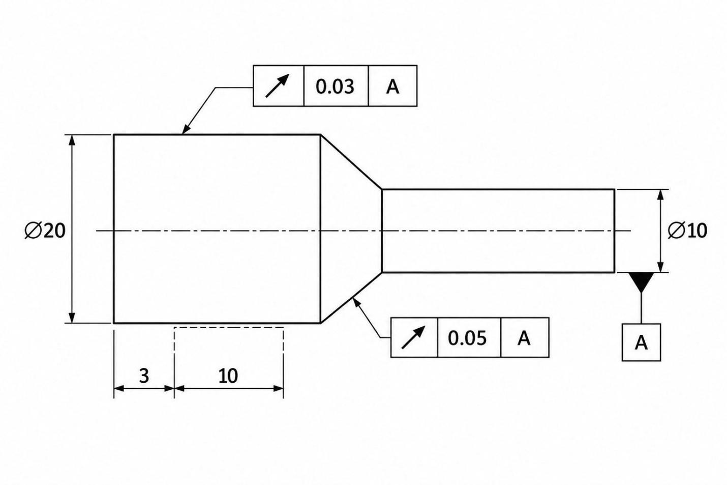
GD&T runout is a geometric control that limits how a surface varies relative to a datum axis. In inspection, the controlled surface is commonly evaluated while the part rotates about that datum axis. Circular runout controls individual circular elements, while total runout controls the surface simultaneously across its specified extent.
Interpret the requirement from the feature control frame, datum reference, and controlled surface together. First, a datum feature establishes the reference axis. The controlled surface is related to that axis, not simply to its own centre. As the part rotates about the datum axis, each point on the applicable circular element follows the rotational relationship defined by the drawing.
The tolerance value sets the maximum permitted variation of the controlled surface during that rotation. A callout of 0.03 mm runout to datum A, for example, permits no more than 0.03 mm of runout variation for the surface under the stated control. The value does not represent the surface diameter, radial distance from datum A, or a ±0.03 mm dimensional limit.
Runout Tolerance Zone
Tool Runout Tolerance (eMachineshop)
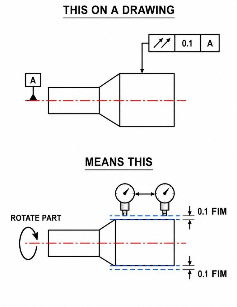
For circular runout on a cylindrical surface, the tolerance applies independently at each circular element taken perpendicular to the datum axis. At a given section, the surface must remain between two coaxial circles separated radially by the specified runout tolerance. Their common centre lies on the datum axis.
The two circular boundaries may vary in diameter within the applicable size limits. The runout value defines the radial separation between them, not a ± dimensional tolerance about a nominal diameter.
A 0.02 mm circular runout requirement therefore allows a radial separation of 0.02 mm between those boundaries at each evaluated circular element. You do not divide the stated value into ±0.01 mm about a nominal surface.
The zone follows the geometry of the controlled surface. On a planar face perpendicular to the datum axis, each circular element has its own tolerance zone bounded by two equal-diameter circles centered on the datum axis. The two circles lie in parallel planes normal to the datum axis, with an axial separation equal to the specified tolerance. Conical surfaces use circular elements taken at the applicable section of the controlled surface.
Total runout uses a different zone because the requirement applies across the full controlled surface rather than independently at individual circular elements. That distinction is covered separately when circular runout and total runout are discussed.
GD&T Runout Symbol and Drawing Callout

GD&T Runout Symbol (Tech - Ease)
To read a GD&T runout callout, identify the runout symbol first, then read the tolerance value and datum reference, and finally follow the feature control frame leader to the controlled surface.
A runout requirement appears in a feature control frame attached to the surface under control. In a basic runout feature control frame, the key information is the runout type, specified tolerance, and datum reference. More complex callouts may include additional datum references or applicable modifiers.
For example, a circular runout callout may appear as:
↗ | 0.03 | A
Here, ↗ represents circular runout, 0.03 mm is the allowed runout, and A identifies the datum used to establish the rotational axis. The leader from the feature control frame shows which surface carries the requirement.
Runout is specified without MMC or LMC modifiers. The stated runout tolerance does not increase with the actual size of a feature of size, so no bonus runout tolerance is added based on departure from MMC.
Runout does not always apply to the full nominal surface. When only a portion of a cylindrical or planar surface is controlled, the drawing can define the controlled extent with basic dimensions and the appropriate line convention or with the “between” symbol. The inspection should follow the specified axial or radial limits rather than assuming that the entire feature is subject to the runout requirement.
Runout Symbol and Feature Control Frame
GD&T uses separate symbols for circular runout and total runout. Circular runout uses a single arrow symbol, while total runout uses a double-arrow symbol. Checking the symbol first tells you which runout requirement the drawing specifies.
The tolerance value occupies the next compartment. If the frame shows 0.03, the controlled surface has a 0.03 mm runout limit, assuming the drawing uses millimetres. Runout does not use a diameter symbol before this value because the number states the permitted runout rather than a cylindrical zone diameter.
Follow the feature control frame leader to see which surface receives the callout. On a stepped shaft drawing, for example, the leader may terminate at one specific outside diameter. The requirement belongs to that indicated surface rather than every cylindrical feature shown on the part.
Datum Reference and Drawing Interpretation
Datum References
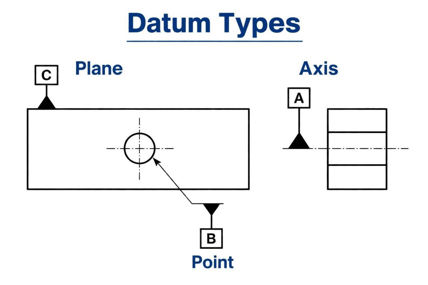
Under ASME Y14.5, the datum reference in a runout feature control frame identifies the datum feature or datum features used to establish the datum axis. For runout applications, the datum is typically specified at RMB, and the axis may be established by one sufficiently long cylindrical datum feature, two or more separated cylindrical datum features, or a cylindrical feature combined with a perpendicular face. If the frame ends with A, you need to find the datum feature symbol A elsewhere on the drawing and see which feature establishes that datum.
The datum scheme should reflect how the part is functionally located and rotated in the assembly. The controlled surface is then evaluated in relation to that axis. You should not assume that the axis of the controlled diameter itself becomes the rotational reference.
The attachment of the callout is therefore just as useful as the numbers inside it. One part may contain several turned diameters, yet the runout frame can apply to only one of them. Reading the leader and datum reference together tells you which surface is controlled and which feature provides its rotational reference.
Have a CNC part with a runout requirement? Upload your CAD model and drawing to JLCCNC for a DFM review of the datum, controlled surface, and tolerance before quoting.

Precision CNC Machining Service
Professional manufacturing, fast turnaround, and quality assurance.
Circular Runout vs Total Runout
Circular vs total runout (www.dimcax.com)
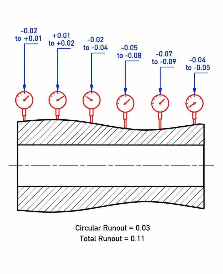
The practical difference between circular runout and total runout appears along the length of the controlled surface. Circular runout allows each cross-section to satisfy the stated value independently. Total runout does not separate the surface into independent sections; the specified value applies while the indicator covers the full controlled surface.
Because of that difference, two parts can meet the same circular runout limit at the inspected sections while having different surface relationships along the length between those sections. Total runout addresses that axial change as part of the requirement.
Circular Runout
Consider a cylindrical journal checked near its left end, centre, and right end. With circular runout, you keep the indicator at one axial location while the journal completes a revolution. You then move to the next location and make another independent check.
Suppose the drawing specifies 0.02 mm circular runout. If the indicator varies by 0.015 mm at one section and 0.018 mm at another, both sections satisfy a 0.02 mm circular runout requirement. Each circular element only has to remain within the 0.02 mm limit assigned to it.
The important point is what happens between those sections. Each axial section is evaluated independently, so a compliant section does not compensate for or combine with a different section. A gradual change in the journal surface along its length is therefore not evaluated as one total variation under circular runout.
Total Runout
For a cylindrical surface, total runout creates a tolerance zone bounded by two coaxial cylinders with a radial separation equal to the specified tolerance. For a planar surface perpendicular to the datum axis, the zone is bounded by two parallel planes separated by the specified tolerance. Unlike circular runout, the zone applies to all surface elements simultaneously.
Now apply 0.02 mm total runout to the same journal. The indicator is no longer kept at one axial section for the complete evaluation. It traverses the controlled length while the journal rotates.
All readings collected across that surface must remain within the same 0.02 mm total range. A section near one end cannot use one 0.02 mm range while another section effectively uses a shifted range elsewhere on the surface.
That difference exposes geometry that isolated circular checks may not show. For example, a journal can have acceptable circular sections while its surface gradually changes relative to the datum axis along the journal length. Total runout includes that change in the final result.
When to Use Circular Runout or Total Runout
Start with the surface area that the drawing actually needs to constrain. If the requirement concerns how individual circumferences run about the datum axis, circular runout gives you that control without tying every axial location into one measured range. A short locating diameter can be a suitable case when controlling each circular element satisfies the design requirement.
Use total runout when variation from one end of the controlled surface to the other also needs to stay inside the stated value. A long journal working across its full length is a clearer example because changes along that length can affect the surface relationship even when individual sections show low circular runout.
The same reasoning applies to a face. Circular runout checks individual circular paths at selected radii. Total runout covers the face across the specified radial extent. If variation from the inner radius toward the outer radius needs to remain under one requirement, total runout addresses that condition directly.
| What You Need From the Drawing | Circular Runout | Total Runout |
|---|---|---|
| Check one circumference at a time | Applies | Not evaluated independently |
| Evaluate the entire controlled surface within one tolerance zone | No | Yes |
| Limit change along a cylindrical surface | Not as one combined requirement | Yes |
| Check a face at separate radii | Applies to each circular path | Full radial extent is considered |
| One tolerance range across the controlled surface | No | Yes |
| Indicator movement during evaluation | Held at one section for each revolution | Traversed across the surface during rotation |
| Useful selection question | Do individual circular sections need control? | Must the full surface remain within one runout range? |
How to Measure Runout
Runout inspection should reproduce the datum relationship stated on the drawing. Before placing an indicator on the controlled surface, the inspector establishes the datum axis from the specified datum feature. The part then remains referenced to that axis throughout the check.
A dial indicator, test indicator, bench centre arrangement, precision spindle, suitable mandrel, plus a dedicated runout fixture can support the inspection. Fixture selection depends on the datum feature and part geometry. The fixture itself does not define the inspection axis; the drawing datum does.
Establishing the Datum Axis
Start by locating the datum feature identified in the runout feature control frame. For a shaft with centre holes defining the intended datum setup, the part can be supported between suitable centres. An internal cylindrical datum may instead require a close-fitting mandrel. Other datum features can require a spindle fixture designed around their specified datum relationship.
Clean the datum contact surfaces before mounting the part. A chip beneath a centre contact, a burr on a locating diameter, a damaged datum surface, a loose mandrel fit, or fixture movement can shift the rotational axis during inspection. The indicator then includes setup error in the runout reading.
Do not centre the controlled surface first and then inspect that same surface. Do not use the controlled surface itself to establish the rotation axis unless the drawing explicitly defines it as the datum feature. Otherwise, the setup can effectively reference the feature to its own axis and hide the very positional or coaxial variation that the runout callout is intended to control. Establish the datum axis first. The controlled surface must be allowed to show its actual variation relative to that reference.
Measuring Circular Runout
Place the indicator at the circular section being inspected. On a cylindrical surface, position the contact so its measuring direction is radial to the datum axis. Keep the contact point at the same axial position throughout one complete revolution.
Apply enough indicator preload to maintain contact through the full rotation. For cylindrical surfaces, orient the indicator so that its sensing direction is normal to the surface and approximately radial to the datum axis. An incorrect contact angle can introduce cosine error and cause the indicator to report only a component of the actual surface displacement.
Rotate the part slowly through 360°. Watch the indicator through the complete revolution and record its highest and lowest readings. Subtract the minimum reading from the maximum reading. The resulting full indicator movement is the circular runout at that section.
Circular runout applies independently to each applicable circular element of the controlled surface. During inspection, measurements are taken at sufficient locations to verify that the requirement is met throughout the specified surface. Each location produces its own circular-runout result. A low reading near one end cannot be used to offset a higher reading at another section.
For circular runout on a face, place the contact at the required radius and orient the indicator along the datum-axis direction. Keep that radius fixed during the revolution. Moving the contact radially while taking the reading would change the inspection from an individual circular path to a different evaluation.
Measuring Total Runout
Total runout requires the indicator to cover the controlled surface rather than remain at one section. On a cylindrical surface, set the contact radially and begin near one end of the specified length. Rotate the part about the established datum axis while traversing the indicator along the surface.
Track the highest and lowest readings encountered anywhere within the controlled length. Do not reset the indicator after moving to another axial position. The difference between the overall maximum and overall minimum becomes the total-runout result for that surface.
The traverse also needs adequate coverage. Checking only the two ends can miss a high point, low point, barrel-shaped region, taper, or another surface change between them. Indicator movement should therefore cover the specified surface sufficiently to capture its maximum variation.
For total runout on a face, orient the indicator in the axial direction and traverse it across the controlled radial width while the part rotates. Maintain contact through the sweep and retain one maximum-to-minimum reading range for the complete controlled face.
For a conventional indicator-based inspection, full indicator movement (FIM) is calculated as the maximum reading minus the minimum reading. A 0.025 mm runout requirement therefore limits the measured FIM to 0.025 mm or less. Under ASME Y14.5-2018, however, the runout tolerance itself is defined geometrically. FIM is an inspection method used to evaluate the requirement, not the definition of the tolerance zone.
CMM Inspection for Runout
CMM inspection can also evaluate runout by establishing the datum reference from the specified datum feature and evaluating measured surface points or sections against the applicable tolerance zone. For tight runout requirements, the result depends on datum simulation, probe access, surface sampling strategy, and the evaluation method used by the inspection software. A CMM result should therefore be interpreted from the drawing requirement rather than treated as a direct replacement for a dial-indicator FIM reading.
Runout vs Other GD&T Controls
Before adding runout to a drawing, check whether the requirement actually depends on another axis. A turned diameter may need good roundness by itself, good form over its complete length, or controlled rotation relative to a bearing bore, journal, pilot, or another datum feature. These are different drawing requirements.
Use runout when the functional requirement is tied to how a surface rotates relative to an axis established by another datum feature. Circularity and cylindricity are form controls, so they do not establish a relationship with another feature. Concentricity references a datum, although it evaluates derived median points rather than the direct movement of the surface.
Circular Runout vs Circularity
Take a shaft diameter that will run inside a bearing. If the drawing only specifies circularity, inspection asks whether each measured cross-section has acceptable round form. The bearing diameter can satisfy that requirement even when its centre does not coincide with the axis of an adjacent locating journal.
If the locating journal establishes the assembly axis, circular runout addresses the missing relationship. Its datum reference ties the bearing surface to that journal axis.
So, checking circularity cannot replace a circular runout inspection. The first checks the cross-sectional form; the second includes where that surface runs relative to the specified datum axis.
The JLCCNC circularity guide covers circularity separately.
Total Runout vs Cylindricity
A similar issue appears with long cylindrical fits. Consider a sleeve whose internal bore locates the part while its outside diameter runs inside another component. Checking cylindricity of the outside diameter tells you whether its cylindrical form stays within the specified form tolerance. The bore does not take part in that evaluation.
If the outside diameter must run about the bore axis, the drawing needs a datum-based control. Total runout can reference the bore and control the outside surface across its length relative to that axis.
An inspector therefore should not accept a cylindricity report as evidence of total runout compliance. The cylindricity data may show an excellent cylindrical surface while saying nothing about its relationship with the datum bore.
For the form-only requirement, see the JLCCNC Cylindricity Guide.
Runout vs Concentricity
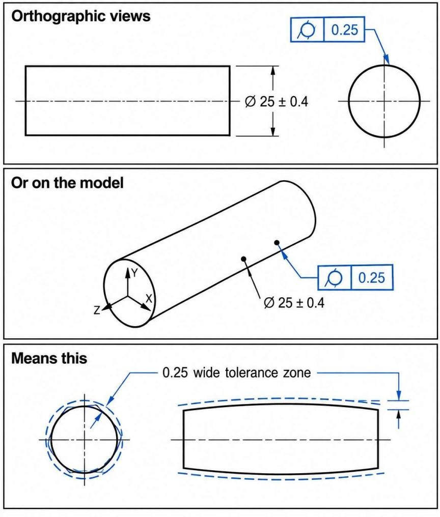
GD&T Cylindricity (Engineering Edge)
Concentricity needs more care because both callouts can reference a datum axis. The difference lies in what the inspection result represents.
With runout, the actual surface provides the indicator movement as the part rotates about the datum axis. Concentricity does not use that surface movement as its acceptance value. Its evaluation is based on derived median points obtained from opposed surface measurements.
Therefore, a dial indicator showing 0.01 mm runout does not establish a 0.01 mm concentricity result. They are different measured quantities despite both being associated with an axis.
If an existing drawing specifies concentricity, follow the requirement shown rather than replacing it with a runout check at inspection. The JLCCNC concentricity guide explains the median-point requirement in detail.
| Control | Datum Reference | Geometry Being Controlled | Inspection Basis |
|---|---|---|---|
| Circular runout | Required | Surface variation at each circular section relative to datum axis | Indicator reading at a fixed section during rotation |
| Total runout | Required | Variation across the complete controlled surface relative to datum axis | Indicator readings collected across the surface during rotation |
| Circularity | None | Roundness of individual cross-sections | Form of each measured circular profile |
| Cylindricity | None | Form of the complete cylindrical surface | Measured points across the cylindrical surface |
| Concentricity | Required | Derived median points relative to datum axis | Median points calculated from opposed surface measurements |
Where GD&T Runout Is Used in CNC Machining
Runout callouts are common on turned and bored parts with several functional surfaces around one rotational centreline. Typical drawing locations include bearing journals, seal tracks, gear seats, hub pilots, precision bores, flange faces, shoulders, and tapered seats.
Shafts, Bearing Journals, and Stepped Diameters
On a shaft drawing, look at what sits next to the bearing journal. A seal may run on a smaller diameter, a gear may fit over another step, and a coupling may mount near the shaft end. These surfaces rotate with the journal, so their runout can be specified from the journal datum.
Seal tracks are a good example. The seal lip stays in contact with the rotating surface, making radial movement of that surface relevant to the contact condition. A runout requirement on the seal track controls it from the shaft datum used on the drawing.
Stepped diameters also appear on shafts carrying gears, pulleys, and couplings. Runout may be applied to the mounting seat when the fitted component must rotate about the datum established by another journal.
Bores, Hubs, and Internal Rotating Features
A hub drawing often uses its finished mounting bore as the datum feature. The runout callout may then appear on the outside pilot, rim, bearing seat, or another diameter machined around that bore.
In a pulley hub, the finished bore may establish the shaft axis while the outside pilot or rim must remain controlled relative to that axis. The bore determines its position on the shaft, while the machined outside features rotate around the bore centreline. Controlling those surfaces from the bore keeps the drawing tied to the feature that actually locates the pulley.
Internal runout requirements appear on parts with more than one functional bore. A housing can have a locating pilot and a bearing bore, for example. If the pilot establishes the component position, the bearing bore can be controlled from that datum rather than treated as an unrelated internal diameter.
Flange Faces, Tapers, and Other Rotating Surfaces
Runout on a flange drawing is often attached to the mating face. The central pilot or bore provides radial location, while the face provides axial seating. The callout connects these two functional surfaces.
Shoulders on shafts use the same type of functional relationship. A bearing inner ring may locate on the journal and seat against the shoulder. Runout on the shoulder addresses the face that the bearing contacts rather than adding another control to the journal itself.
Tapers present another case. A tapered seat may locate a mating component along both its circumference and length. Runout can be applied to the taper when that seating surface must follow a datum established elsewhere on the part.
Apply runout only where the rotational relationship between the controlled surface and the datum axis affects fit, sealing, alignment, contact, balance, or functional motion.
GD&T Runout FAQs
Does GD&T Runout Require a Datum?
Runout always requires a datum. In a typical part-level GD&T runout callout, the datum reference establishes the reference axis used to evaluate the controlled surface. At the assembly level, the axis of rotation may instead be controlled relative to a datum reference frame without itself being a datum axis.
For a shaft, a bearing journal may establish that datum axis. Any runout applied to another diameter is then checked relative to the journal axis, not the centre of the controlled diameter itself.
Can Circular Runout Be Applied to a Flat Surface?
Circular runout can control a flat face perpendicular to the datum axis. A flange face is a typical example.
The indicator contacts the face at a fixed radius while the part makes one full rotation. The difference between the highest and lowest readings at that radius must stay within the specified circular runout tolerance.
Does Runout Control Form as Well as Surface Location?
Runout can limit form error, but it does not simply locate a surface. Any surface error that increases the runout reading counts against the specified tolerance.
Circular runout applies this limit at each circular section. Total runout also includes variation across the controlled surface, such as changes along a cylindrical length.
Is Runout the Same as Concentricity?
No. On legacy ASME drawings, concentricity and runout evaluate different characteristics. Concentricity evaluates derived median points relative to a datum axis, while runout evaluates actual surface variation relative to that axis. Concentricity was removed as a supported control in ASME Y14.5-2018, so legacy callouts should be interpreted according to the standard revision governing the drawing.
Precision CNC Machining Service
Professional manufacturing, fast turnaround, and quality assurance.
Conclusion About GD&T Runout
Runout should come from the way the finished part works. If a journal, bore, face, or taper must run from a specified datum axis, the drawing should state that relationship clearly. The tolerance should also reflect what the assembly actually requires.
Before releasing the drawing, check the datum feature, controlled surface, and runout value together. These three details give the machinist a clear requirement and give inspection a defined basis for acceptance.
For CNC parts, include the applicable datum references, controlled surfaces, and critical dimensions with the quotation request. JLCCNC can review the drawing requirements together with the CAD model before production.
Keep Learning
GD&T Datum: Definition, Types, Symbols, and Datum Reference Frame
Key Takeaways A datum in GD&T is a theoretically exact reference used to locate or orient other features on a part. It is not the physical surface itself. A datum feature is the physical feature identified on the part and used to establish a datum. The datum itself is the theoretically exact geometric reference derived from that feature. Datums become especially important when several features have to work together. A hole pattern, bearing bore, mounting face, or mating surface may need to establish t......
GD&T Runout: Definition, Symbol, Measurement & Tolerance
Key Takeaways Runout limits surface variation while a part rotates around its specified datum axis. The datum feature establishes the axis used for the runout requirement. You compare the full indicator variation during rotation with the tolerance stated on the drawing. Circular runout applies at individual circular sections of the controlled surface. Total runout evaluates the controlled surface across its specified extent. Runout is not a size tolerance, and its value is not determined by the diamet......
GD&T Perpendicularity: Definition, Tolerance & Examples
Key Takeaways Perpendicularity is an orientation control used for a feature specified at 90° to a datum. A surface callout controls the complete surface within two parallel planes set perpendicular to the referenced datum. An axis callout controls the derived axis inside the specified tolerance zone instead of controlling the physical surface directly. Perpendicularity does not establish the location of a feature. A drawing can require another geometric control when position also needs definition. Dat......
Concentricity in GD&T: Definition, Symbol, Tolerance, and Measurement
Key Takeaways Concentricity in legacy ASME GD&T controls the derived median points of a feature relative to a datum axis. It does not simply compare the axes of two fitted cylinders. Check the drawing standard first. Legacy ASME concentricity and ISO concentricity or coaxiality should not be interpreted as equivalent requirements. For the cylindrical example in this guide, the tolerance zone is a cylinder centered on the datum axis. The derived median points of the controlled feature must lie within t......
Engineering Fits: Clearance, Transition, and Interference Fits
Key Takeaways Engineering fits describe the dimensional relationship between two mating parts, specifically whether assembly produces clearance (gap), interference (overlap), or a result that could be either. Clearance fit always produces a gap; the shaft is always smaller than the hole. Interference fit always produces overlap; the shaft is always larger than the hole and force or temperature is needed to assemble. Transition fit can produce either a small clearance or small interference depending on......
What Is Design for X (DFX)? Principles, Types & Applications
Key Takeaways A part can work exactly as intended and still create problems in manufacturing, assembly, inspection, service, or cost. DFX brings these downstream considerations into the design stage, while design changes are still relatively easy to make. DFX principles don't replace functional requirements. They identify where those requirements create downstream problems and find ways to resolve the conflict before tooling, production, or launch. DFX is not a single method. It's a collection of over......