Cylindricity GD&T: Symbol, Tolerance Zone, and Engineering Applications
18 min
- What Is Cylindricity in GD&T?
- Cylindricity Definition in One Sentence
- Cylindricity Symbol
- How Cylindricity GD&T Differs from Circularity, Straightness, and Runout
- When to Specify Cylindricity GD&T
- How Is Cylindricity Measured?
- Cylindricity in CNC Machining
- Common Mistakes When Applying Cylindricity GD&T
- FAQ About Cylindricity GD&T
- Conclusion About Cylindricity GD&T
Key Takeaways
- Cylindricity GD&T is a form control that limits the total deviation of a cylindrical surface, every point on the surface must fall between two coaxial cylinders separated by the tolerance value.
- The cylindricity symbol is two angled lines forming a parallelogram shape in the feature control frame.
- Cylindricity GD&T never requires a datum, it evaluates the surface relative to itself, making it the most complete single form control for cylindrical geometry.
- The cylindricity tolerance zone is more demanding than circularity alone because it requires all cross-sections to share the same axis, controlling both roundness at each section and the relationship between sections.
- Cylindricity in machining is typically achieved through precision cylindrical grinding rather than standard CNC turning, and it's verified by CMM probing of the full surface or by precision roundness measuring instruments.
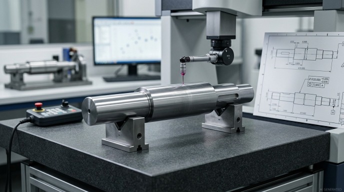
Shaft inspected for cylindricity GD&T with CMM
A shaft that measures the correct diameter at every cross-section can still fail in assembly. A bore that passes roundness inspection at five locations along its length can still cause a bearing to wear unevenly. The problem is that roundness measured at individual cross-sections does not show whether the entire surface is cylindrical. It also does not establish whether the axis is straight or whether the full surface stays within a common cylindrical form tolerance zone.
That's what cylindricity GD&T controls. controls the three-dimensional form of a cylindrical surface, including variations associated with roundness, taper, and axial curvature, and it's one of the few GD&T controls that simultaneously addresses roundness, straightness, and taper in a single measurement requirement. This guide covers what cylindricity GD&T means, how the tolerance zone works, when to specify it, how it's measured, and how it differs from related geometric controls.
What Is Cylindricity in GD&T?
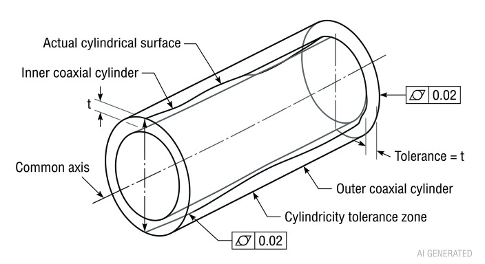
Cylindricity GD&T tolerance zone diagram
Cylindricity GD&T is a geometric form tolerance that controls how closely a physical cylindrical surface approaches a theoretically perfect cylinder. Cylindricity GD&T limits the total radial variation of all points on a cylindrical surface from a best-fit coaxial cylinder, the surface must fit between two perfectly coaxial cylinders whose radii differ by the cylindricity tolerance value.
Unlike diameter tolerances that control how large or small a cylinder is, cylindricity GD&T controls the shape of the surface. A shaft with a diameter tolerance of 25.00 ±0.025mm might be perfectly within size tolerance while still being slightly tapered (larger at one end than the other), slightly out-of-round at individual cross-sections, or curved along its axis. Cylindricity controls the three-dimensional form of the entire cylindrical surface rather than the feature's size alone.
Cylindricity Definition in One Sentence
Cylindricity GD&T limits the total radial variation of all points on a cylindrical surface from a pair of coaxial cylinders that contains the entire controlled surface , the surface must fit between two perfectly coaxial cylinders whose radii differ by the cylindricity tolerance value.
What Cylindricity Controls That Size Tolerance Doesn't
Size tolerance controls the diameter at each measured cross-section. It doesn't control:
Whether the entire surface maintains the required cylindrical form along its length
Whether each cross-section is sufficiently round; an elliptical cross-section can satisfy size limits without satisfying a separate form requirement.
Whether the entire surface maintains cylindrical form along its length; individual sections may satisfy circularity while the overall surface still has significant form variation.
Cylindricity GD&T controls all of these simultaneously. It's the difference between confirming that individual slices of a cylinder are the right size and confirming that the whole cylinder is the right shape.
Cylindricity Symbol
The cylindricity symbol in GD&T is a parallelogram shape, two angled parallel lines with two vertical lines connecting their ends, producing a shape that visually suggests a cylindrical surface viewed in perspective. It appears in the first compartment of the feature control frame, immediately identifying the callout as cylindricity.
How to Read a Cylindricity Callout
A typical cylindricity feature control frame contains the cylindricity symbol and its tolerance value:
[Cylindricity Symbol | 0.02]
That's it. No datum reference, ever. Cylindricity GD&T is a pure form control that evaluates the surface against itself, not against any external datum reference. The tolerance value (0.02 in the example above) defines the radial width of the tolerance zone. It is the difference in radius between the two coaxial cylindrical boundaries.
If a feature control frame contains the cylindricity symbol followed by a tolerance value and then a datum letter, the callout is incorrect. Adding a datum to a cylindricity callout is a fundamental drawing error, cylindricity doesn't reference datums by definition.
Example: A cylindricity callout of 0.02 mm means the controlled surface must fit within a cylindrical tolerance zone 0.02 mm wide.
Reading the Tolerance Value
The cylindricity tolerance value is not a radius, it's a total width. A cylindricity tolerance of 0.02mm means the tolerance zone is 0.02mm wide radially, not 0.02mm on each side. The outer coaxial cylinder is 0.02mm larger in radius than the inner cylinder. This is a tighter control than it might first appear. A 0.02 mm cylindricity tolerance limits the total radial separation of the cylindrical tolerance zone to 0.02 mm.
Cylindricity Tolerance Zone
The cylindricity tolerance zone is a three-dimensional region bounded by two coaxial cylinders:
- Inner cylinder radius: r
- Outer cylinder radius: r + t (where t is the cylindricity tolerance value)
- Both cylinders share the same axis and are therefore coaxial.
Every point on the controlled surface must fall within this radial band across the full length of the cylindrical feature. The tolerance zone is floating, it positions itself to best fit the actual surface being measured, finding the orientation and location that minimizes the total radial variation. The tolerance zone does not tilt independently or change shape. The two boundaries remain cylindrical and coaxial.
What the Tolerance Zone Catches
Roundness errors: If any cross-section of the surface is elliptical, lobed, or otherwise non-round, some points on that cross-section fall outside the inner or outer cylinder. The tolerance zone catches these deviations at every cross-section along the full length.
Taper: If the cylinder is larger in diameter at one end than the other, points at the larger end fall outside the outer coaxial cylinder of the best-fit zone. The tolerance zone catches gradual taper that size tolerances at individual sections might miss if each section individually conforms.
Axis curvature: If the cylinder's axis isn't straight, if the shaft has a banana-shaped bow, cross-sections at the curve fall outside the tolerance zone because their centers are displaced from the common axis of the coaxial cylinders.
Combined errors: A surface with slight taper plus slight out-of-roundness plus slight axis curvature accumulates all three deviations, and cylindricity GD&T measures the combined result. Each error contributes to the total radial variation, and the worst-case combination determines whether the surface conforms.
How Cylindricity GD&T Differs from Circularity, Straightness, and Runout
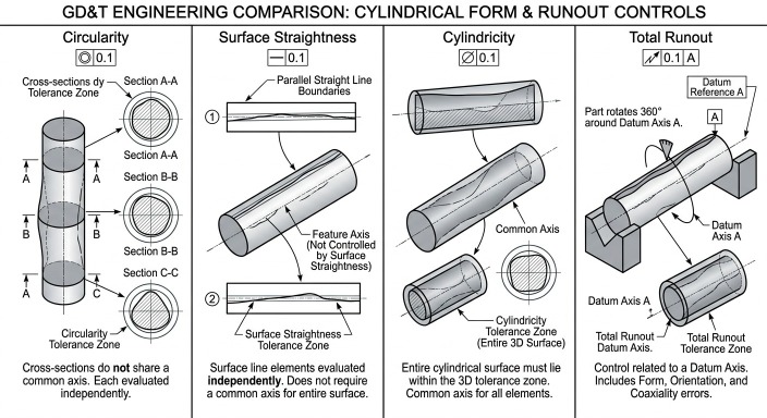
Cylindricity vs circularity, straightness, and runout
Engineers encountering cylindricity GD&T for the first time often ask why a specific control exists when circularity, straightness, and runout seem to cover similar territory. The differences are meaningful and affect both specification and inspection.
Cylindricity vs Circularity
Circularity (roundness) evaluates individual cross-sections independently. Each cross-section of the controlled feature is evaluated separately against its own best-fit circle, and the cross-sections don't need to share the same axis. A perfectly circularity-conforming shaft can have each cross-section perfectly round but shifted progressively sideways, producing a crankshaft-like helical path from end to end.
Cylindricity GD&T requires all cross-sections to share a common axis. The coaxial requirement is what separates cylindricity from circularity, it simultaneously controls the roundness of each section and the alignment of sections with each other.
| Factor | Circularity | Cylindricity GD&T |
|---|---|---|
| Scope | Single 2D cross-section | Full 3D cylindrical surface |
| Cross-section sharing | Not required | Required, all share one axis |
| Controls taper | No | Yes |
| Controls axis curvature | No | Yes |
| Datum required | No | No |
| Tolerance zone | Two concentric circles (2D) | Two coaxial cylinders (3D) |
Cylindricity vs Straightness
Straightness GD&T applied to a cylindrical surface controls individual line elements on the surface. These lines run approximately in the axial direction and are evaluated independently. Straightness doesn't require those line elements to be equidistant from a common axis. A surface where every axial line is straight but they're at varying distances from the axis (like a tapered surface with straight sides) can pass straightness while failing cylindricity.
Axis straightness, applied to the derived median line of a cylindrical feature, controls the axis itself rather than the surface. This is a different callout from surface cylindricity and serves a different engineering purpose.
Cylindricity vs Runout
Runout controls, including circular runout and total runout, require a datum reference. The surface is measured while rotating the part about the datum axis, and deviations from nominal are measured radially. Because runout references a datum axis, its result can include both surface form error and displacement relative to that datum axis, such as eccentricity.
Cylindricity GD&T has no datum. It evaluates the surface against the pair of coaxial cylinders that contains the entire controlled surface, derived from the measured surface itself. A perfectly cylindrical surface that's eccentric relative to the shaft's datum axis passes cylindricity but fails runout. This distinction is why both controls exist, they measure different things.
| Factor | Cylindricity GD&T | Total Runout |
|---|---|---|
| Datum required | No | Yes |
| What it measures | Surface form alone | Form + eccentricity + axis misalignment |
| Eccentricity effect | Excluded (best-fit removes it) | Included |
| Tolerance zone | Two coaxial cylinders (floating) | Cylindrical zone about datum axis (fixed) |
When to Specify Cylindricity GD&T
Cylindricity in engineering is specified when the three-dimensional form of a cylindrical surface, its combined roundness, taper, and axis straightness, directly affects function, and when that form must be controlled independently of the surface's position or orientation relative to datum features.
Bearing Journals and Seats
Rolling element bearings require the surfaces they seat on to be genuinely cylindrical. A tapered journal can cause the bearing's inner race to seat unevenly, creating localized contact stress and potentially accelerating fatigue. A journal that's lobed (lobing or other form errors can occur under unsuitable grinding conditions. ) produces preload variation at the bearing frequency that generates noise and accelerated wear. Cylindricity GD&T on bearing journals typically runs 0.003-0.010mm for precision applications.
Hydraulic Cylinder Bores
The bore of a hydraulic cylinder must be cylindrical for the piston seal to maintain consistent contact pressure around the circumference and along the stroke length. Out-of-cylindricity in a hydraulic bore creates leak paths at high points where the seal doesn't contact, and accelerated seal wear at low points where the seal contact pressure spikes. Cylindricity GD&T on hydraulic cylinder bores captures this three-dimensional requirement.
Precision Shafts for Sliding Fits
hafts used in precision bores, instrument spindles, measuring-machine axes, and precision guide shafts may require cylindricity control to ensure consistent clearance around the circumference and along the length of engagement. If the shaft is slightly barrel-shaped or tapered, the clearance varies with position, producing inconsistent sliding resistance and positional error.
Gauge and Reference Cylinders
Cylindrical gauge pins, master cylinders, and precision reference artefacts carry cylindricity tolerances because their entire function depends on being accurately cylindrical, they're used to verify other parts, and any form error in the gauge transfers directly to inspection error.
How Is Cylindricity Measured?
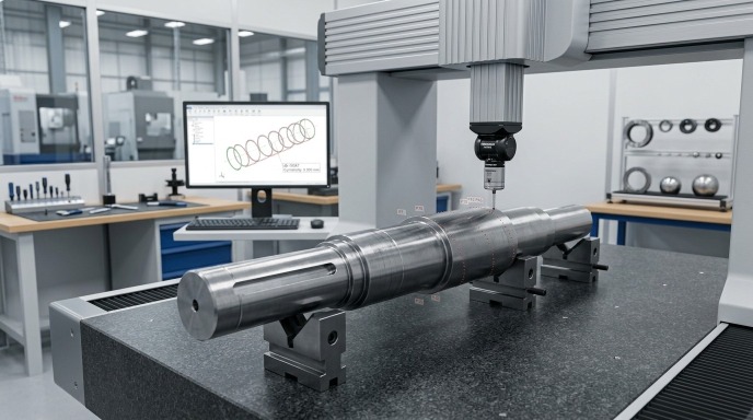
CMM measuring a cylindrical shaft
Cylindricity measurement can be demanding in precision metrology because the tolerance applies to the entire cylindrical surface rather than isolated cross-sections.
CMM Measurement
A coordinate measuring machine probes multiple points across the cylindrical surface, multiple cross-sections at multiple angular positions, distributed along the full length of the feature. The inspection software evaluates the measured point cloud against a cylindrical tolerance zone according to the applicable fitting and evaluation method.
The number of probe points affects measurement quality. Three points per cross-section detects only out-of-roundness at the measurement positions. Eight to twelve points per cross-section combined with five to ten cross-sections along the length gives a reasonable characterization of cylindricity deviation. For very tight cylindricity tolerances, probe geometry, machine calibration, environmental stability, and measurement strategy can significantly affect the result.
Roundness Measuring Instruments
Dedicated roundness and cylindricity measuring machines rotate either the part or a precision probe around a precision air-bearing spindle, collecting continuous surface data at each cross-section. By collecting data at multiple cross-sections and combining them, these instruments produce a complete cylindricity analysis with better accuracy than most CMMs can achieve.
Inspection software may use different cylinder-fitting and evaluation algorithms depending on the applicable standard and measurement procedure. THigh-end roundness and cylindricity instruments can provide very low measurement uncertainty when properly calibrated and operated under controlled conditions.
V-Block and Dial Indicator
This method does not produce a direct cylindricity value. The V-block geometry introduces an additional relationship between the measured indicator movement and the actual form error. It's appropriate for production screening on moderate-tolerance shafts but not for precision bearing journal verification.
Cylindricity in CNC Machining
Achieving Cylindricity in Turning and Grinding
CNC turning is well suited to producing cylindrical surfaces, but achievable cylindricity depends on the machine, workholding, material, geometry, thermal conditions, and process controls. Thermal effects during turning can contribute to taper and axial form variation. Part heating and uneven thermal expansion can therefore affect the measured cylindricity.
The grinding wheel follows the full length of the surface in controlled passes, and the process's light stock removal and precise force control produce cylindricity in the 0.002-0.008mm range on well-maintained equipment with proper wheel dressing.
Centerless grinding can produce good cylindricity on suitable small-diameter shafts. The achievable result depends on setup, wheel condition, workpiece geometry, and process control. Cylindricity of 0.001-0.005mm is achievable on centerless ground shafts.
How Cylindricity Tolerances Affect Machining Process Selection
| Cylindricity Requirement | Process | Notes |
|---|---|---|
| 0.050-0.100mm | Standard CNC turning | Finish pass, temperature stabilization |
| 0.010-0.050mm | Precision CNC turning or finish grinding | In-process gauging recommended |
| 0.003-0.010mm | Cylindrical grinding | Dedicated grinding machine required |
| 0.001-0.003mm | Precision cylindrical or centerless grinding | Temperature-controlled environment, calibrated wheel dressing |
| Below 0.001mm | Precision grinding + lapping | Specialist equipment, 100% inspection |
Drawing Specification for CNC Machined Parts
When specifying cylindricity GD&T on drawings for CNC machined parts, the callout leader should point directly to the cylindrical surface, not to the diameter dimension line. Attaching the feature control frame to the diameter dimension can change the intended interpretation to a derived-axis control rather than a surface control.
The cylindricity tolerance should be based on the functional requirements of the surface and then checked against the capability of the planned manufacturing process. Specifying cylindricity tighter than the process can deliver produces 100% inspection cost and high rejection rates without improving the product design. The CNC precision machining guide covers process capability by tolerance grade for CNC machining and grinding operations.
Relationship to Size Tolerance
Cylindricity and size tolerance control different characteristics. Size tolerance establishes the allowable limits of the feature of size, while cylindricity controls the three-dimensional form of the cylindrical surface. Their interaction should be evaluated under the applicable size and material-condition requirements, including Rule #1 where it applies. The cylindricity value should therefore be selected from the functional requirement rather than treated as a simple fraction of the size tolerance.
The tolerance and allowance guide covers how size tolerance and geometric tolerance interact in the broader context of specifying mating features correctly.
For features where both cylindricity and bearing fit are controlled, cylindricity GD&T works alongside the dimensional fit specification, the fit designation (H7, k6) controls size, and cylindricity controls form. Both are required for a complete specification of a precision bearing journal. The engineering fits guide covers fit designation and how it applies to bearing and shaft assemblies.
Send your CAD file and drawing to JLCCNC for a quick engineering review. We’ll check the machining process, and inspection method before production.
Upload Your Files and Get a Quote

Precision CNC Machining Service
Professional manufacturing, fast turnaround, and quality assurance.
Common Mistakes When Applying Cylindricity GD&T
Specifying Cylindricity When Runout Is Needed
If the functional requirement is that a surface runs true about a specific axis, a journal that must not wobble when the part rotates, total runout is the correct control, not cylindricity. Cylindricity GD&T evaluates form relative to a best-fit axis derived from the surface itself. Use total runout when the functional requirement is rotational accuracy relative to a datum axis. Use cylindricity when the requirement is the form of the cylindrical surface itself, independent of a datum axis.
Adding a Datum Reference
Cylindricity GD&T never has a datum. If a datum appears in the third compartment of a cylindricity feature control frame, the callout is wrong. Cylindricity is a pure form control, form is evaluated relative to the feature itself, not relative to any datum. The drawing should be corrected before production.
Applying Cylindricity to Non-Cylindrical Features
Cylindricity GD&T applies to nominally cylindrical features, surfaces intended to be cylinders. Applying it to conical features, partial cylinders, or non-cylindrical features produces a geometrically undefined tolerance that inspection can't evaluate correctly.
Setting Cylindricity Looser Than Size Tolerance
By Rule #1, cylindricity must be tighter than the total size tolerance (upper limit minus lower limit). A feature with ±0.025mm size tolerance (total tolerance band 0.050mm) cannot have a cylindricity tolerance of 0.060mm, the cylindricity zone would exceed the form requirement implied by the size tolerance itself.
Measuring Only at Cross-Sections
Measuring a cylindrical surface at multiple individual cross-sections with a roundness instrument and reporting each as passing circularity doesn't verify cylindricity. Cylindricity requires evaluation of the full three-dimensional surface, the relationship between cross-sections matters as much as the form of each individual cross-section. Only measurement methods that probe the complete surface and fit coaxial cylinders to the full dataset produce a valid cylindricity result.
FAQ About Cylindricity GD&T
Q: What is cylindricity in GD&T?
Cylindricity is a form tolerance that controls the entire three-dimensional form of a cylindrical surface within two coaxial cylindrical boundaries. It does not require a datum reference.
Q: What is the cylindricity symbol?
The cylindricity symbol is a parallelogram. It appears in the feature control frame before the specified cylindricity tolerance. It's followed only by the tolerance value with no datum reference, which visually distinguishes a cylindricity callout from orientation and runout controls that always include datum letters.
Q: How is cylindricity different from circularity?
Circularity evaluates individual two-dimensional cross-sections independently, each section is compared to its own best-fit circle without regard to whether sections share the same axis. Cylindricity GD&T evaluates the full three-dimensional surface, requiring all cross-sections to share a common axis. Cylindricity catches taper and axis curvature that circularity passes without notice.
Q: Does cylindricity require a datum?
No. Cylindricity is a form control and does not use a datum reference.
Q: What tolerance can CNC machining achieve for cylindricity?
Achievable cylindricity depends on the machine, material, geometry, workholding, thermal conditions, and inspection method. CNC turning is suitable for moderate requirements, while tighter requirements may require cylindrical or centerless grinding.
Q: When should cylindricity be specified instead of circularity?
Specify cylindricity when the form of the entire cylindrical surface matters along its length. Use circularity when the requirement is limited to the roundness of individual cross-sections
Conclusion About Cylindricity GD&T
Cylindricity is a comprehensive form control for cylindrical surfaces because it evaluates the surface along its full three-dimensional extent. The result is a single form control for evaluating whether a cylindrical surface maintains the required form along its full length.
Specifying cylindricity in machining correctly means connecting the tolerance value to a process capable of achieving it, grinding for precision applications, CMM or roundness instrument verification rather than V-block screening, and drawing callouts that point to the surface rather than the dimension line.
Keep Learning
Circularity GD&T Explained
Key Takeaways Circularity controls how round each cross-section is on a cylindrical, conical, or spherical surface. Each cross-section is checked separately. Circularity doesn't control taper, axis straightness, or alignment between sections. No datum is needed because circularity controls the shape of the feature itself. The circularity tolerance zone is bounded by two concentric circles whose radial separation equals the specified tolerance. Each circular element must fit within its own zone, evalua......
Press Fit Tolerance: Interference, Charts & Design Guide
Key Takeaways A press fit is an interference fit: the shaft is larger than the hole, and elastic deformation of the mating parts after assembly creates contact pressure that generates the friction holding the joint together. Press fit interference is the difference between the shaft diameter and the hole diameter. Minimum interference uses worst-case dimensions for the smallest overlap. Maximum interference uses worst-case dimensions for the largest overlap. Press fit tolerance is selected based on re......
GD&T Datum: Definition, Types, Symbols, and Datum Reference Frame
Key Takeaways A datum in GD&T is a theoretically exact reference used to locate or orient other features on a part. It is not the physical surface itself. A datum feature is the physical feature identified on the part and used to establish a datum. The datum itself is the theoretically exact geometric reference derived from that feature. Datums become especially important when several features have to work together. A hole pattern, bearing bore, mounting face, or mating surface may need to establish t......
GD&T Runout: Definition, Symbol, Measurement & Tolerance
Key Takeaways Runout limits surface variation while a part rotates around its specified datum axis. The datum feature establishes the axis used for the runout requirement. You compare the full indicator variation during rotation with the tolerance stated on the drawing. Circular runout applies at individual circular sections of the controlled surface. Total runout evaluates the controlled surface across its specified extent. Runout is not a size tolerance, and its value is not determined by the diamet......
GD&T Perpendicularity: Definition, Tolerance & Examples
Key Takeaways Perpendicularity is an orientation control used for a feature specified at 90° to a datum. A surface callout controls the complete surface within two parallel planes set perpendicular to the referenced datum. An axis callout controls the derived axis inside the specified tolerance zone instead of controlling the physical surface directly. Perpendicularity does not establish the location of a feature. A drawing can require another geometric control when position also needs definition. Dat......
Concentricity in GD&T: Definition, Symbol, Tolerance, and Measurement
Key Takeaways Concentricity in legacy ASME GD&T controls the derived median points of a feature relative to a datum axis. It does not simply compare the axes of two fitted cylinders. Check the drawing standard first. Legacy ASME concentricity and ISO concentricity or coaxiality should not be interpreted as equivalent requirements. For the cylindrical example in this guide, the tolerance zone is a cylinder centered on the datum axis. The derived median points of the controlled feature must lie within t......