Differences Between Tolerance and Allowance
19 min
- What Is Tolerance?
- What Is Allowance?
- Tolerance vs Allowance: What's the Difference?
- Allowance vs Clearance: Are They the Same?
- How Tolerance and Allowance Work Together
- How Tolerance and Allowance Affect CNC Machining
- Specifying Tolerance and Allowance on Engineering Drawings
- Design Guidelines for Tolerance and Allowance
- Engineering Examples of Tolerance and Allowance
- FAQs About Tolerance and Allowance
Key Takeaways
- Tolerance controls the allowable variation of a single dimension, while allowance is the intentional difference between two mating parts that determines the type of fit.
- Tolerance and allowance are closely related but describe different aspects of dimensional control. Tolerance defines the acceptable variation of a single dimension, while allowance defines the intentional difference between mating parts to achieve a required fit.
- Confuse them and you end up with parts that either won't assemble, assemble too loosely to function, or cost twice as much to make as they needed to.
Since tolerance and allowance directly affect manufacturability, experienced manufacturers review them long before machining begins. At JLCCNC, every CNC machining project goes through an engineering review to identify unnecessary precision requirements, improve manufacturability, and help reduce production cost before the first chip is cut.
What Is Tolerance?
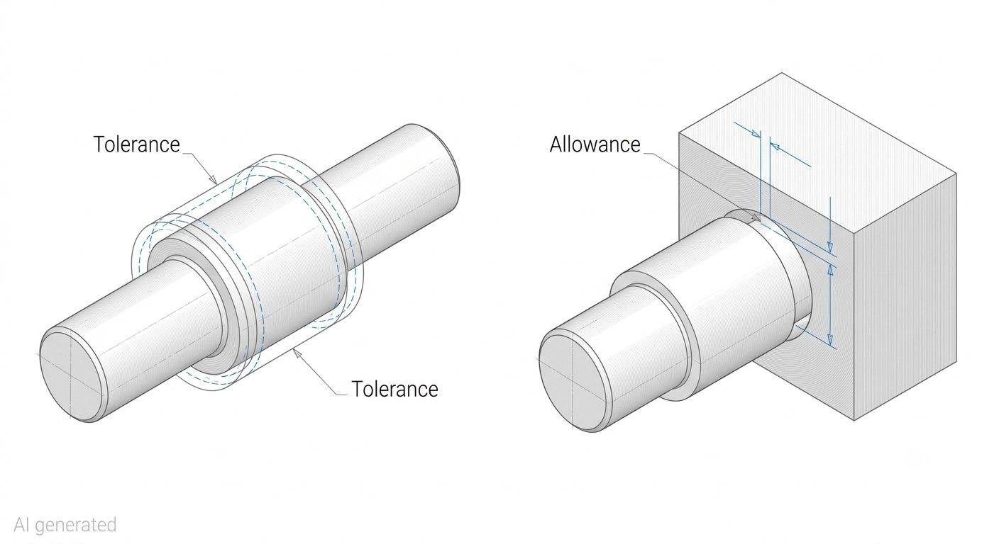
Engineering diagram showing the difference
Tolerance is the total permissible variation in a single dimension, the range between the maximum and minimum acceptable size for a feature on one part.
Every manufactured part has variation. No machining process produces exactly the same dimension twice. A part programmed to be 25.000mm comes out at 25.003mm on one pass and 24.997mm on the next. Tolerance defines how much of that natural variation is acceptable before the part fails to meet its specification.
If a shaft is dimensioned as 25.00 ±0.02mm, the tolerance is 0.04mm total. The shaft can be anywhere from 24.98mm to 25.02mm and still be within specification. Anything outside that range is rejected.
Tolerance applies to a single part in isolation. It says nothing about how that part relates to any other part. A shaft tolerance tells you what the shaft can be. It doesn't tell you how the shaft fits in a hole.
In the context of tolerance and allowance, tolerance is the manufacturing side of the equation. It reflects what the process can reliably produce, what the function requires, and the cost trade-off between precision and practicality. Tighter tolerances require more precise machining. They also increase inspection effort and production cost. Looser tolerance means faster production and lower cost, but only works if the function allows it.
Here's a full detailed guide that explains CNC machining tolerances.
What Is Allowance?
Allowance is the intentional, designed difference between the dimensions of two mating parts, set deliberately by the engineer to achieve a specific type of fit when the parts are assembled.
Where tolerance is about one part varying, allowance is about the relationship between two parts. The allowance for a shaft-and-hole assembly is the difference between the shaft's maximum material condition (largest shaft) and the hole's minimum material condition (smallest hole). This calculated value determines whether parts assemble with a gap (clearance fit), with tight friction (transition fit), or require force to assemble (interference fit).
What is allowance in engineering drawing terms? It's the numerical value that defines the intended assembly condition, usually derived from a standard fit designation like H7/g6 or H7/p6 and specified either as a calculated dimension range or directly as a fit callout in the title block or drawing note.
Allowance is set before manufacturing starts, based on how the assembly needs to behave in service. A bearing that needs to rotate freely requires a positive allowance (clearance). A bushing that needs to stay permanently in place requires a negative allowance (interference). The allowance is the functional requirement; the tolerance on each part is what the manufacturing process must achieve to deliver that functional requirement consistently.
The difference between tolerance and allowance in simple terms: tolerance is the variation you accept within one part, allowance is the gap or interference you plan between two parts.
Tolerance vs Allowance: What's the Difference?
Engineering Purpose
The engineering purpose of tolerance is to define the boundary between acceptable and unacceptable manufacturing variation on a single feature. It answers: "how much does this dimension matter, and how precisely does it need to be produced?"
The engineering purpose of allowance is to specify the intentional dimensional relationship between mating parts to achieve a defined assembly behavior. It answers: "how should these two parts fit together in the assembled product?"
These are different questions with different answers, which is why tolerance and allowance are different concepts even though both involve dimensions and both appear on engineering drawings.
Dimensional Control
Tolerance controls the dimension of a feature on a single part through the manufacturing process, it defines the acceptable window that the machining operation must hit.
Allowance controls the dimensional relationship between two features on two different parts. Neither feature's individual tolerance defines the allowance directly, the allowance comes from the combination of both parts at their maximum material conditions.
This is where the difference between tolerance and allowance becomes practically important: you can have tight tolerances on both shaft and hole and still get inconsistent allowance if the nominal dimensions are wrong. The allowance must be planned first, then tolerances assigned to each part to achieve that allowance reliably.
| Factor | Tolerance | Allowance |
|---|---|---|
| What it controls | Acceptable variation in one dimension | Intentional difference between two mating dimensions |
| Who defines it | Applied to a single part | Defined by the relationship between two parts |
| Purpose | Accounts for manufacturing variation | Determines the type of fit between components |
| Value type | Always positive (a range) | Can be positive (clearance) or negative (interference) |
| Set by | Manufacturing capability and function | Functional assembly requirement |
| Appears on drawing as | Dimensional tolerance callout | Fit designation or calculated dimension |
| Affects | How accurately one feature must be made | Whether parts assemble with gap, friction, or force |
Allowance vs Clearance: Are They the Same?
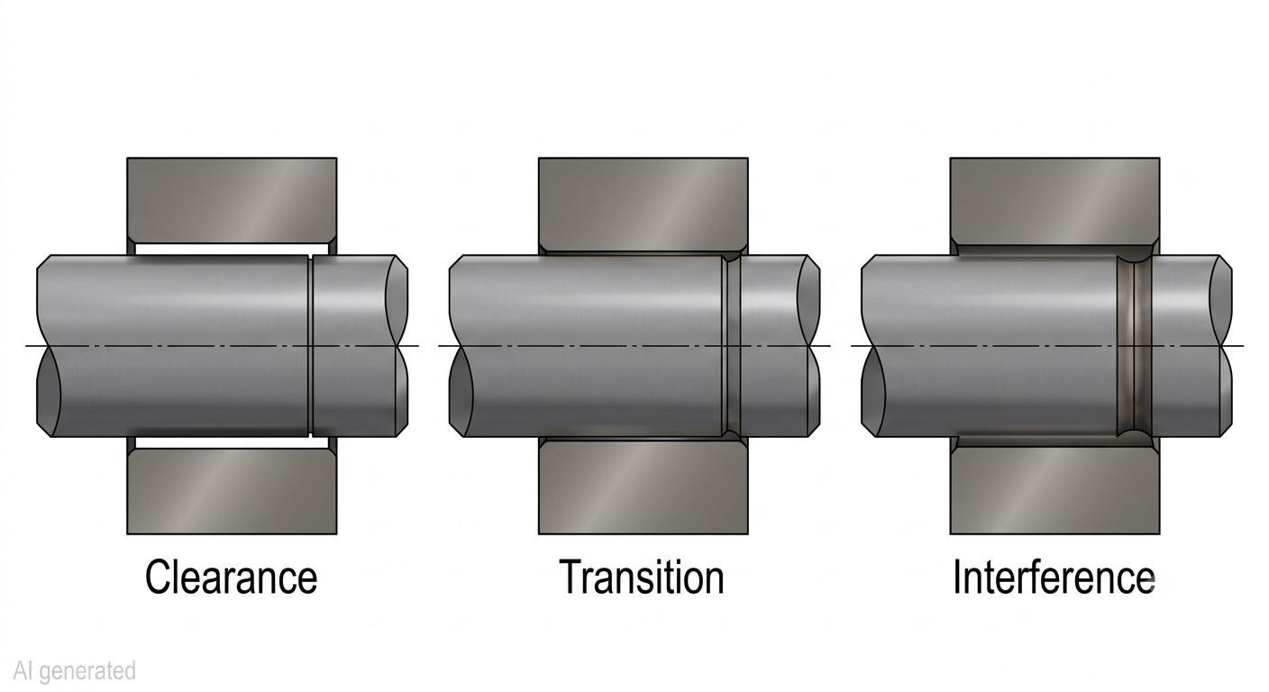
Illustration comparing clearance transition and interference fits
No. The question of whether clearance and allowance are the same things comes up frequently, and the short answer is: allowance determines the type of fit; clearance is one possible outcome of that allowance.
What Is Clearance?
Clearance is the space that exists between two assembled mating parts. When a shaft is smaller than the hole it sits in, the difference at assembly is clearance, a positive gap that allows relative motion.
Clearance exists at assembly, between actual parts. Allowance is designed in advance, based on the maximum material condition of each part. A design might specify a clearance fit with an allowance of +0.02mm (minimum clearance), meaning even at worst-case dimensions, the largest shaft and smallest hole, there's still 0.02mm of gap. The actual clearance in assembled parts will be equal to or greater than the minimum allowance because parts are rarely at their maximum material condition simultaneously.
How Allowance Influences Clearance
Allowance sets the minimum clearance (for clearance fits) or the maximum interference (for interference fits) that the design tolerances can produce. This is the designed worst-case condition.
For a clearance fit: minimum clearance = hole minimum − shaft maximum = the allowance. At all other actual dimension combinations, the clearance is larger than the allowance.
For an interference fit: maximum interference = shaft maximum − hole minimum = the (negative) allowance. The interference at actual dimensions may be less than this maximum but won't exceed it.
Clearance fits are only one category of engineering fits. See our complete guide to slip fit tolerances for practical clearance values and real machining examples.
Clearance, Transition, and Interference Fits
The relationship between allowance vs clearance: allowance is the designed value; clearance (or interference) is the physical reality at assembly. Designing the allowance correctly ensures the clearance at assembly falls within the range the application requires.
| Fit Type | Allowance | Assembly Behavior | Typical Application |
|---|---|---|---|
| Clearance fit | Positive (gap guaranteed) | Free movement | Rotating shafts, sliding components, loose assemblies |
| Transition fit | Small clearance or small interference (depending on actual dimensions) | Snug, may need light pressing | Locating features, moderate-precision assemblies |
| Interference fit | Negative (overlap) | Force or heat required to assemble | Press-fit bushings, permanent assemblies, torque transmission |
How Tolerance and Allowance Work Together
Tolerance and allowance don't operate independently, they're connected in a system that determines whether an assembly functions correctly across all manufacturing variation.
Limits, Fits, and Dimensional Variation
ISO and ASME standards formalize the tolerance and allowance relationship through fit systems. ISO 286 defines shaft and hole tolerances using letter codes (H, g, p, etc.) and grade numbers (5, 6, 7, etc.) that together specify the exact tolerance range for each feature. A callout of H7/g6 defines the hole tolerance as H7 (a specific upper deviation relative to nominal) and the shaft tolerance as g6 (a specific negative deviation). The combination of these two specified tolerances produces a designed allowance that determines the fit behavior.
This system links tolerance and allowance directly: the fit designation encodes both simultaneously, and the individual part tolerances are derived from the fit requirement rather than set independently.
Designing Mating Parts
Effective tolerance and allowance design starts with the assembly function: what does this pair of parts need to do? Rotate freely? Stay fixed? Locate accurately while still assembling without force? Once the required fit behavior is defined, the engineer selects the appropriate allowance. The tolerance on each part is then specified to ensure that allowance is achieved consistently across production, even when both parts are near their worst-case dimensions simultaneously.
For applications that require guaranteed clearance or guaranteed interference, the designed allowance should exceed the combined tolerance stack-up. A design with 0.01mm planned clearance allowance and 0.008mm tolerance on each part (0.016mm total tolerance) can produce interference at worst case. That's a design error, not a manufacturing error.
How Tolerance and Allowance Affect CNC Machining
Machining Accuracy and Process Capability
CNC machining has a natural capability range, what the process can produce reliably without special measures. Well-controlled CNC milling operations can routinely achieve around ±0.025 mm on suitable features, while general machining tolerances are often closer to ±0.05 mm. CNC turning holds ±0.010-0.025mm on most features. Grinding pushes below ±0.005mm.
Tolerance and allowance specifications need to align with what the process can do consistently. A tolerance of ±0.005mm on a milled pocket requires finish passes, in-process gauging, and controlled thermal conditions, all of which add cost. The same tolerance on a ground surface is routine. Specifying tolerance and allowance without considering the manufacturing process produces either unachievable drawings or parts that cost far more than the function requires.
Tooling, Setup, and Inspection
Tighter tolerance affects every stage of manufacturing. Setup time increases because verification becomes more rigorous. In-process measurement is required where sampling would suffice for looser tolerance. CMM inspection replaces handheld gauging. More pieces get rejected, increasing effective cost even before accounting for added process steps.
For mating parts with tight allowance requirements, gauge design becomes part of the manufacturing plan. Go/no-go gauges for shaft diameter, plug gauges for bore diameter, and functional gauges that check the assembly directly are all tools that tight tolerance and allowance requirements bring into the quality plan.
Production Cost and Lead Time
The relationship between tolerance and cost is nonlinear. Going from ±0.25mm to ±0.1mm increases cost modestly, it's achievable with standard parameters and sampling inspection. Going from ±0.1mm to ±0.025mm roughly doubles the cost in machining time and inspection. Going from ±0.025mm to ±0.005mm may triple or quadruple the cost, requiring grinding, lapping, or specialized equipment.
Allowance specifications drive cost through tolerance requirements, a tight interference fit allowance requires tight tolerances on both shaft and hole. A loose clearance allowance permits larger tolerances on both parts. Designing the allowance correctly is therefore a direct cost control decision, not just a functional one.

Precision CNC Machining Service
Professional manufacturing, fast turnaround, and quality assurance.
Specifying Tolerance and Allowance on Engineering Drawings
Dimension Tolerances
Tolerance appears on drawings as dimensional callouts: bilateral tolerance (±0.025), unilateral tolerance (+0.050/−0.000), or limit dimensions (25.025/24.975). Each format communicates the same information differently, bilateral for symmetric variation, unilateral where the part can deviate only in one direction, limits where the drawing should be unambiguous regardless of the reader's interpretation.
Fit Callouts
Allowance in engineering drawing terms is most efficiently communicated through ISO fit designations. A note calling out H7/g6 on a mating hole-shaft pair completely defines the tolerance and allowance system: anyone with ISO 286 tables can extract the exact dimension range for any nominal diameter. ASME standards use RC, LC, LT, LN, and FN fit classes that similarly encode the tolerance and allowance relationship.
Direct allowance specification is also used, explicit upper and lower limit dimensions for both shaft and hole that define the full range of possible clearance or interference across all tolerance combinations.
Engineering Drawing and CAD Conventions
Modern CAD systems link tolerance and allowance specification to the model directly, parametric tolerance tables, fit annotations, and GD&T callouts attach to the geometry rather than existing only as numbers on a flat drawing. This integration reduces interpretation errors and allows tolerance analysis to be run directly on the assembly model to verify that planned allowance produces the required fit across the full dimensional variation range.
General tolerance blocks in the title block define the default tolerance for undimensioned or un-toleranced features, these should always be checked against the tightest tolerance and allowance requirements on the drawing, which are specified individually.
Understanding projection methods also helps ensure tolerance callouts, fits, and dimensions are interpreted exactly as intended during manufacturing.
Design Guidelines for Tolerance and Allowance
Specify Only the Accuracy That Is Required
The most common and most expensive design mistake in tolerance and allowance specification is making tolerances tighter than the function requires. A fastener clearance hole doesn't need ±0.025mm, it needs to be large enough for the fastener to pass through, which ±0.5mm provides adequately. Every unnecessarily tight tolerance adds machining time, inspection time, and cost without adding functional value.
Ask for each tolerance: what happens if this feature is at the extreme of the tolerance range? If the answer is "nothing significant," the tolerance is too tight. Tighten only where function demands it.
Select Fits Based on Functional Requirements
The allowance design should start with the assembly function, not with a preference for particular fit types. A bearing inner ring needs to rotate relative to the shaft, that's a clearance fit with allowance sized for the bearing specification. A dowel pin needs to locate a part repeatably, that's a transition or light interference fit. A press-fit bushing needs to stay in place under service loads, that's an interference fit with allowance calculated from the required retention force.
Work backward from function: what behavior does the assembly need? What fit type provides that behavior? What allowance achieves that fit type? What tolerances on each part guarantee that allowance?
Consider Manufacturing Capability Early
Tolerance and allowance selection should happen in conversation with manufacturing knowledge, not in isolation. Specifying H6/p5 fit on a part that will be made on standard CNC milling equipment produces a drawing that the process can't reliably deliver. The earlier in design that manufacturing capability is factored into tolerance and allowance decisions, the less likely the design is to require expensive late-stage changes.
Engineering Examples of Tolerance and Allowance
Bearing Fits
Bearing installation is the canonical tolerance and allowance application. The bearing inner ring mounts on the shaft, the bearing outer ring mounts in the housing bore, and different applications require different fits for each interface.
A deep groove ball bearing on a rotating shaft typically uses an interference fit on the shaft (preventing inner ring creep) and a clearance fit in the housing (allowing thermal expansion). The allowance for the shaft fit might be −0.010mm to −0.025mm interference, depending on bearing size and operating conditions. The shaft tolerance might be k5 or m5. The housing tolerance might be H7. These standard designations encode both the allowance and the individual tolerances, and are specified by the bearing manufacturer for each bearing size.
Press-Fit Assemblies
A bronze bushing pressed into an aluminum housing needs to stay in place under operating loads without damaging the housing during installation. The interference allowance is calculated from the required retention force, the material properties, and the interface area. Typical interference fits for this application run 0.015-0.060mm depending on bushing diameter and retention requirement.
Each component's tolerance must be tight enough that the minimum interference (even when the bushing is at minimum and the bore is at maximum) still achieves the required retention force. If tolerance is too loose, some assembled pairs will have insufficient interference and the bushing will rotate in service.
FAQs About Tolerance and Allowance
Q: What is the difference between tolerance and allowance?
Tolerance is the permissible variation in a single part's dimension, the range between maximum and minimum acceptable size. Allowance is the intentional difference between the dimensions of two mating parts, designed to achieve a specific type of fit. Tolerance applies to one part; allowance describes the relationship between two parts. The difference between tolerance and allowance is that tolerance is about manufacturing variation control, allowance is about assembly behavior design.
Q: What is allowance in engineering?
What is allowance in engineering drawing terms is the planned difference between the maximum material condition of the shaft and the minimum material condition of the mating hole. It determines whether parts assemble with a gap (positive allowance, clearance fit), snugly (may produce slight clearance or interference), or with interference requiring force to assemble (negative allowance, interference fit). Allowance is set by the designer based on how the assembly needs to function.
Q: Are allowance and clearance the same?
No. Allowance is the intentional dimensional difference between mating parts at maximum material condition (MMC), representing the minimum clearance or maximum interference specified by the design. Clearance is the actual gap between assembled parts and varies depending on the manufactured dimensions of the hole and shaft within their tolerance limits.
Q: How does allowance affect engineering fits?
The allowance is what determines the fit type. Positive allowance produces a clearance fit with guaranteed gap. Near-zero allowance produces a transition fit that may be either a small clearance or a small interference. Negative allowance produces an interference fit requiring force or temperature change to assemble. The allowance value, combined with the tolerances on both parts, defines the full range of clearance or interference that assembled pairs will exhibit in production.
Q: Why is tolerance important in CNC machining?
Tolerance in CNC machining defines how accurately a feature must be produced and therefore what process parameters, inspection requirements, and production time are needed. Tighter tolerance and allowance specifications require slower feeds, more passes, in-process gauging, and more inspection, all of which increase cost. Understanding the tolerance and allowance requirements before machining starts determines the correct machining strategy, tooling selection, and quality control plan.
Q: How are tolerance and allowance shown on engineering drawings?
Tolerance is shown as dimensional callouts, bilateral (±0.025), unilateral (+0.05/−0.00), or limit dimensions. Allowance in engineering drawing format is typically shown as an ISO or ASME fit designation (H7/g6, RC3, etc.) in a note or on the dimension of mating features. Alternatively, explicit calculated dimension ranges for both mating parts can be specified directly, defining the allowance through the combination of the two dimensional ranges.
Q: Can tighter tolerances increase machining cost?
Yes, significantly. The relationship between tolerance and cost is nonlinear, standard tolerances of ±0.1-0.25mm are achievable with routine CNC machining. Tolerance tighter than ±0.025mm typically requires additional finishing passes, in-process measurement, and more intensive inspection. Tolerances below ±0.010mm may require grinding or other precision finishing processes. The allowance design directly drives tolerance requirements on mating parts, unnecessarily tight allowance creates unnecessarily tight tolerance, which creates unnecessary cost.
Q: How do engineers choose the right tolerance?
Tolerance and allowance selection starts with the functional requirement: what does the feature need to do, and how much variation can the function tolerate? Then compare that functional requirement against manufacturing capability, what can the specified process reliably produce? The correct tolerance is the loosest value that the function permits and the process can reliably achieve. Tighter than functional requirement wastes cost; looser than process capability creates rejects.
Precision CNC Machining Service
Professional manufacturing, fast turnaround, and quality assurance.
Conclusion About Tolerance and Allowance
Tolerance and allowance are two of the most fundamental concepts in engineering design and manufacturing, and the difference between tolerance and allowance is the difference between controlling a single part's variation and controlling two parts' assembly behavior. Both matter. Neither replaces the other.
Getting tolerance and allowance right from the start of a design saves money, reduces manufacturing problems, and produces assemblies that work consistently across production variation. Getting them wrong produces either parts that don't fit together, parts that cost twice as much as they need to, or both.
The practical takeaway: define the allowance from function first, then assign tolerances to each part to achieve that allowance reliably within the capability of the manufacturing process. Never specify tighter tolerance and allowance than the application requires. Consider manufacturing capability as early as possible in the design process rather than treating it as the machinist's problem to solve.
At JLCCNC, engineering review on every order includes tolerance and allowance feasibility assessment, identifying where specified tolerances may be tighter than the process can reliably deliver, and where allowance design may produce assembly problems before production starts.
Keep Learning
GD&T Datum: Definition, Types, Symbols, and Datum Reference Frame
Key Takeaways A datum in GD&T is a theoretically exact reference used to locate or orient other features on a part. It is not the physical surface itself. A datum feature is the physical feature identified on the part and used to establish a datum. The datum itself is the theoretically exact geometric reference derived from that feature. Datums become especially important when several features have to work together. A hole pattern, bearing bore, mounting face, or mating surface may need to establish t......
GD&T Runout: Definition, Symbol, Measurement & Tolerance
Key Takeaways Runout limits surface variation while a part rotates around its specified datum axis. The datum feature establishes the axis used for the runout requirement. You compare the full indicator variation during rotation with the tolerance stated on the drawing. Circular runout applies at individual circular sections of the controlled surface. Total runout evaluates the controlled surface across its specified extent. Runout is not a size tolerance, and its value is not determined by the diamet......
GD&T Perpendicularity: Definition, Tolerance & Examples
Key Takeaways Perpendicularity is an orientation control used for a feature specified at 90° to a datum. A surface callout controls the complete surface within two parallel planes set perpendicular to the referenced datum. An axis callout controls the derived axis inside the specified tolerance zone instead of controlling the physical surface directly. Perpendicularity does not establish the location of a feature. A drawing can require another geometric control when position also needs definition. Dat......
Concentricity in GD&T: Definition, Symbol, Tolerance, and Measurement
Key Takeaways Concentricity in legacy ASME GD&T controls the derived median points of a feature relative to a datum axis. It does not simply compare the axes of two fitted cylinders. Check the drawing standard first. Legacy ASME concentricity and ISO concentricity or coaxiality should not be interpreted as equivalent requirements. For the cylindrical example in this guide, the tolerance zone is a cylinder centered on the datum axis. The derived median points of the controlled feature must lie within t......
Engineering Fits: Clearance, Transition, and Interference Fits
Key Takeaways Engineering fits describe the dimensional relationship between two mating parts, specifically whether assembly produces clearance (gap), interference (overlap), or a result that could be either. Clearance fit always produces a gap; the shaft is always smaller than the hole. Interference fit always produces overlap; the shaft is always larger than the hole and force or temperature is needed to assemble. Transition fit can produce either a small clearance or small interference depending on......
What Is Design for X (DFX)? Principles, Types & Applications
Key Takeaways A part can work exactly as intended and still create problems in manufacturing, assembly, inspection, service, or cost. DFX brings these downstream considerations into the design stage, while design changes are still relatively easy to make. DFX principles don't replace functional requirements. They identify where those requirements create downstream problems and find ways to resolve the conflict before tooling, production, or launch. DFX is not a single method. It's a collection of over......