First Angle vs Third Angle: Understanding Orthographic Projection Methods
13 min
- What Is Orthographic Projection
- What Is First Angle Projection
- What Is Third Angle Projection
- First Angle Projection vs Third Angle Projection
- First Angle and Third Angle Projection Symbols
- First Angle and Third Angle Projection in CNC Manufacturing
- Engineering Standards for Projection Methods
- FAQ About First Angle and Third Angle Projection
Key Takeaways
- Orthographic projection is the system that lets a 3D part be represented through multiple 2D views, front, top, side, and so on.
- First angle projection and third angle projection are the two standard methods for arranging those views, and they place views in opposite positions relative to the object.
- First angle projection is the ISO standard used across most of Europe, India, China, Russia, and many other countries following ISO standards
- Third angle projection is the standard in the United States, Canada, and a few other countries following ASME conventions.
- The difference between first angle projection and third angle projection comes down to where the observer is positioned relative to the projection plane and the object.
- Getting first angle and third angle projection mixed up on a CNC manufacturing drawing produces views that are placed backwards, a genuine source of machining errors when drawings cross between regions using different standards.
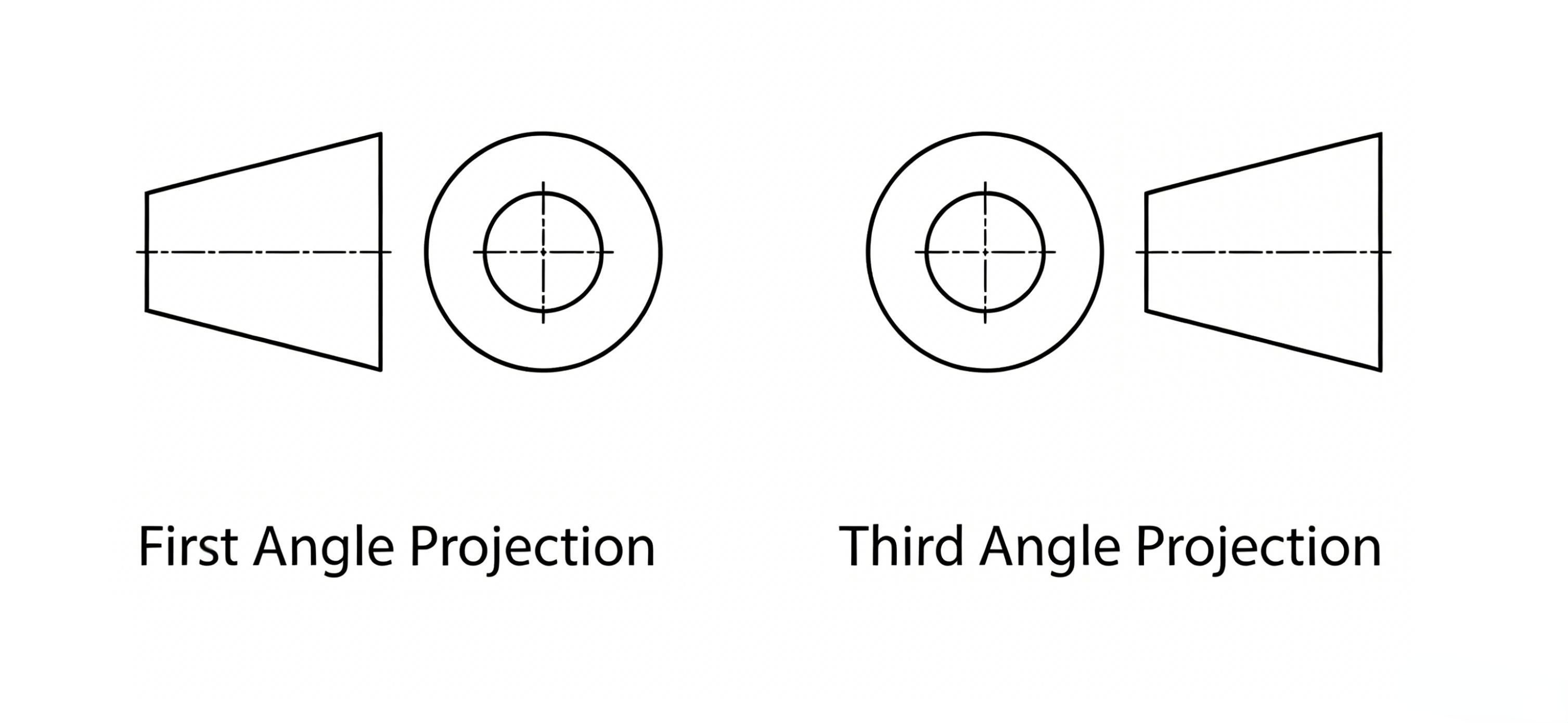
Illustration depicting first angle vs third angle
A drawing crosses the ocean, and the receiving shop machines it exactly as drawn. The part comes back wrong—not because of dimensional errors, but because no one noticed whether the drawing used first angle or third angle projection. These two methods arrange views in mirror-opposite layouts, and confusing them can produce parts that are geometrically reversed.
This kind of error is more common than it might appear admit. In this guide, you'll be learning what first angle projection and third angle projection actually are...
At JLCCNC, drawings are checked against production standards before machining, including projection method and view clarity. This helps reduce avoidable manufacturing errors when first angle and third angle drawings move between regions.

Precision CNC Machining Service
Professional manufacturing, fast turnaround, and quality assurance.
How to tell them apart quickly, and why this distinction matters every single time a drawing crosses borders.
What Is Orthographic Projection
(ResearchGate) Orthographic projection
Definition of Orthographic Projection
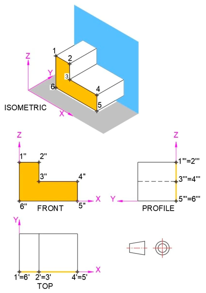
Orthographic projection is a method of representing a three-dimensional object using multiple two-dimensional views, each one looking straight at the object from a different direction — front, top, side, and sometimes additional angles — with all the lines of sight running parallel to each other and perpendicular to the viewing plane.
Why Orthographic Projection Is Used in Engineering Drawings
A single 2D image of a 3D object loses information. A photograph from one angle hides the back, bottom, and side features. Orthographic projection solves this by providing several flat views, each capturing geometry that the others cannot show. Together, these views describe the part fully and unambiguously.
This is why every engineering drawing relies on orthographic projection as its foundation. Whether the drawing uses first angle projection or third angle projection, the underlying idea is the same: multiple flat views, each showing a different face of the object, arranged in a standardized layout that lets anyone trained on that standard read the part's geometry correctly.
What Is First Angle Projection
(cube cad academy) first angle projection
How First Angle Projection Works
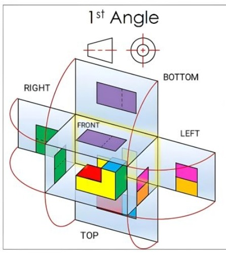
In first angle projection, the object sits between the observer and the projection plane. Think of the part floating in space, with a flat plane behind it. The observer stands in front of the part and looks through it toward the plane. Because the object sits between the observer and the plane, the projected view appears flipped relative to an intuitive layout.
The practical result is that, in first angle projection, the top view is placed below the front view, and the right-side view is placed to the left of the front view.ahj his feels backwards to anyone used to the opposite convention, which is exactly why knowing which system a drawing uses matters before you start interpreting it.
View Placement in First Angle Projection
Standard view arrangement in first angle projection: the front view sits in the center. The top view goes directly underneath the front view, as if the top of the object has been "folded down" onto the page below the front view. The view from the right side of the object is placed to the left of the front view, and the view from the left side is placed to the right.
This arrangement can feel counterintuitive at first, but it follows directly from the geometry: the object sits between the viewer and the plane, so each view falls onto the opposite side of the plane relative to the viewing direction.
What Is Third Angle Projection
(cube cad academy) third angle projection
How Third Angle Projection Works
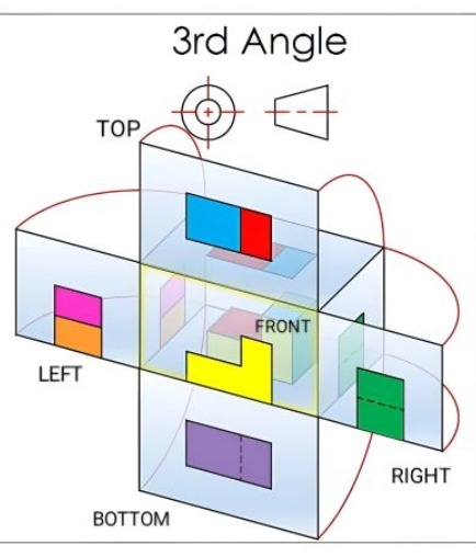
In third angle projection, the projection plane sits between the observer and the object — as if the observer looks through a transparent plane at the part beyond it. Picture the part floating in space, with a flat transparent plane positioned between you and the part, the view that appears on that plane is the projection. Because the plane is closer to the observer than the object, the projected view lands in a position that matches the viewing direction more intuitively.
The practical result: in third angle projection, the top view is placed above the front view, and the right-side view is placed to the right of the front view. This matches how most people instinctively expect views to be arranged, which view is "above" corresponds to looking from above, and the view that's "to the right" corresponds to looking from the right side.
View Placement in Third Angle Projection
Standard view arrangement in third angle projection: the front view sits in the center. The top view is placed directly above the front view, as if the top of the object has been "folded up and back" onto the page above the front view. The view from the right side of the object is placed to the right of the front view, and the view from the left side is placed to the left.
This arrangement is often called more intuitive because each view's position on the page matches the direction from which the object is viewed. Walk to the right side of the part, and that view appears on the right.
First Angle Projection vs Third Angle Projection
View Arrangement Differences
The core difference in first angle projection vs third angle projection is where each view lands relative to the front view. the third angle system, the top view goes below and the right-side view goes left. In the first angle method, the top view goes above and the right-side view goes right. Every other view in the standard six-view layout follows the same mirrored logic, the former and the latter projection place views in exactly opposite positions relative to the central front view.
| View Position | First Angle Projection | Third Angle Projection |
|---|---|---|
| Top view | Below front view | Above front view |
| Bottom view | Above front view | Below front view |
| Right-side view | Left of front view | Right of front view |
| Left-side view | Right of front view | Left of front view |
| Rear view | Typically to the right of left-side view | Typically to the right of right-side view |
Projection Plane Concept Comparison
The conceptual difference comes down to the relative positions of the observer, the object, and the projection plane. In first angle projection, the sequence is observer → object → plane: the object is between you and where the image forms. In third angle projection, the sequence is observer → plane → object: the plane is between you and the part, like looking through a window.
This single conceptual difference is the root cause of every view-placement difference between the two systems. Once you understand which side of the object the plane sits on, the entire view arrangement for that projection method follows logically.
Common Sources of Drawing Misinterpretation
The most common mistake is failing to check which projection system a specific drawing uses before interpreting it. A machinist trained on third angle projection who receives a first angle drawing may read the top view as the bottom view and vice versa. On a symmetric part, this error might go unnoticed. On an asymmetric part, it produces a mirrored geometry that does not match the design intent.
Another common error is assuming the projection method based solely on country of origin. Even though first angle projection dominates in many regions and third angle projection is standard in North America, individual companies — especially multinationals — may specify their own standard regardless of location.
First Angle vs Third Angle Projection: Key Differences
| Aspect | First Angle Projection | Third Angle Projection |
|---|---|---|
| Observer–Object–Plane order | Observer → Object → Plane | Observer → Plane → Object |
| Top view position | Below the front view | Above the front view |
| Right-side view position | Left of the front view | Right of the front view |
| Left-side view position | Right of the front view | Left of the front view |
| Bottom view position | Above the front view | Below the front view |
| Rear view position | Typically to the right of the left-side view | Typically to the right of the right-side view |
| Dominant standard | ISO (Europe, India, China, Russia, much of Asia) | ASME Y14.3 (USA, Canada) |
| Symbol | Truncated cone oriented per first angle convention | Same shape, reversed orientation |
First Angle and Third Angle Projection Symbols
The first angle and third angle projection symbols use the same basic shape — a truncated cone or cylinder — but oriented oppositely. Each symbol appears in or near the title block and is the definitive indicator of which projection system the drawing follows. Someone familiar with both can distinguish them at a glance.
How to Identify Projection Methods on Technical Drawings
The fastest way to identify the projection method is to check the title block for the projection symbol. If no symbol is present, check the drawing standard noted in the title block: ISO standards default to first angle projection, while ASME defaults to third angle. If neither the symbol nor the standard is indicated, the most reliable check is to look at the actual view arrangement. A top view below the front means first angle projection. A top view above the front means third angle projection. This geometric check works regardless of missing symbols or standards.it's based on the direct geometric output of whichever projection method was used.
First Angle and Third Angle Projection in CNC Manufacturing
CNC Machining Drawing Requirements
In CNC machining, the drawing is the contract between design intent and the physical part. Both first angle and third angle projection can fully describe the same geometry. What differs is how that geometry is arranged on the page, and the CNC programmer must correctly map the views back to 3D before programming toolpaths.
For parts with features on multiple faces, counterbores on one side, a pocket on another, a stepped profile that only makes sense from a specific view, misreading first angle projection as third angle projection (or the reverse) can result in features being programmed on the wrong face of the part entirely.
Preventing Manufacturing Errors
The safeguard against projection errors is straightforward: check the projection symbol before programming, every time, regardless of where the drawing originated. For shops working with international customers, both projection methods appear regularly. Treating the symbol check as a standard first step in drawing review — alongside units, tolerances, and material — catches problems before any material is cut.
For asymmetric parts specifically, a quick mental cross-check helps: does the view arrangement on the drawing match what first angle projection or third angle projection would produce for this geometry? If the top view position doesn't match the projection symbol's implied system, that's a red flag worth resolving before cutting any material.
Communication Between Designers and Manufacturers
When drawings come from different regions, confirming the projection method during quote review or DFM feedback removes ambiguity before production starts. A brief note such as "this drawing uses first angle projection, confirming our interpretation matches your intent" costs little and eliminates one of the most avoidable causes of first-article rejections on international orders.
Engineering Standards for Projection Methods
ISO Standards and First Angle Projection
ISO 128 and related standards specify first angle projection as the default. Drawings created under ISO conventions throughout Europe and much of Asia follow first angle unless explicitly noted otherwise. For shops working primarily with European or Asian customers, first angle is standard drawing literacy.
ASME Standards and Third Angle Projection
ASME Y14.3 governs multiview and sectional view drawings under the American standard, and it specifies third angle projection as the default. North American manufacturers and customers working under ASME conventions will typically produce third angle projection drawings, and this is the system most commonly taught in North American technical education as the baseline.
Global Engineering Drawing Practices
Globally, both systems are used regularly, and neither is technically superior. Both are equally capable of describing any geometry. What matters for manufacturing is consistency and clarity: the projection symbol should be present, it should match the actual view layout, and anyone reading the drawing should check rather than assume.
FAQ About First Angle and Third Angle Projection
Q: What is the difference between first angle projection and third angle projection?
The difference is where the projection plane sits relative to the object and observer. In first angle projection, the object is between the observer and the plane, which places the top view below the front view and the right-side view to the left. In third angle projection, the plane is between the observer and the object, which places the top view above the front view and the right-side view to the right. Both systems fully describe the same geometry, they just arrange the views in mirror-opposite positions.
Q: Which countries use first angle projection?
First angle projection is the standard under ISO drawing conventions and is widely used across Europe, India, China, Russia, and much of Asia. It's the default for drawings created under ISO 128 and related international standards, though individual companies may specify either system regardless of regional convention.
Q: Which countries use third angle projection?
Third angle projection is the standard under ASME Y14.3 and is the dominant convention in the United States, Canada and Japan. It's the default taught in North American technical and engineering education and is widely used by manufacturers and designers working under American drawing standards.
Q: How can I identify the projection method on a drawing?
Check the title block for the projection symbol, a small graphic based on a truncated cone or cylinder, oriented differently for first angle projection versus third angle projection. If no symbol is present, check whether the drawing standard noted (ISO typically means first angle, ASME typically means third angle) gives a clue. As a final check, look at where the top view sits relative to the front view: below means first angle projection, above means third angle projection.
Q: Why is orthographic projection important in CNC manufacturing?
Orthographic projection is how 3D part geometry gets communicated through 2D drawings, and CNC manufacturing depends entirely on correctly interpreting those drawings to program toolpaths. Whether a drawing uses first angle projection or third angle projection doesn't change the part's geometry, but misreading which system is in use can cause features to be mapped onto the wrong face of the part, producing a machined part that's geometrically mirrored from the design intent, even though every individual dimension was read correctly.
Q: Do CNC machining services accept both first angle and third angle drawings?
Yes, both standards are commonly used. The important step is confirming the projection symbol and drawing standard before machining.
Popular Articles
• Cutting with Precision: A Comprehensive Guide to CNC Water Jet Technology
• CNC Coolant Explained: Types, Maintenance & Safety
• Rake Angle in Machining: Machinists’ Guide to Perfect Cuts
• What Steps Are Taken To Minimize Waste In CNC Machining Processes?
• How EDM Wire Cutting Works: Complete Guide to Precision CNC Wire Cutting
Keep Learning
Chatter in Machining: Causes, Effects, and How to Reduce It
CNC milling operation producing visible chatter marks on an aluminum workpiece Quick Chatter Diagnosis Checklist Symptom Most Likely Cause First Action High-pitched squeal Regenerative chatter Change spindle speed ±15% Chatter only in deep pockets Excessive tool overhang Shorten tool Chatter on thin walls Low workpiece rigidity Improve fixturing Chatter after tool replacement Runout / holder issue Check tool holder Chatter only during finishing DOC too small / rubbing Increase feed or adjust speed It ......
What Is Tool Offset in CNC? Types, Setup & Best Practices
CNC tool offset setup with measurement overlay Key Takeaways CNC offsets connect programmed intent with actual cutter position. Length data guides Z-axis depth control. Radius data protects part size during contour milling. Geometry values define the cutter's measured baseline. Wear values support fine correction during production. Verified data lowers scrap risk before full machining. Good offset habits protect tools, fixtures, and parts. In the context of CNC machining , tool offset is the quiet set......
Trochoidal Milling: Complete Guide to High-Efficiency CNC Machining
Key Takeaways Trochoidal milling combines circular cutter motion with continuous forward feed. The cutter normally engages 5 to 20% of its diameter instead of making a full-width cut. A smaller engagement angle limits force changes during slotting and pocket roughing. Low radial engagement often allows greater axial depths of cut than conventional slot milling. CAM software calculates the circular path automatically from the selected machining parameters. This strategy is widely applied to titanium, s......
What Is Die Casting? Process, Materials, and Applications
Key Takeaways Die casting is a metal casting process that forces molten metal into a reusable steel mold under high pressure, producing parts with tight tolerances and good surface finish at high volume. Aluminum die casting is the most common form by far, thanks to its combination of light weight, decent strength, and good corrosion resistance. The die casting process runs through mold preparation, injection, cooling, and ejection in a cycle that can repeat every few seconds to minutes depending on p......
First Angle vs Third Angle: Understanding Orthographic Projection Methods
Key Takeaways Orthographic projection is the system that lets a 3D part be represented through multiple 2D views, front, top, side, and so on. First angle projection and third angle projection are the two standard methods for arranging those views, and they place views in opposite positions relative to the object. First angle projection is the ISO standard used across most of Europe, India, China, Russia, and many other countries following ISO standards Third angle projection is the standard in the Un......
Micro EDM Machining: Capabilities, Materials, and Applications for Precision Components
Key Takeaways About Micro EDM Machining Only electrically conductive materials can be machined. Hole diameters can reach below 50 μm on specialized equipment. The process produces almost no mechanical cutting force, making it suitable for thin or delicate features. Surface integrity still requires attention because recast layers and heat-affected zones may remain after machining. Micro EDM is often combined with CNC machining, with milling producing the main geometry before EDM finishes critical micro......