Press Fit Tolerance: Interference, Charts & Design Guide
20 min
- What Is a Press Fit?
- Press Fit Tolerance Chart
- How to Choose a Press Fit Tolerance
- How Press Fit Tolerances Affect CNC Machining
- Common Press Fit Problems and Solutions
- Press Fit Tolerance FAQs
- Conclusion About Press Fit Tolerance
Key Takeaways
- A press fit is an interference fit: the shaft is larger than the hole, and elastic deformation of the mating parts after assembly creates contact pressure that generates the friction holding the joint together.
- Press fit interference is the difference between the shaft diameter and the hole diameter. Minimum interference uses worst-case dimensions for the smallest overlap. Maximum interference uses worst-case dimensions for the largest overlap.
- Press fit tolerance is selected based on required holding force, material properties, and assembly method, not from a single universal rule.
- ISO fit designations like H7/p6 and H7/s6 encode the press fit tolerance for each part in a standardized notation used on engineering drawings.
- CNC machining for press fit applications requires tight dimensional control, appropriate surface finish, and verified inspection before assembly, because interference that's outside tolerance can't be corrected once the parts are assembled.
A press fit is an interference fit in which the shaft is intentionally larger than the mating hole. Assembly force or thermal expansion brings the two components together, and the resulting elastic deformation creates contact pressure at the interface.
The selected press fit tolerance defines the possible interference range between the mating parts, while the actual interference, material properties, geometry, and operating conditions determine the resulting contact pressure. Insufficient interference can allow relative motion under load, while excessive interference can increase assembly force, local stress, permanent bore deformation, or hub cracking.
This guide covers how press fit interference works, how to calculate it, how to read a press fit tolerance chart, and what CNC machining needs to produce and verify press fit dimensions reliably.
What Is a Press Fit?
A press fit is an interference-fit joint in which a shaft or external feature is assembled into a slightly smaller bore or internal feature.
How Interference Creates a Press Fit
When a shaft larger than the bore is forced into the hole, both parts deform elastically. The hole expands slightly; the shaft compresses slightly. The diametral interference is accommodated by elastic deformation of the shaft and hub, with the amount of deformation carried by each component depending on its material, geometry, and stiffness. After assembly, the mating parts remain elastically deformed by the interference, creating a residual contact pressure at the interface. The result is a radial contact pressure distributed around the interface, and that contact pressure, multiplied by friction, is what creates the axial and rotational holding force.
Within the elastic operating range, increasing interference generally increases contact pressure and frictional holding capacity. However, excessive interference can increase assembly force, hoop stress, and the risk of permanent deformation or cracking.
Press Fit vs Clearance and Transition Fit
| Fit Type | Shaft vs Hole | Assembly | Relative Motion | Typical Use |
|---|---|---|---|---|
| Clearance fit | Shaft always smaller | Easy, hand or light guidance | Allowed (rotation/sliding) | Bearings, sliding components |
| Transition fit | May be larger or smaller | Hand or light mallet | Limited or controlled motion | Locating pins, dowels |
| Press fit (interference) | Shaft always larger | Force required | Relative motion resisted by friction | Permanent joints, bushings, bearing races |
For a closer look at how clearance fits are specified and controlled in CNC machining, see our guide to slip fit tolerances.
How Press Fit Interference Is Calculated
This press fit calculation is based on the tolerance limits of the mating hole and shaft.
Press fit interference is not a single value; it is a range defined by the dimensional limits of the mating features. The actual interference in any assembled pair depends on where both parts fall within their respective tolerance ranges.
For a diametral press fit, the basic formula:
Interference = Shaft Diameter − Hole Diameter
Applied to dimensional limits:
Minimum Interference = Minimum Shaft Diameter − Maximum Hole Diameter
Maximum Interference = Maximum Shaft Diameter − Minimum Hole Diameter
Minimum and Maximum Interference
Minimum interference is the smallest overlap that can result from assembly, it occurs when the shaft is at its smallest acceptable dimension and the hole is at its largest. This is the worst-case condition for joint strength: minimum contact pressure, minimum holding force.
Maximum interference is the largest overlap that can result. It occurs when the shaft is at its largest acceptable dimension, and the hole is at its smallest. This is the worst-case condition for assembly: maximum press force required, highest stress in both parts.
Both values matter. Minimum interference must be large enough to provide the required holding force. Maximum interference must be small enough that assembly doesn't yield the material or require a press force that damages the components.
Example of Press Fit Interference Calculation
Consider a 30mm nominal diameter press fit joint with the following limits from an H7/p6 designation:
Hole (30 H7): 30.000mm to 30.021 mm; Shaft (30 p6): 30.022mm to 30.035mm
Minimum interference = 30.022 − 30.021 = 0.001mm Maximum interference = 30.035 − 30.000 = 0.035mm
This is a light interference fit with a very small worst-case interference. Whether it provides sufficient retention depends on the load, materials, geometry, and operating conditions. The minimum interference of 0.001mm is marginal for many load cases. For a stronger press fit on the same 30mm basic size, moving to H7/s6 gives a shaft range of 30.035mm to 30.048mm:
Minimum interference = 30.035 − 30.021 = 0.014mm Maximum interference = 30.048 − 30.000 = 0.048mm
The s6 designation provides a higher interference range than p6 at the same basic size and may be appropriate where greater retention is required, subject to verification of material stress, assembly force, and operating conditions.
Press Fit Tolerance Chart
How to Read a Press Fit Tolerance Chart
A press fit tolerance chart maps basic size ranges to the actual dimensional limits that result from a given fit designation. The chart has three key columns: the nominal size range it applies to, the hole limits, and the shaft limits. From these, minimum and maximum interference can be calculated directly.
The tolerance grade number (6, 7, 8 in designations like p6 or H7) indicates the size of the tolerance band. Lower numbers mean tighter tolerance bands, which narrow the range between minimum and maximum interference and give more predictable assembly results.
Common ISO Fit Designations for Press Fits
| ISO Designation | Fit Type | Interference Range at Ø25 mm | Typical Assembly Method | Example Applications |
|---|---|---|---|---|
| H7/p6 | Light interference fit | 0.001–0.035 mm | Press or controlled assembly | Light retention, bushings |
| H7/r6 | Medium interference fit | 0.007–0.041 mm | Press fit | Hubs, bushings, moderate loads |
| H7/s6 | Strong interference fit | 0.014–0.048 mm | Press or shrink fit | Permanent assemblies, higher loads |
| H7/t6 | Heavy interference fit | 0.020–0.054 mm | Heavy press or shrink fit | High-load hubs and couplings |
| H7/u6 | Very heavy interference fit | 0.027–0.061 mm | Usually shrink fit | Heavy-duty permanent assemblies |
Values are based on ISO 286 fit classes at the stated nominal diameter and reference temperature.
Press Fit Tolerance Chart
H7/p6 Interference Range by Nominal Diameter
| Nominal Size Range (mm) | H7 Hole Limits | p6 Shaft Limits | Min Interference | Max Interference |
|---|---|---|---|---|
| 6-10 | +0 / +0.015 | +0.015 / +0.024 | 0.000mm | 0.024mm |
| 10-18 | +0 / +0.018 | +0.018 / +0.029 | 0.000mm | 0.029mm |
| 18-30 | +0 / +0.021 | +0.022 / +0.035 | 0.001mm | 0.035mm |
| 30-50 | +0 / +0.025 | +0.026 / +0.042 | 0.001mm | 0.042mm |
| 50-80 | +0 / +0.030 | +0.032 / +0.051 | 0.002mm | 0.051mm |
| 80-120 | +0 / +0.035 | +0.037 / +0.059 | 0.002mm | 0.059mm |
The stated values are tolerance-stack interference, not a universal assembly-force specification. Confirm hub stress, bore wall thickness, material condition, surface finish and coating before releasing the fit.
Hole-Basis and Shaft-Basis Systems
ISO press fit tolerances are most commonly specified in the hole-basis system, the hole is fixed at H tolerance (lower deviation at basic size) and the shaft deviation is varied to achieve the required interference. The hole-basis system is widely used because the H hole establishes a standard reference zone, while different shaft tolerance zones can be selected to obtain clearance, transition, or interference fits. Standard drilling, reaming, boring, and finishing processes also make it practical to control holes around standard nominal sizes.
The shaft-basis system fixes the shaft tolerance zone and varies the hole deviation. It is useful when the shaft diameter is constrained by standard ground stock, a motor shaft, a bearing-related dimension, or another non-negotiable interface.
How to Choose a Press Fit Tolerance
The fit designation defines the allowable dimensional relationship between the mating features. The resulting interference is what determines the mechanical condition of the assembled joint.
There is no universal interference value for a press fit. As a starting point, ISO fit classes such as H7/p6 provide relatively low interference, while H7/s6 or H7/u6 provide progressively higher interference. The required value must then be verified against material strength, hub geometry, engagement length, operating temperature, friction, and assembly method.
For initial selection, use the lowest interference class that satisfies the required holding force and stress limits, then verify the worst-case interference and assembly method before finalizing the fit.
Required Holding Force and Load
Start by quantifying what the press fit needs to resist. Axial pull-out loads, radial shear forces, and torque each engage the interference joint differently. Axial holding force depends on interface pressure, friction coefficient, shaft diameter, and engagement length. Under a simplified uniform-pressure model, F≈μpπdL. Torque capacity depends on the same variables and also increases with the effective interface radius.
For a lightly loaded locating feature, a low-interference fit such as H7/p6 may be appropriate, but the required interference should still be checked against the materials, assembly method, and required retention force. If the fit must transmit significant torque, a gear hub, a coupling, or a pulley, the interference must produce enough contact pressure that friction exceeds the applied torque with an appropriate safety factor.
Interference, Contact Pressure, and Assembly Force
Higher interference produces higher contact pressure at the interface, which increases both the joint's holding capacity and the force required to assemble it. The Lamé equations for thick-walled cylinders relate interference to contact pressure for a given material and geometry. For critical interference-fit designs, contact pressure and component stress should be verified using an appropriate analytical model, such as Lamé-based thick-wall cylinder equations, rather than selecting interference from a generic rule of thumb.
For a given diameter, surface condition, and coefficient of friction, press-in force is approximately proportional to interface contact pressure and engagement length. Under the same diameter, interference, surface condition, and friction assumptions, doubling the engagement length approximately doubles the required press force.
Maximum assembly force must stay within what the fixture, press equipment, and parts themselves can safely handle. Excessive press force can produce stresses at the bore that exceed the allowable material stress, particularly in brittle cast iron or hardened components, increasing the risk of cracking or permanent deformation.
Material and Operating Temperature
Material pairing changes the required interference in two ways. First, softer materials can undergo local plastic deformation or asperity flattening under high contact pressure, which can reduce the effective interference and contact pressure over time. For softer hub materials such as aluminum or brass, interference should be checked against the allowable contact pressure and hub stress rather than increased automatically. Excessive interference can cause local yielding, bore distortion, or cracking during assembly.
Second, different thermal expansion coefficients between shaft and hub change the effective press fit interference at operating temperature. A steel shaft in an aluminum housing, with aluminum expanding at roughly twice steel's rate, reduces interference as the assembly heats up. At elevated temperature, what began as an adequate press fit may become insufficient for the load. Press fit tolerance selection for mixed-material assemblies must verify interference remains adequate at maximum operating temperature.
Assembly Method and Required Fit Strength
The assembly method constrains the practical interference range. Room-temperature press fitting requires sufficient press capacity, rigid fixturing, accurate alignment, and controlled insertion speed. As interference increases, the required assembly force and component stress also increase. For larger interference values, shrink fitting can reduce assembly force by temporarily expanding the hub or contracting the shaft before assembly. The final interference should be checked against the calculated assembly force, material stress, and available equipment rather than selected solely by fit designation.
Shrink fitting, heating the hub to expand it before assembly, then allowing it to cool on the shaft, allows much larger interference to be assembled without press force, because the thermal expansion temporarily creates clearance. Thermal assembly can make higher-interference fits, including H7/u6-class fits in suitable applications, practical when direct pressing would require excessive force or create unacceptable assembly stresses.
For press-fit components, JLCCNC can review fit callouts and critical dimensions from the 2D drawing and apply tighter machining tolerances where the part geometry and manufacturing requirements allow.
Upload your CAD file and 2D drawing to have the specified fit, tolerance, and critical mating dimensions reviewed for manufacturing.

Precision CNC Machining Service
Professional manufacturing, fast turnaround, and quality assurance.
How Press Fit Tolerances Affect CNC Machining
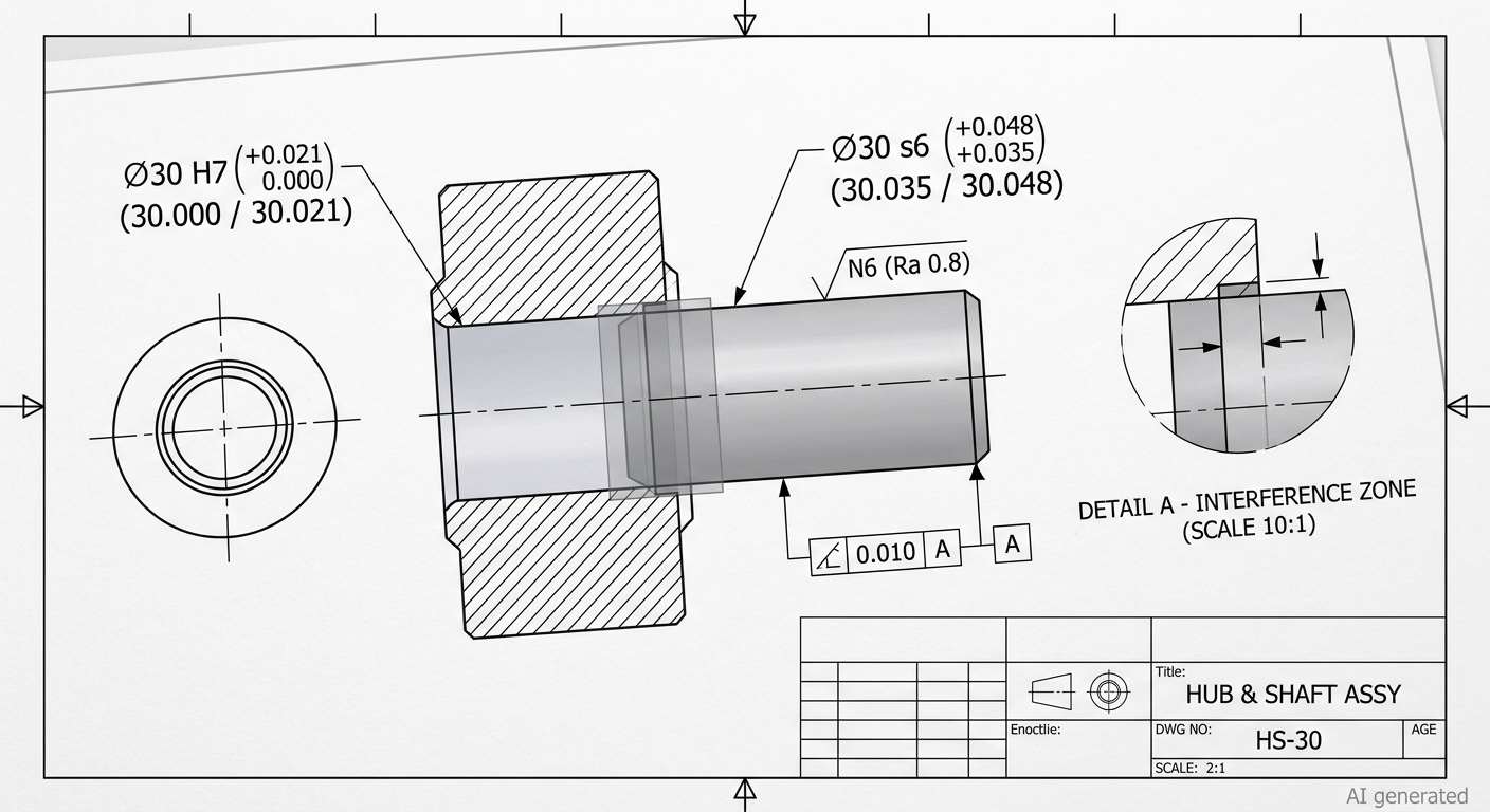
Drawing close-up showing how a press fit is specified
Controlling Mating Feature Dimensions
Press fit tolerances are among the tighter dimensional requirements in standard CNC machining. The total tolerance band for an IT6 or IT7 feature at 25mm diameter is 13µm and 21µm respectively, ranges where every process parameter that affects dimensional output becomes significant.
For shafts and bores, the required tolerance grade determines the finishing process. Tight IT7 features may be achievable through controlled CNC turning, boring, or reaming, while tighter IT6 features may require additional finishing such as precision boring, honing, or grinding depending on the material, diameter, geometry, and production requirements.
For more detail on producing precision diameters, bearing seats, runout, and surface finish on shafts, see our guide to shaft machining.
For production press fits, the target is not simply to measure one part within tolerance. The machining process should be centered within the allowable interference window and capable of maintaining that window as tool wear, machine temperature, material behavior, and batch conditions change. A bore that measures 30.010mm at the start of a run and drifts to 30.025mm after fifty parts due to tool wear produces a batch with highly variable press fit interference, some pairs near minimum interference, others near maximum.
For more on how tolerance control works in practice during CNC machining, the CNC probing guide covers on-machine measurement that catches dimensional drift before it affects finished parts.
Surface Finish and Coatings
Surface finish on press fit mating surfaces affects both the assembly behavior and the effective interference. Rough surfaces have higher asperity peaks that compress during press assembly, the effective interference is slightly less than the dimensional interference because some of the overlap is taken up by surface peak deformation rather than elastic bulk deformation.
Ra 0.8–1.6 µm is a commonly specified range for many machined press-fit surfaces, although the appropriate finish depends on the interference, material pairing, lubrication, assembly method, and functional requirements. Finer finishes such as Ra 0.4 µm may be appropriate for precision press fits where surface asperity deformation and assembly consistency are critical.
Anodizing, plating, and other surface treatments can change the finished dimensions of mating features. The dimensional change depends on coating thickness, coating type, process conditions, and whether the feature is internal or external. For anodizing, coating thickness should not be treated as the same value as dimensional buildup: part of the oxide penetrates the substrate while the remainder grows outward. As a practical design approximation, Type II anodizing is often treated as roughly one-third outward growth and two-thirds penetration, while Type III hardcoat is closer to a 50/50 split.
For a critical press-fit feature, the drawing should clearly define whether the fit dimension applies before or after coating. The machining allowance should then be based on the expected finished dimension rather than simply subtracting the full coating thickness.
How to Specify a Press Fit on a Drawing
A press-fit drawing should specify the basic size and fit designation, such as Ø30 H7 and Ø30 s6, with explicit limit dimensions added when they improve manufacturing or inspection clarity. The applicable fit standard should also be clear where needed.
Example for a 30mm press fit:
- Hole: Ø30 H7 (30.000 / 30.021)
- Shaft: Ø30 s6 (30.035 / 30.048)
Surface finish callouts belong on the mating surfaces, not just on the general tolerance note. Geometric controls such as roundness, cylindricity, runout, or position may be required when the press fit also controls rotation, alignment, or concentricity. The selected GD&T control should reflect the actual functional requirement of the mating features.
Inspection Before Assembly
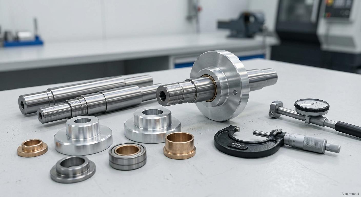
finished CNC-machined press-fit components
Once a press-fit assembly is completed, direct access to the mating dimensions is lost, so non-conforming dimensions should be identified before assembly whenever possible. Depending on the interference and component design, some press fits can be disassembled using heating, cooling, or controlled extraction methods, but damage remains possible.
For critical press-fit features, 100% inspection may be appropriate when the fit directly affects assembly or functional safety. For stable production processes, sampling may be appropriate when supported by process capability data, the control plan, customer requirements, and the criticality of the fit.
Bore gauges and outside micrometers with calibrated uncertainty appropriate to the tolerance band verify both shaft and hole before any pair is committed to assembly. For a bore, the GO plug gauge should pass through the feature under the specified gauging conditions, while the NO-GO gauge should not enter beyond its acceptance limit. For a shaft, the GO ring gauge should pass over the feature, while the NO-GO gauge should not.
Common Press Fit Problems and Solutions
| Problem | Cause | Effect | Solution |
|---|---|---|---|
| Excessive assembly force, hub cracking | Maximum interference exceeds material yield at bore | Hub fracture during assembly, bore permanently distorted | Verify maximum interference against calculated yield stress; switch to shrink fitting for large interference; check dimensional compliance before assembly |
| Joint slips under load | Insufficient interference, minimum interference too small | Relative motion between shaft and hub, fretting corrosion, accelerated wear | Increase interference by moving to higher fit class (p6→s6); verify minimum interference meets calculated holding force requirement |
| Variable assembly force across batch | Wide dimensional variation in shaft or bore diameter | Inconsistent joint quality, some pairs over-stressed, others under-retained | Tighten process control, verify process capability, and adjust the tolerance allocation or fit class only after confirming that the required interference range justifies the tighter specification. |
| Joint loosens at operating temperature | Differential thermal expansion reduces interference | Loss of retention at elevated temperature, joint failure in service | Calculate interference at operating temperature for both materials; increase room-temperature interference to compensate for thermal loss |
| Bore out-of-round after assembly | Press fit stress on thin-walled hub exceeded elastic limit locally | Bound bearing race, loss of roundness in bore affecting mating function | Increase hub wall thickness; reduce interference; use shrink fitting to reduce stress concentration at entry |
| Surface damage on assembly | Rough mating surfaces, no lead chamfer, misalignment | Galling, material transfer, bore scoring | Add a suitable lead-in chamfer to the shaft and bore to guide assembly and reduce edge damage, with the chamfer size selected according to the part diameter, wall thickness, and available engagement length. |
| Fretting corrosion at interface | Micro-motion from cyclically varying load despite interference | Oxidized debris at interface, loss of effective contact area, noise | Eliminate excessive micro-motion by reviewing interference, contact pressure, joint stiffness, and service loads; use an approved surface treatment or anti-fretting compound only when compatible with the required friction and assembly conditions. |
Press Fit Tolerance FAQs
Q: What is a press fit?
A press fit is an interference fit: an assembly in which the shaft diameter is larger than the hole diameter. Force is required for assembly, and the resulting elastic contact stress between the parts resists relative motion.
Q: What is press fit interference?
Press fit interference is the dimensional difference between the shaft diameter and the bore diameter—the amount by which the shaft exceeds the hole. Once the parts are assembled, this interference creates radial contact pressure and the friction that holds the joint. The interference range runs from a minimum, based on the smallest shaft and largest hole, to a maximum, based on the largest shaft and smallest hole within their tolerances.
Q: What tolerance is used for a press fit?
Common ISO press-fit selections include H7/p6 for lower interference, H7/s6 for higher-interference drive fits, and H7/u6 for heavy interference where thermal assembly may be appropriate. The correct fit depends on holding force, material, interference range, part geometry, and the assembly method. There is no universal press-fit tolerance.
Q: How do you calculate press fit interference?
Calculate press fit interference as: Interference = Shaft Diameter − Hole Diameter. For the tolerance limits, minimum interference = shaft minimum limit − hole maximum limit; maximum interference = shaft maximum limit − hole minimum limit. For example, a 30 mm H7/s6 fit has a minimum interference of 0.014 mm and a maximum interference of 0.048 mm. The actual assembly pair will fall within this range.
Q: How much interference is needed for a press fit?
There is no universal interference value for a press fit. At the same nominal diameter, H7/p6 produces relatively low interference, while H7/s6 and H7/u6 provide progressively higher interference. Check the proposed range against the applied load, material strength, hub geometry, operating temperature, and assembly method.
Q: What is the difference between press fit and shrink fit?
Both methods create an interference fit, but they assemble the components differently. A press fit forces the shaft into the bore at room temperature and is practical for moderate interference. Shrink fitting heats the hub to expand the bore, or cools the shaft to reduce its diameter, so the parts can be assembled with clearance. After temperatures equalize, the intended interference develops. This method accommodates larger interference values without the press force and misalignment risk of room-temperature assembly.
Precision CNC Machining Service
Professional manufacturing, fast turnaround, and quality assurance.
Conclusion About Press Fit Tolerance
A reliable press fit starts with an interference range that suits the application. The fit must provide enough contact pressure to prevent unwanted movement without creating excessive stress during assembly or operation. Material properties, operating temperature, and the way the parts will be assembled all affect the final tolerance choice.
For CNC-machined press-fit parts, the specified dimensions also need to be achievable and verifiable in production. Critical mating features should be defined clearly on the drawing and checked in the finished condition before assembly, particularly when the interference range is narrow.
JLCCNC can review press fit callouts and critical dimensions as part of the CNC machining process. Upload your CAD files and drawings to request a DFM review and CNC machining quote.
Keep Learning
Circularity GD&T Explained
Key Takeaways Circularity controls how round each cross-section is on a cylindrical, conical, or spherical surface. Each cross-section is checked separately. Circularity doesn't control taper, axis straightness, or alignment between sections. No datum is needed because circularity controls the shape of the feature itself. The circularity tolerance zone is bounded by two concentric circles whose radial separation equals the specified tolerance. Each circular element must fit within its own zone, evalua......
Press Fit Tolerance: Interference, Charts & Design Guide
Key Takeaways A press fit is an interference fit: the shaft is larger than the hole, and elastic deformation of the mating parts after assembly creates contact pressure that generates the friction holding the joint together. Press fit interference is the difference between the shaft diameter and the hole diameter. Minimum interference uses worst-case dimensions for the smallest overlap. Maximum interference uses worst-case dimensions for the largest overlap. Press fit tolerance is selected based on re......
GD&T Datum: Definition, Types, Symbols, and Datum Reference Frame
Key Takeaways A datum in GD&T is a theoretically exact reference used to locate or orient other features on a part. It is not the physical surface itself. A datum feature is the physical feature identified on the part and used to establish a datum. The datum itself is the theoretically exact geometric reference derived from that feature. Datums become especially important when several features have to work together. A hole pattern, bearing bore, mounting face, or mating surface may need to establish t......
GD&T Runout: Definition, Symbol, Measurement & Tolerance
Key Takeaways Runout limits surface variation while a part rotates around its specified datum axis. The datum feature establishes the axis used for the runout requirement. You compare the full indicator variation during rotation with the tolerance stated on the drawing. Circular runout applies at individual circular sections of the controlled surface. Total runout evaluates the controlled surface across its specified extent. Runout is not a size tolerance, and its value is not determined by the diamet......
GD&T Perpendicularity: Definition, Tolerance & Examples
Key Takeaways Perpendicularity is an orientation control used for a feature specified at 90° to a datum. A surface callout controls the complete surface within two parallel planes set perpendicular to the referenced datum. An axis callout controls the derived axis inside the specified tolerance zone instead of controlling the physical surface directly. Perpendicularity does not establish the location of a feature. A drawing can require another geometric control when position also needs definition. Dat......
Concentricity in GD&T: Definition, Symbol, Tolerance, and Measurement
Key Takeaways Concentricity in legacy ASME GD&T controls the derived median points of a feature relative to a datum axis. It does not simply compare the axes of two fitted cylinders. Check the drawing standard first. Legacy ASME concentricity and ISO concentricity or coaxiality should not be interpreted as equivalent requirements. For the cylindrical example in this guide, the tolerance zone is a cylinder centered on the datum axis. The derived median points of the controlled feature must lie within t......