Engineering Fits: Clearance, Transition, and Interference Fits
19 min
- What Are the Types of Fit in Engineering?
- How Tolerances Define Engineering Fits
- How to Choose the Right Engineering Fit
- How Engineering Fits Are Specified on Drawings
- CNC Machining Considerations for Engineering Fits
- Applications of Engineering Fits in CNC Machined Parts
- Engineering Fits FAQs
- Conclusion About Engineering Fits
Key Takeaways
- Engineering fits describe the dimensional relationship between two mating parts, specifically whether assembly produces clearance (gap), interference (overlap), or a result that could be either.
- Clearance fit always produces a gap; the shaft is always smaller than the hole. Interference fit always produces overlap; the shaft is always larger than the hole and force or temperature is needed to assemble.
- Transition fit can produce either a small clearance or small interference depending on where actual dimensions fall within their tolerance ranges.
- Fits in mechanical engineering are specified on engineering drawings using standardized systems such as ISO 286 and ASME B4.1/B4.2, depending on the applicable standard.
- CNC machining achieves tight engineering fits through appropriate process selection, turning and milling for general fits, grinding and honing for precision bearing fits.
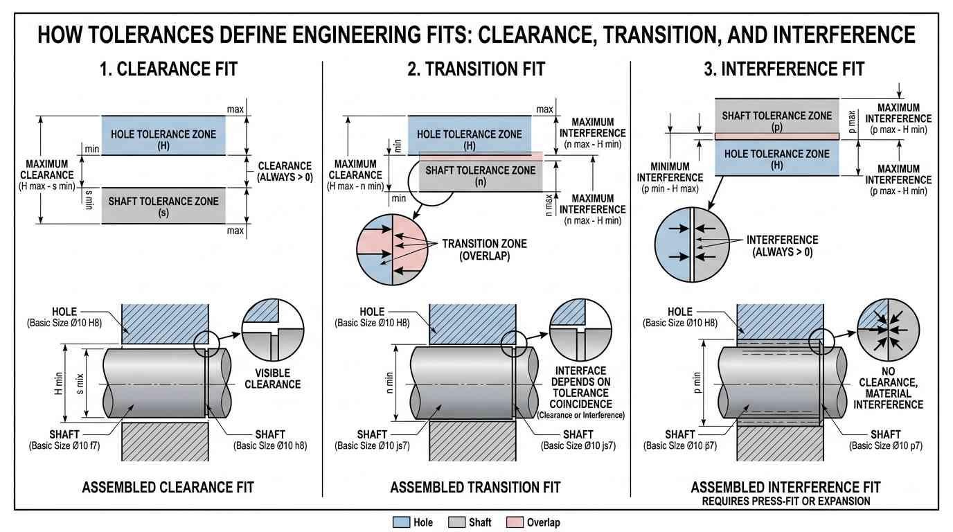
Engineering fits tolerance zones showing clearance, transition, and interference fits
An engineering fit defines the dimensional relationship between two mating features, typically a hole and a shaft. Depending on the specified tolerance zones, the assembly may allow relative movement, require interference for retention, or provide controlled positioning between the components.
The selected fit directly affects assembly force, relative movement, retention, and service performance. An incorrect fit can cause excessive clearance, interference, assembly difficulty, or premature component wear.
JLCCNC produces CNC-machined components to engineering fit specifications across industries, from bearing housings requiring precise interference fits to locating pins needing controlled clearance.
Understanding the fit requirement helps engineers specify the mating dimensions clearly and select a manufacturing process that can achieve them consistently.

Precision CNC Machining Service
Professional manufacturing, fast turnaround, and quality assurance.
What Are the Types of Fit in Engineering?
Engineering fits classify the dimensional relationship between two mating parts as clearance, interference, or transition, based on the relative positions of their tolerance zones.
Clearance Fit
A clearance fit guarantees a gap between mating parts in every possible assembly combination. Even at worst-case dimensions, largest shaft paired with smallest hole, a clearance fit still produces space between the surfaces. This gap allows relative motion: sliding, rotating, or translating without binding.
The amount of clearance isn't fixed. It varies between the minimum clearance (smallest gap, at worst-case dimensions) and maximum clearance (largest gap, at best-case dimensions). A plain-bearing or sliding-bushing assembly may use a clearance fit sized to maintain the required running clearance under operating conditions, including thermal expansion and lubrication effects.
Clearance fits range from very loose (significant gap, used where coarse alignment is sufficient) to close-running (minimal gap, used where accurate guidance is required with free relative motion).
Interference Fit
An interference fit, sometimes called a press fit or force fit, guarantees overlap between mating surfaces in every assembly combination. The shaft is always larger than the hole, which means material must be compressed or the parts must be temperature-differential assembled to achieve assembly at all.
Once assembled, the interference creates a friction grip that resists both axial and rotational movement. A bushing pressed into a housing bore relies on this interference to stay in position under service loads. A gear pressed onto a shaft transmits torque through the interference contact.
The interference amount, how much the shaft exceeds the hole, determines the assembly force required and the retention force the joint provides. Too little interference and the joint slips under load. Too much and assembly damages the parts or exceeds the material's yield stress at the contact surface.
Transition Fit
A transition fit occupies the territory between clearance and interference. At maximum material conditions, largest shaft, smallest hole, a small interference results. At minimum material conditions, smallest shaft, largest hole, a small clearance results. A transition fit gives the designer no guarantee of which outcome any specific assembled pair will produce.
This behavior is intentional and is useful when accurate positioning is required without committing to a permanent interference fit. Transition fits are used for locating features where the part needs to be positioned accurately and held in place, but where precise torque transmission or permanent retention isn't required. A locating pin in a fixture, a dowel in a housing, a hub on a shaft where a keyway carries the torque load- these use transition fits to provide accurate positioning with assembly that's possible by hand or light mallet.
How Tolerances Define Engineering Fits
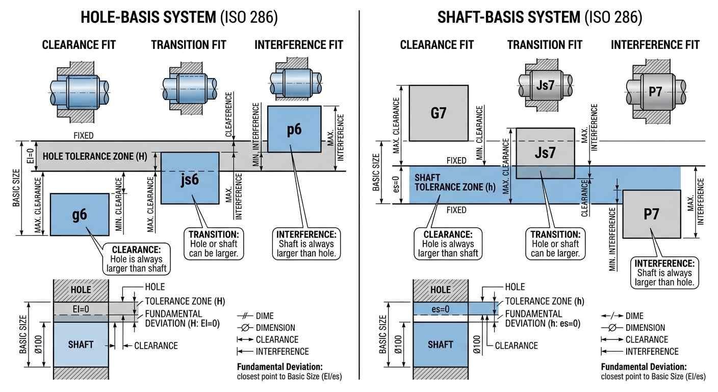
Hole-basis and shaft-basis systems for engineering fits
A fit is not a single dimensional value. It is a range of possible assembly conditions determined by the tolerances of both mating features.
Basic Size, Limits, and Tolerance Zones
A feature is defined by its basic size and permissible limits of size. The upper limit is the largest acceptable size, while the lower limit is the smallest acceptable size. The difference between these two limits is the total tolerance allowed for the feature.
For a shaft and hole assembly, the fit condition depends on the relationship between the tolerance zones of both parts. If the shaft's entire tolerance zone falls below the hole's tolerance zone, every dimensional combination produces clearance. If the shaft's zone falls entirely above the hole's zone, interference fit results in every combination. If the tolerance zones overlap, the fit is a transition fit: some dimensional combinations produce clearance, while others produce interference.
These calculations allow the designer to verify whether the specified tolerances will produce the intended assembly condition.
Hole-Basis and Shaft-Basis Systems
ISO 286, the international standard for fits and clearances, uses two complementary systems for specifying engineering fits.
In the hole-basis system, the lower deviation of the hole is zero, so the minimum hole size equals the basic size. Different shaft tolerance positions are then selected to obtain the required fit. The hole-basis system is widely used because standard tooling and finishing processes make it practical to maintain a controlled hole size, while the shaft diameter can often be varied more easily to obtain different fits.
In the shaft-basis system, the shaft dimension is fixed and the hole adjusts to produce the fit. This system is used when standard-diameter shafts (ground bar stock, precision shaft standards) drive the design, and the housing or hub bore is machined to match.
How Clearance Is Determined Between Mating Parts
For a clearance fit:
Minimum clearance = minimum hole size − maximum shaft size
Maximum clearance = maximum hole size − minimum shaft size
For an interference fit:
Minimum interference = minimum shaft size − maximum hole size
Maximum interference = maximum shaft size − minimum hole size
These calculations define the functional range the fit must deliver, and they're what engineers use to verify that the specified tolerances actually produce the intended assembly behavior before a part ever reaches the machine.
How to Choose the Right Engineering Fit
These examples are typical starting points rather than universal fit recommendations. The final fit should be selected from the required load, movement, materials, temperature, assembly method, and applicable standard.
| Fit Type | Typical Clearance/Interference | Assembly Method | Typical Application |
|---|---|---|---|
| Loose running (H11/c11) | Large clearance | Hand | Non-precision fits, large temperature variation |
| Free running (H9/d9) | Moderate clearance | Hand | Rotating shafts in plain bearings |
| Close running (H8/f7) | Small clearance | Hand | Precision running fits, spindles |
| Sliding (H7/g6) | Very small clearance | Hand | Sliding without free rotation |
| Locational clearance (H7/h6) | Near zero clearance | Hand | Accurate location, easily assembled |
| Locational transition (H7/k6) | Small clearance or interference | Hand/light mallet | Accurate location, moderate retention |
| Locational interference (H7/p6) | Small interference | Press | Permanent location, light load |
| Medium drive (H7/s6) | Moderate interference | Press | Bushings, drive fits with light torque |
| Force fit (H7/u6) | Large interference | Press/temperature | High retention, permanent assemblies |
Movement and Positioning Requirements
The first question in fit selection: does the joint need to allow relative motion, prevent relative motion, or simply position parts accurately without transmitting load?
| Requirement | Typical fit |
|---|---|
| Allow relative motion | Clearance fit |
| Prevent relative motion | Interference fit |
| Locate parts accurately while allowing assembly | Transition fit or locational clearance fit |
Load and Assembly Requirements
The magnitude and direction of service loads determine how much interference or clearance is appropriate. A lightly loaded locating dowel needs much less interference than a heavily loaded press-fit hub. The required interference depends on the load case, contact geometry, material properties, friction, engagement length, and allowable assembly stress. Axial retention and torque transmission should be evaluated separately because they impose different requirements on the joint.
The assembly method also constrains the practical interference range. A fit requiring 50 kN of press force, for example, may require a hydraulic press and a suitable fixture. A fit requiring hand assembly limits interference to values a person can realistically achieve without tooling damage.
Material and Operating Conditions
Material combination affects the contact pressure, deformation, and allowable interference of a fit. A softer component may deform more under the same interference, so the fit should be checked against the material's yield strength and the required retention force rather than selecting interference from material hardness alone. Different thermal expansion rates between mating materials change the effective clearance or interference at operating temperature relative to room temperature assembly conditions.
A steel shaft in an aluminum housing expands the housing bore more than the shaft at elevated temperature, which reduces interference in a press fit or increases clearance in a running fit. Fits in mechanical engineering that operate across significant temperature ranges need analysis at both assembly temperature and operating temperature to confirm fit function at both conditions.
For CNC-machined parts, fit requirements should be reviewed before production to confirm that the specified tolerance is compatible with the part geometry and manufacturing process. JLCCNC can review fit specifications during the quoting process and identify requirements that may need additional finishing or inspection.
Precision CNC Machining Service
Upload your files for engineering review and quote at JLCCNC.
How Engineering Fits Are Specified on Drawings
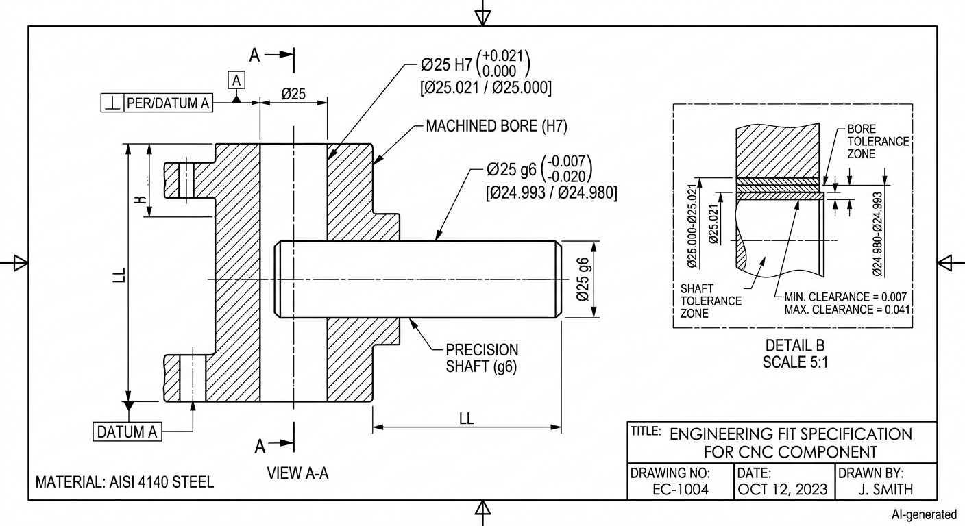
Engineering fits specified with H7 and g6 tolerance callouts on a mechanical drawing
Fit Designations and Tolerance Classes
ISO 286 specifies fits using a letter-number code applied to the basic size. For a hole: uppercase letters identify the fundamental deviation, numbers identify the tolerance grade. For a shaft: lowercase letters and numbers follow the same pattern.
A complete fit callout for a 30mm diameter bearing seat might read:
- Hole: 30 H7 → H = zero fundamental deviation from basic size (hole basis); 7 = IT7 tolerance grade
- Shaft: 30 k6 → k = small positive fundamental deviation; 6 = IT6 tolerance grade
The combination H7/k6 produces a transition fit. For a 30 mm basic size, the typical limits are 30.000–30.021 mm for the H7 hole and 30.002–30.015 mm for the k6 shaft. This gives a maximum clearance of 0.019 mm and a maximum interference of 0.015 mm, so the actual assembly can result in either clearance or interference.
ASME B4.1 uses a different system of fit classes, including RC, LC, LT, LN, and FN, to define clearance, transition, and interference relationships for specified size ranges.
Reading Hole and Shaft Callouts
A drawing with a hole callout of Ø25H7 specifies a 25mm basic size hole with H fundamental deviation and IT7 tolerance grade. From tolerance tables, for 25mm nominal diameter, IT7 = 21µm. H fundamental deviation = 0 (lower limit at basic size). Therefore: hole limits are 25.000mm to 25.021mm.
A mating shaft callout of Ø25g6 specifies: g fundamental deviation = -7µm below basic size, IT6 = 13µm. Therefore: shaft limits are 24.993mm to 24.980mm.
Maximum clearance = 25.021 - 24.980 = 0.041mm. Minimum clearance = 25.000 - 24.993 = 0.007mm. This is a close-running clearance fit appropriate for precision spindles and sliding mechanisms.
This calculation shows how the fit designation translates into the actual dimensional limits of the mating parts.
Drawing Requirements for CNC Machined Fits
For CNC machined parts, the most useful fit specifications include the basic size with fit designation (H7/g6), the resulting limit dimensions for each part (25.000/25.021 for the hole; 24.993/24.980 for the shaft), and any surface finish requirement on the mating surfaces.
Stating the limit dimensions alongside the fit designation removes ambiguity, the machinist doesn't need ISO tables to verify the part meets specification. The inspection department can measure directly against stated limits rather than looking up what H7 means for a 25mm diameter.
CNC Machining Considerations for Engineering Fits
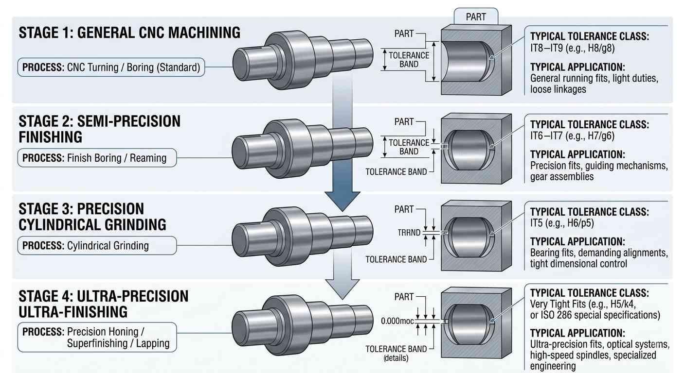
CNC machining process capability for precision engineering fits
For CNC-machined parts, the specified fit must be translated into achievable feature tolerances and an appropriate finishing process. The tighter the fit requirement, the more important process capability, thermal control, and inspection become.
Selecting Machining Processes for Fit Requirements
Different CNC processes have different natural process capabilities, and matching the process to the fit requirement avoids unnecessary cost.
Standard CNC turning and boring can achieve the dimensional accuracy required for many general engineering fits, but actual capability depends on the machine, material, feature geometry, process conditions, and inspection method. For tighter IT6–IT7 fits, additional finishing operations such as reaming, finish boring, or grinding may be required depending on the feature and required tolerance.
Very tight tolerances in the IT5 range and below often require controlled finishing processes such as precision grinding, honing, or other specialized finishing methods. The appropriate process depends on the feature geometry, material, tolerance, surface finish, and production volume.
This approach helps engineers specify only the tolerance required by the function, avoiding unnecessary machining and inspection costs.
For a detailed discussion of surface finish requirements that often accompany tight fit specifications, see the straightness GD&T guide and GD&T flatness guide, both of which address the geometric controls that appear alongside dimensional fit specifications on precision part drawings.
Designing Parts with Manufacturable Fit Requirements
An engineering fit can fail to perform as intended because of an incorrect specification or because the part geometry makes the specified tolerance difficult to manufacture.
Long interference fits, where the engagement length is many times the diameter, require more precise alignment during press-fit assembly and generate higher peak stress at entry. Chamfers at the entry of press-fit bores reduce this stress concentration and guide parts into alignment.
Thin-walled housings for interference fits distort under the press force, which changes the bore geometry after assembly. Wall thickness should be sufficient that the housing can absorb the interference stress without exceeding yield at the bore surface.
Blind holes for interference fits trap air during assembly, generating hydraulic back-pressure that resists seating. A small vent groove or flat on the shaft relieves this pressure and allows full seating without requiring excessive press force.
The design for cost guide covers broader DFM principles that apply to tolerance specification across CNC machined parts, including why applying tight fit tolerances only where the function demands them is a direct manufacturing cost control decision.
Inspecting Machined Fits
Verification of engineering fits in production uses measurement methods matched to the tolerance band being checked.
For IT8-IT9 range fits: outside micrometers for shafts, bore gauges or internal micrometers for holes. Measurement uncertainty of a calibrated micrometer is approximately ±0.002mm, adequate for tolerances of 0.025-0.05mm.
For IT6–IT7 fits, bore gauges, air gauges, or other suitable precision measurement systems may be used depending on the feature size and inspection requirements. The measurement system should provide adequate resolution and uncertainty relative to the tolerance being verified. Go/no-go gauges verify conformance directly without requiring dimensional measurement. The go gauge must enter the bore (or pass over the shaft), and the no-go gauge must not.
For very tight tolerances, precision gauging, calibrated CMM measurement, or specialized form-measurement equipment may be appropriate. At these tolerance levels, temperature control and measurement uncertainty become increasingly important.
The CNC probing guide covers on-machine probing that verifies fit-critical dimensions during the machining operation rather than at a separate inspection stage, catching dimensional issues while the part is still in the fixture and correction is still possible.
Applications of Engineering Fits in CNC Machined Parts
| Application | Fit Type | ISO Designation (typical) | Why This Fit |
|---|---|---|---|
| Deep groove ball bearing, rotating | Interference (shaft) + Clearance (housing) | k5/H7 | Inner race grips shaft; outer race floats for thermal expansion |
| Plain bearing (sleeve bearing) | Clearance | H8/f7 | Free rotation with controlled oil film gap |
| Locating dowel pin | Transition | H7/n6 | Accurate position, hand-removable for maintenance |
| Press-fit bushing in housing | Interference | H7/s6 | Permanent retention under vibration |
| Sliding machine tool component | Clearance | H7/g6 | Precise guidance with free sliding motion |
| Gear keyway hub | Transition | H7/js6 | Accurate positioning; key carries torque |
| Precision spindle bearing | Interference | H5/k4 | Controlled preload, minimal runout |
| Removable cover locating boss | Clearance | H9/e8 | Easy assembly/disassembly, adequate location |
Bearing and Shaft Assemblies
The interference fit between a rolling element bearing's inner race and its shaft is one of the most precisely specified fits in mechanical engineering. The shaft must be large enough to prevent inner race creep under load, a spinning inner race that fretting-corrodes the shaft surface fails quickly. But excessive interference prestresses the bearing, reducing its load capacity and fatigue life.
Standard bearing manufacturers publish recommended shaft and housing tolerances for each bearing series and load condition. For a 6205 deep groove ball bearing, the recommended shaft and housing fits depend on factors such as which ring rotates relative to the load, load magnitude, operating temperature, and mounting conditions. Bearing manufacturers provide fit recommendations for specific operating conditions.
An H7 housing bore is commonly used in some bearing arrangements, but the appropriate housing fit depends on the bearing ring loading, operating conditions, and whether axial displacement is required to accommodate thermal expansion.
Locating Features and Press-Fit Components
Dowel pins locate mating components, fixture plates, motor mounts, split housings, with repeatable accuracy across repeated assembly and disassembly cycles. The fit between dowel and bore must be tight enough for accurate location but loose enough to allow removal without damage.
H7/n6 is the standard locating transition fit for this application, assembled pairs produce small interference or small clearance, and the average result gives accurate location. Depending on the design, the pin may be installed with a light press and removed using a suitable extraction method when service access is required.
Press-fit bushings in housings use heavier interference (H7/s6 or H7/u6 for high-retention applications) because they must stay in position permanently under the shock and vibration loads that service life imposes. The interference must be sufficient that the bushing never loosens without being so large that it distorts the bore geometry or requires a press force that risks housing damage.
For related information on the tolerance and allowance relationships that underpin fit selection, see the tolerance and allowance guide, which covers how tolerance stack-up analysis verifies that the individual component tolerances produce the intended assembly fit condition across the full manufacturing variation range.
Engineering Fits FAQs
What is the difference between clearance fit and interference fit?
A clearance fit always produces a gap between mating parts, the shaft is always smaller than the hole in every assembly combination. An interference fit always produces overlap, the shaft is always larger than the hole and must be forced or temperature-assembled. Clearance fit allows relative motion; interference fit prevents it through frictional grip.
What is a transition fit used for?
A transition fit is used for locating features that need accurate positioning without requiring permanent retention or free motion. Dowel pins, locating bosses, and hubs where a keyway carries torque use transition fits. The assembled result may be small clearance or small interference depending on where actual dimensions fall within their tolerance ranges.
How are engineering fits specified on drawings?
Engineering fits are specified using ISO 286 or ASME B4.1 designations, letter-number codes applied to the basic size for both hole and shaft. A callout of Ø25 H7/g6 identifies a 25mm basic size with H7 hole tolerance and g6 shaft tolerance, which produces a close-running clearance fit. The resulting limit dimensions for both parts are often stated alongside the fit designation.
What is the difference between fit and tolerance?
Tolerance is the allowed variation in a single feature's dimension, the difference between upper and lower acceptable limits for one part. Fit describes the relationship between two mating features, the clearance or interference that results from their combined dimensions. Tolerance is a property of one part; fit is a property of the assembly of two parts.
Can CNC machining achieve tight engineering fits?
Yes. Standard CNC turning and boring achieves IT8-IT9 tolerance grades for general fits and running fits. Finish boring and reaming reach IT6-IT7 for precision bearing fits. Cylindrical grinding achieves IT5 and below for the tightest engineering fits. The appropriate process is selected based on the tolerance grade required, tighter fits require more controlled processes and increase machining cost.
Should fit tolerances be included on engineering drawings?
Yes. When the assembly function depends on a defined clearance or interference condition, the required fit or dimensional limits should be specified on the drawing. For non-critical features, a general dimensional tolerance may be sufficient.
Precision CNC Machining Service
Professional manufacturing, fast turnaround, and quality assurance.
Conclusion About Engineering Fits
Engineering fits define the dimensional relationship between mating parts and determine how those parts will assemble and behave in service. The selected fit must match the required movement, retention, and positioning of the joint.
Clearance, transition, and interference fits cover the main fit conditions used in mechanical design. ISO 286 and ASME B4.1 provide standardized systems for specifying these relationships on engineering drawings, allowing the required fit to be communicated clearly to manufacturing and inspection teams.
For CNC-machined parts, the specified fit should be achievable with the selected manufacturing process and verified using an appropriate inspection method. Tighter fits may require additional finishing or more controlled measurement, so the tolerance should be based on the actual functional requirement rather than specified tighter than necessary.
At JLCCNC, engineering fit requirements are reviewed against the part geometry and specified tolerances before production. This helps identify fit-related manufacturing issues before machining begins.
Upload your CAD files and drawing to JLCCNC for an engineering review and quote.
Keep Learning
Press Fit Tolerance: Interference, Charts & Design Guide
Key Takeaways A press fit is an interference fit: the shaft is larger than the hole, and elastic deformation of the mating parts after assembly creates contact pressure that generates the friction holding the joint together. Press fit interference is the difference between the shaft diameter and the hole diameter. Minimum interference uses worst-case dimensions for the smallest overlap. Maximum interference uses worst-case dimensions for the largest overlap. Press fit tolerance is selected based on re......
GD&T Datum: Definition, Types, Symbols, and Datum Reference Frame
Key Takeaways A datum in GD&T is a theoretically exact reference used to locate or orient other features on a part. It is not the physical surface itself. A datum feature is the physical feature identified on the part and used to establish a datum. The datum itself is the theoretically exact geometric reference derived from that feature. Datums become especially important when several features have to work together. A hole pattern, bearing bore, mounting face, or mating surface may need to establish t......
GD&T Runout: Definition, Symbol, Measurement & Tolerance
Key Takeaways Runout limits surface variation while a part rotates around its specified datum axis. The datum feature establishes the axis used for the runout requirement. You compare the full indicator variation during rotation with the tolerance stated on the drawing. Circular runout applies at individual circular sections of the controlled surface. Total runout evaluates the controlled surface across its specified extent. Runout is not a size tolerance, and its value is not determined by the diamet......
GD&T Perpendicularity: Definition, Tolerance & Examples
Key Takeaways Perpendicularity is an orientation control used for a feature specified at 90° to a datum. A surface callout controls the complete surface within two parallel planes set perpendicular to the referenced datum. An axis callout controls the derived axis inside the specified tolerance zone instead of controlling the physical surface directly. Perpendicularity does not establish the location of a feature. A drawing can require another geometric control when position also needs definition. Dat......
Concentricity in GD&T: Definition, Symbol, Tolerance, and Measurement
Key Takeaways Concentricity in legacy ASME GD&T controls the derived median points of a feature relative to a datum axis. It does not simply compare the axes of two fitted cylinders. Check the drawing standard first. Legacy ASME concentricity and ISO concentricity or coaxiality should not be interpreted as equivalent requirements. For the cylindrical example in this guide, the tolerance zone is a cylinder centered on the datum axis. The derived median points of the controlled feature must lie within t......
Engineering Fits: Clearance, Transition, and Interference Fits
Key Takeaways Engineering fits describe the dimensional relationship between two mating parts, specifically whether assembly produces clearance (gap), interference (overlap), or a result that could be either. Clearance fit always produces a gap; the shaft is always smaller than the hole. Interference fit always produces overlap; the shaft is always larger than the hole and force or temperature is needed to assemble. Transition fit can produce either a small clearance or small interference depending on......