Design for Cost in Manufacturing: DFM and Cost Reduction
28 min
- What Is Design for Cost?
- Design to Cost Engineering Workflow
- Major Manufacturing Cost Drivers
- How Geometry Affects CNC Machining Cost
- Design Strategies for Lower Manufacturing Cost
- Material Selection and Manufacturing Trade-Offs
- Design for Cost in Sheet Metal Fabrication
- Prototype Cost vs Production Cost
- Cost Analysis During Product Development
- Common Design Mistakes That Increase Manufacturing Cost
- Conclusion About Design for Cost
- FAQ About Design for Cost in Manufacturing
Key Takeaways About Design for Cost
- Design for cost (DFC) integrates manufacturing cost into geometry, tolerance, material, and process decisions during early design definition.
- Design to cost engineering defines a target unit cost early and uses it as a design constraint alongside functional requirements.
- Most cost reduction potential exists during design definition, not during machining optimization or production tuning.
- In CNC manufacturing, cost is often driven by geometry complexity, tolerance tightness, material machinability, and secondary processing requirements.
- Design for cost and design for manufacturability are not separate disciplines; they describe the same engineering problem from different perspectives, one cost-oriented, one process-oriented.

(Pexels) Graph calculation
Manufacturing cost problems often begin long before machining starts.
In CNC machining, expensive quotes are rarely caused by cutting speed alone. More often, cost comes from design decisions made early in CAD: tight tolerances, difficult geometry, hard-to-machine materials, or unnecessary secondary operations.
Design for cost (DFC) helps engineering teams control these variables before production begins. Instead of treating cost as something discovered after quoting, DFC incorporates manufacturing economics directly into the design process.
This guide explains how design for cost and design to cost engineering reduce CNC machining expenses through smarter geometry, material selection, DFM analysis, and early supplier input.
What Is Design for Cost?
Design for cost is the practice of treating manufacturing cost as a design requirement rather than a consequence. Instead of designing the part, getting a quote, discovering it's too expensive, then redesigning, design for cost builds the cost constraint into the design process from the beginning.
Design for Cost vs Design to Cost
| Factor | Design for Cost | Design to Cost |
|---|---|---|
| Primary focus | Improving manufacturability and reducing production cost | Achieving a predefined target cost |
| Approach | Broad engineering philosophy and decision-making mindset | Structured cost-driven development methodology |
| Cost target | Flexible and continuously optimized | Fixed early in the project and tracked strictly |
| Engineering priority | Balance between performance, manufacturability, and cost | Cost is treated as a formal design specification |
| Typical activities | DFM review, tolerance optimization, material selection | Cost modeling, target tracking, iterative redesign |
| Main objective | Lower overall manufacturing expense | Ensure the final product stays within budget target |
Why Manufacturing Cost Is Determined Early in Design
The decision that happens earliest in design has the most cost leverage. Choosing to machine a feature rather than cast it. Choosing a tolerance of ±0.05mm rather than ±0.005mm. Choosing a complex internal geometry that requires five setups rather than a simpler one that needs two. Each of these decisions happens in minutes during design and produces cost consequences that take hours to change later.
A design change during concept development takes an engineer a few hours. The same change during detailed design takes a few days and involves drawing revisions, tolerance reviews, and possibly supplier notification. After tooling is committed, the same change requires tooling modification, re-qualification, and schedule impact. The cost of a design change increases at each stage of development, sometimes sharply once tooling is committed.
How DFM Supports Manufacturing Cost Reduction
DFM and design for cost are closely linked in CNC manufacturing. One focuses on whether a part can be made efficiently, the other on what that efficiency means in cost terms. A part that is difficult to manufacture tends to be more expensive to produce, especially in low-volume CNC workflows. Difficult geometry, excessive setups, and non-standard tooling requirements generally increase cost. DFM identifies manufacturing constraints before they turn into production issues. Design for cost quantifies the cost impact of those constraints and supports trade-off decisions: Is this feature worth the cost it adds?
At JLCCNC, DFM review is part of the quoting process. When a file is uploaded, the engineering team reviews geometry, tolerances, and material against what's achievable efficiently on CNC equipment. Features that add significant cost without clear functional justification get flagged, not to redesign the part for the customer, but to make sure the customer understands the cost consequence of that feature and can decide whether it's worth keeping. JLCCNC's CNC machining design guidelines cover the key geometry rules that keep CNC parts manufacturable and cost-efficient.

Precision CNC Machining Service
Professional manufacturing, fast turnaround, and quality assurance.
Design to Cost Engineering Workflow
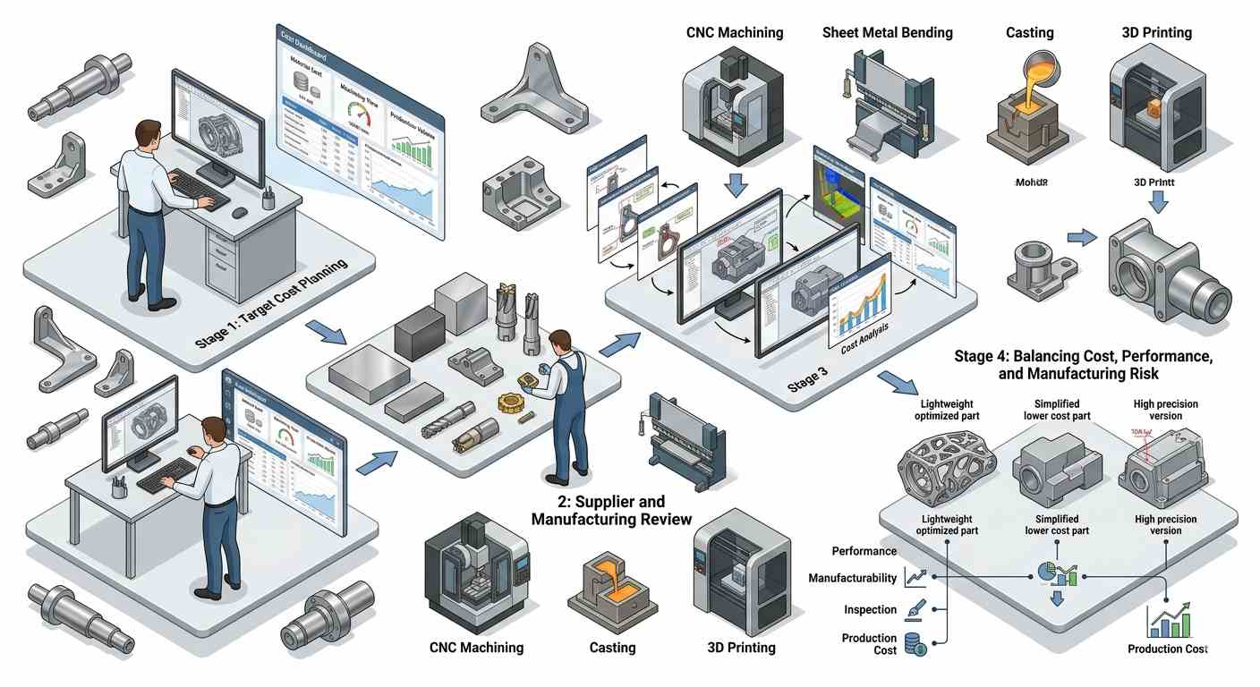
(AI generated) Isometric diagram showing the design to cost engineering workflow
Target Cost and Product Requirements
Design to cost engineering starts with a number. Before the first feature is drawn, the team establishes the target unit cost, which is what the part needs to cost in production to make the product viable at the intended price point and margin. That target cost becomes a constraint that every design decision is evaluated against, alongside the functional requirements.
Target cost needs to be realistic. A target cost based on wishful thinking rather than manufacturing knowledge produces a design that hits the cost target on paper and misses it in production. The most useful target costs are built from first-principles manufacturing analysis, estimated cycle time, material cost, setup frequency, inspection requirements, and overhead allocation, rather than reverse-engineered from a desired margin.
Early Supplier and Manufacturing Input
The design team knows what the part needs to do. The manufacturing team knows what it will cost to make it. Getting those two groups talking before the design is fixed produces better outcomes than presenting a complete drawing to manufacturing and asking for a cost estimate.
Early supplier input in design to cost engineering typically covers material recommendations, what the design needs versus what's available, and cost-effectiveness. Process selection, whether CNC machining, sheet metal, casting, or 3D printing, makes more sense for the geometry and volume. And geometry feedback, which features add high cost, and whether they can be modified without compromising function.
Iterative Design and Cost Review
Design for cost doesn't happen in one pass. The design evolves, features get added, geometry changes, tolerances get refined, and the cost needs to be re-evaluated at each significant change. A formal design cost analysis at each major design milestone catches cost growth before it compounds.
The review process asks the same questions at each stage:
- What's the most expensive operation in this design?
- Is that operation there because the part needs it or because it's convenient?
- Can the same function be achieved with simpler geometry?
- Can the same tolerance be achieved with a more standard process?
Iterative questioning during design produces cost reduction that reactive redesign after the quote never fully recovers.
Balancing Cost, Performance, and Risk
Every design for cost decision involves a trade-off. Simplifying a feature reduces cost but may reduce performance. Loosening a tolerance reduces inspection cost but may affect assembly behavior. Switching to a cheaper material reduces material cost but may increase machining cost or reduce part life.
The discipline in design to cost engineering is making these trade-offs explicitly and deliberately rather than implicitly through default choices. A designer who specifies ±0.025mm tolerances everywhere because that's what they've always done is making implicit cost trade-offs without realizing it. A designer practicing design for cost asks "what does this part actually need?" before specifying anything, and chooses the answer that meets the requirement at the lowest cost rather than the answer that's familiar.
Major Manufacturing Cost Drivers
Geometry Complexity and Machining Time
Machining time is the primary cost driver in CNC manufacturing. In practice, this shows up in several ways. More complex geometry increases tool paths, tool changes, setups, and total machine time. Machine time is a direct cost, whether the tool is cutting or simply repositioning. A part that takes 45 minutes to machine is typically far more expensive than one taking 15 minutes, assuming similar setup and material conditions.
Geometry complexity directly affects machining time. Multi-angle features often require extra setups or 5-axis motion. Deep pockets slow down cutting because tool rigidity becomes a constraint. Thin walls introduce deflection, which forces lighter passes. Small internal features usually require smaller tools and slower feeds. These effects compound into longer cycle time and higher cost.
Tolerance Requirements and Inspection Operations
Tight tolerances cost money in two places: machining and inspection.
| Area | Why Tight Tolerances Increase Cost |
|---|---|
| Machining | Requires slower feeds, lighter cuts, precision tooling, and more in-process measurement time |
| Inspection | Requires CMM inspection, special gauges, or 100% part verification instead of sample checks |
The cost of a tolerance is not linear. Going from ±0.25mm to ±0.10mm is achievable on standard CNC equipment with standard parameters, modest cost increase. Going from ±0.10mm to ±0.025mm often requires finish passes, in-process gauging, and tighter environmental control during measurement, significant cost increase. Going from ±0.025mm to ±0.005mm may require grinding, lapping, or specialized equipment, major cost increase. Each tighter tolerance step typically increases machining and inspection effort, sometimes disproportionately depending on feature geometry, access, and measurement method.
Material Machinability and Tool Wear
Material choice affects machining cost significantly. A 6061 aluminum part and a 316L stainless part of identical geometry don't cost the same to machine. Aluminum machines roughly 3-5x faster than stainless, wears tools far more slowly, and can be run at higher cutting speeds that reduce cycle time. The material cost difference is often smaller than the machining cost difference.
Machinability ratings vary depending on the reference material and standard.
- In common AISI B1112-based comparisons:
- 1212 free-machining steel is used as 100% baseline.
- 316 stainless is often reported in the 40–60% machinability range, depending on reference scale (commonly benchmarked against AISI 1212 steel).
- Titanium alloys are significantly lower, often below 40%.
These directly affect cycle time and tool consumption, which ultimately determines part cost.
Surface Finishing and Secondary Processes
Every secondary operation after machining adds cost, such as anodizing, powder coating, bead blasting, heat treatment, electropolishing, and thread inserts. Each one involves handling, setup, processing, inspection, and sometimes external vendor coordination. A part that requires machining, bead blast, anodize, and laser marking has four distinct operations, four quality checks, and four opportunities for something to go wrong.
Design cost analysis that accounts for secondary operations often finds that surface finish requirements drive high cost. An as-machined part with a reasonable surface finish might cost $50. The same part with bead blast and Type III hardcoat anodize might cost $85. If the anodize is there because the part needs it for corrosion resistance, that's a justified cost. If it's there because it looked nice in the rendering, it's a design cost decision that was never actually made.
How Geometry Affects CNC Machining Cost
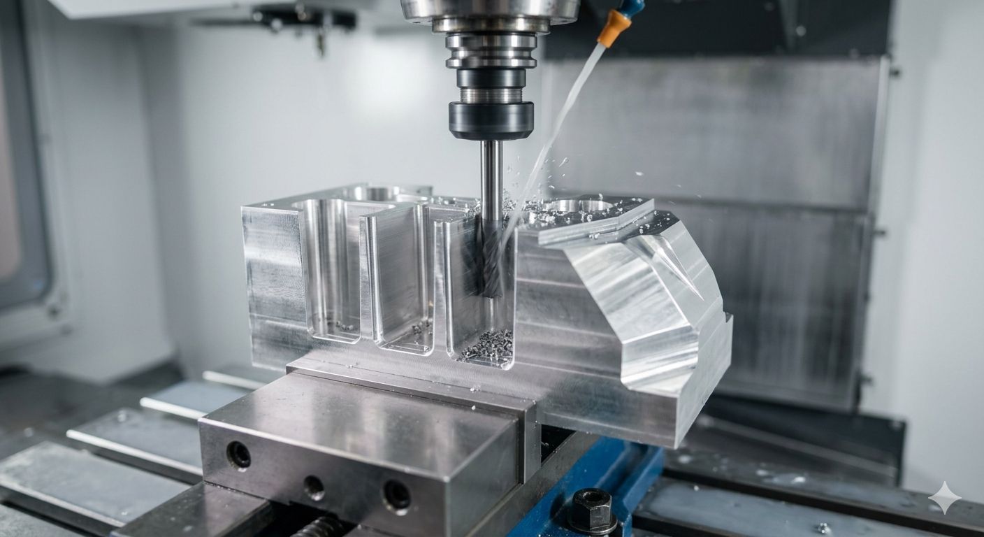
(AI generated) CNC milling machine machining a complex aluminum part
Deep Cavities, Thin Walls, and Tool Deflection
Deep cavities require long tools. Long tools deflect under cutting forces. Deflection causes inaccuracy, which means slower feeds to control it, which means more machining time. A 30mm deep pocket machined with a 6mm end mill at a 5:1 length-to-diameter ratio needs to be taken in slow, light passes to maintain dimensional accuracy. The same feature design at 15mm depth machines in roughly half the time.
Thin walls create a different problem. The wall deflects away from the tool during cutting, producing taper and dimensional error. The fix, light passes from both sides, working down in small increments, multiplies the number of passes dramatically. A 2mm wall on an aluminum part needs 4-6 rough passes, whereas a 5mm wall needs 1-2. The cost difference is real and significant.
Small Internal Radii and Toolpath Limitations
Internal corners in pockets and slots have a radius equal to the tool radius, always. A 4mm end mill produces 2mm internal radii. Producing 0.5mm internal radii requires a 1mm end mill, which runs much more slowly, deflects significantly, breaks more easily, and requires more passes to complete the feature. Specifying smaller internal radii than the machining operation requires dramatically increases the cost without a functional benefit in most cases.
The cost-effective rule: specify the largest internal radius that the part function allows. For most mechanical parts, 2-3mm internal radii are achievable at reasonable cost. Radii below 1mm require specialist tooling and slow operations. Sharp internal corners are not achievable with standard milling. They typically require EDM or grinding, which are significantly more expensive than milling.
Multi-Sided Features and Additional Setups
Each additional setup introduces non-productive time for fixturing, alignment, and verification, which becomes a meaningful cost driver, especially in low batch sizes. A part that requires three setups usually costs significantly more, depending on batch size and fixturing complexity. Features that only exist to add aesthetic complexity, chamfers at compound angles, features on multiple non-parallel faces, logos machined on back surfaces, often add one or more setups without functional justification.
The design for cost question for any feature is: which face does this live on, and does putting it there add a setup? If the answer is yes, there needs to be a functional reason that justifies the setup cost. If the reason is cosmetic or arbitrary, the feature should move to a face that's accessible in an existing setup.
Part Orientation and Workholding Constraints
Some geometries are simply hard to hold. A part with no parallel faces, no flat surfaces, and no obvious clamping points requires custom fixturing, which costs time to design, build, and set up. A part that was designed with flat clamping surfaces, consistent reference datums, and standard workholding compatibility in mind can be set up quickly with standard equipment.
Workholding difficulty shows up in quotes as setup cost, fixturing cost, or extended lead time. Design that considers how the part will be held in the machine, and creates features that support standard workholding, reduces the cost without affecting function.
Design Strategies for Lower Manufacturing Cost
Simplifying Features for Easier Machining
The most effective cost reduction strategy in design for cost is feature simplification, not removing features the part needs, but eliminating complexity that was added for non-functional reasons or out of design habit.
Common simplification opportunities: replacing complex freeform surfaces with simple planar or cylindrical geometry where function allows. Replacing narrow deep slots with wider shallower slots that use standard tooling. Replacing compound-angle chamfers with simple 45° chamfers. Replacing organic blend radii with standard radius values that match available tooling. None of these changes what the part does. All of them reduce machining time.
Applying Tight Tolerances Only Where Necessary
A drawing with ±0.025mm on every feature costs more to produce than the same drawing with ±0.25mm on non-critical features and ±0.025mm only on the features that need it. Every tight tolerance on the drawing requires the machinist to measure it and the inspector to verify it. Unnecessary tight tolerances produce unnecessary cost without improving part performance.
The design for cost tolerance review asks for each tolerance: what happens if this feature is at the loose end of the tolerance? If the answer is "nothing significant," the tolerance is too tight. Functional tolerances, bearing fits, mating faces, and critical interfaces deserve tight specification. Cosmetic tolerances, non-mating surfaces, and reference geometry deserve standard machining tolerances.
Designing Around Standard Tooling and Stock Materials
Non-standard tooling costs money and adds lead time. A pocket radius that matches a standard end mill size, 3mm, 4mm, 5mm, 6mm, is machined with an off-the-shelf tool at standard cost. A pocket radius of 3.7mm requires a special tool, costs more per tool, and may increase lead time. The functional difference between 3.7mm and 4mm internal radii is zero in most applications. The cost difference is real.
The same logic applies to material selection. Standard stock sizes in common alloys, 6061-T6 aluminum round bar at 25mm, 38mm, and 50mm, are available immediately at standard pricing. Unusual alloys or non-standard sizes have higher material cost, minimum order quantities, and longer lead times. Designing around what's available rather than requiring what's unusual keeps the supply chain simple and the cost predictable.
Reducing Part Count and Assembly Complexity
Every part in an assembly is a cost center: material cost, machining cost, finishing cost, inspection cost, inventory cost, and assembly labor. Combining two parts into one, where the combined part can be manufactured efficiently, removes all of those costs for the eliminated part plus the assembly operation between them.
Design for manufacturability and cost analysis at the assembly level asks: which parts can be combined? Which fastened joints can become integrated features? Which separately machined components can become one machined part? The answer is often constrained by assembly sequence requirements, material differences, or serviceability, but asking the question during design produces cost reduction that redesigning at the production stage doesn't.
Material Selection and Manufacturing Trade-Offs
Machinability Differences Between Common Metals
Material machinability directly translates to cycle time and, therefore, part cost. Aluminum alloys machine at 3-5x the cutting speed of steel, producing proportionally shorter cycle times on equivalent geometry. The labor and machine cost per hour is the same. The part just finishes faster. On a complex 45-minute aluminum part, the equivalent stainless steel geometry might take 2.5-3 hours.
This math matters most for prototype and low-volume parts where machining labor is a large fraction of total part cost. At high volume with optimized tooling and automation, the machinability gap narrows but doesn't disappear. The design cost analysis for material selection needs to account for machining cost alongside material cost, a cheaper material that machines 4x slower may cost more per finished part than an expensive material that machines efficiently.
Balancing Mechanical Performance and Material Cost
Over-specifying material for the application is a common design for cost failure. A bracket that carries 200N of static load doesn't need 4340 alloy steel, 6061-T6 aluminum or mild steel is structurally more than adequate at significantly lower material and machining cost. A housing that sees no wear, no elevated temperature, and minimal load doesn't need 316L stainless, 6061 anodized aluminum does the same job at less than half the machined part cost.
The principle is using the material that meets the requirement, not the material that exceeds it most impressively. Over-specification is usually a risk management instinct, "if we use a stronger material, we can't be blamed if it fails", but it consistently produces parts that cost more than they need to without performing better in service.
Prototype Materials vs Production Materials
Prototypes don't always need to be made in the production material. For geometry validation and fit checking, a prototype in 6061 aluminum tells you whether the part assembles correctly even if production will be in 316L stainless. The stainless prototype costs 3x more and takes longer to machine for a test that doesn't require stainless properties.
The exception is when prototype testing needs to replicate production material behavior. Structural validation, fatigue testing, corrosion testing, and thermal testing all need production-equivalent material to produce data that applies to the production design. The design cost analysis question for prototype material is: what is this prototype testing, and does the test result depend on material properties?
Material Availability and Supply Considerations
Lead time is cost. A part that can't be started because the material is on a six-week lead time has carrying cost, schedule impact, and opportunity cost that don't appear in the material price. Common alloys in standard sizes, 6061, 7075, 1018, 4140, 304, 316L in round bar, plate, and tube, are available from stock at standard pricing. Exotic alloys and non-standard sizes have unpredictable availability and premium pricing.
For production volumes where material is ordered on a regular schedule, lead time is manageable. For prototype and low-volume work where material needs to be available quickly, designing around stock materials and standard sizes keeps the schedule predictable and the cost known in advance.
Design for Cost in Sheet Metal Fabrication
Bend Radius and Forming Constraints
Sheet metal forming cost is driven by how many operations it takes to produce the flat pattern and formed geometry. Bends at consistent radii, matching the tooling available, form cleanly and quickly. Non-standard bend radii require special tooling. Bends in unusual locations require repositioning between press brake operations. Each non-standard requirement adds setup time, which translates into cost.
The practical design for cost rule for sheet metal: specify bend radii equal to 1-1.5x material thickness (the minimum achievable with standard tooling), use consistent bend radii throughout the part, and orient bends so they're accessible from standard press brake positions. These aren't arbitrary constraints. They define the geometry that standard sheet metal equipment produces efficiently.
Reducing Welding and Secondary Assembly
Welding typically introduces higher labor and setup cost compared with formed features, particularly in low-volume fabrication. Every weld joint in a design is a cost item. Features that require welding because of assembly geometry could often be redesigned as formed features, a return flange, a bent tab, an embossed feature, that eliminate the weld without affecting function.
Design for cost in sheet metal asks: Is this weld there because forming can't produce the geometry, or because the designer didn't consider forming alternatives? The second category is where cost reduction lives. A four-sided box that's welded at all four corners could be a three-bend channel with one weld, or a complete formed enclosure with no weld at all, depending on the depth-to-width relationship.
Flat-Pattern Efficiency and Material Utilization
Sheet metal parts are cut from flat stock. The flat pattern efficiency determines how much of the purchased material ends up in the finished part. A part whose flat pattern nests efficiently in a standard sheet size wastes little material. A part with an odd shape that leaves large remnants wastes a significant fraction of the material cost.
Flat pattern efficiency is a design parameter that most designers don't think about because they're working in 3D, and the flat pattern is something the manufacturing software generates. But designing parts with nesting in mind, keeping overall dimensions within common sheet sizes, designing shapes that can be arrayed efficiently, and combining multiple parts in a single sheet layout can reduce material waste by 20-30% with no functional impact.
Hardware and Fastener Selection
PEM nuts, studs, standoffs, and similar press-in hardware are fast to install in a production environment when the tooling is already set up. Non-standard hardware, custom thread sizes, unusual materials, specialty fasteners, requires sourcing effort, often has minimum order quantities, and adds supply chain complexity. Standard hardware in stock sizes is available off the shelf, familiar to assemblers, and interchangeable with other designs.
Prototype Cost vs Production Cost
CNC Prototypes vs Production Tooling
CNC prototyping is often evaluated as part of a broader cost strategy rather than unit price. A machined prototype may be more expensive per piece than production tooling output, but it reduces the risk of committing to expensive tooling before geometry and function are validated. In most CNC workflows, this trade-off determines total program cost more than individual part pricing.
Prototype Optimization vs Production Optimization
Prototypes and production parts are optimized for different things. A CNC machined prototype is optimized for accuracy and design validation, it's machined from solid, often over-engineered relative to production intent, and finished to a standard that makes test data trustworthy. A production injection-molded or die-cast part is optimized for cost at volume, tooled for fast cycle times, and designed around the constraints of the production process.
The design to cost engineering challenge is ensuring that optimizations made for the production process are incorporated before tooling is committed, not discovered afterward. Wall thickness changes, draft angles, gate locations, and parting line positions all of these affect production cost and quality, and all of them need to be in the design before tooling, not after the first production sample.
When Higher Prototype Cost Is Justified
Structural testing that needs production-equivalent material. Regulatory submissions that need production-representative geometry. Customer demonstrations that need a production-quality appearance. Long-lead qualification testing that can't wait for tooled parts. These are applications where paying more for a more accurate, more representative prototype is genuinely justified by the risk reduction it provides.
The design cost analysis for prototype specification asks what the prototype is being used for and whether the additional cost of a higher specification produces proportional value. A prototype for internal fit checking doesn't justify 316L stainless with electropolish. A prototype for regulatory submission in a medical device program very likely does.
Transitioning From Prototype to Scalable Production
The transition from CNC prototype to production manufacturing is where design for cost decisions made during prototyping either pay off or create problems. A prototype design that was optimized for CNC machining without considering the production process, injection molding, die casting, or stamping needs to be redesigned before tooling. Features that are easy to machine are not always easy to mold, cast, or stamp.
Design to cost engineering during prototyping anticipates this transition. It asks, "If this goes to injection molding at volume, what changes?" and makes those changes before the prototype stage rather than after. The prototype may cost slightly more to produce this way, features designed for moldability rather than machining ease take more CNC time, but the production tooling cuts without surprises.
Cost Analysis During Product Development
Identifying Features That Increase Machining Cost
Feature-level cost analysis identifies which specific geometry decisions are driving the majority of the cost. In a typical machined part, a small number of features account for the majority of the cycle time, a deep pocket, a tight bore, a multi-axis surface, a critical shoulder that requires grinding. Identifying these features and evaluating whether they can be simplified, combined, or eliminated produces more cost reduction than optimizing the standard features that were already efficient.
The analysis doesn't require sophisticated cost modeling software. Walking through the machining operations feature by feature, what tool does this require, how long does it take, how many setups does it add, identifies the expensive features clearly enough for a design decision.
Estimating Cycle Time and Setup Complexity
Cycle time estimation during design is the core skill in design cost analysis. An engineer who can look at a feature and estimate "that's going to take about 20 minutes to machine" has the knowledge to make design decisions that control cost. An engineer who can't estimate machining time can't make informed cost trade-offs during design.
The estimation doesn't need to be precise. Knowing that a deep 5:1 length-to-diameter pocket will take 3-4x longer than a shallow 2:1 pocket of the same diameter is enough to make a design decision. Knowing that a 0.5mm internal radius requires a 1mm end mill running at 1/10 the feed rate of a 6mm end mill is enough to justify increasing that radius.
Iterative DFM Review During Prototype Development
DFM review at the prototype stage catches the geometric and tolerance problems that abstract analysis misses. The first prototype reveals which features were harder to machine than expected, which tolerances were difficult to hold, and which aspects of the design created setup complications. That information is available to improve the next prototype iteration, but only if the engineering team reviews it deliberately rather than just accepting the first prototype as "good enough."
Common Design Mistakes That Increase Manufacturing Cost
Overly Tight Tolerances
It's easier to add a tight tolerance than to justify removing one. The result is drawings where ±0.025mm appears on features that could be ±0.25mm without any functional consequence. Every unnecessary tight tolerance adds inspection time, slows machining, and increases the rejection rate for minor deviations that don't affect performance.
The correction is tolerance analysis, functional dimension analysis that traces each toleranced dimension to its functional requirement and specifies the tolerance based on what the function requires, not on what seems safe. This takes more time during design and produces cheaper, faster-to-manufacture parts in production.
Geometry That Adds Unnecessary Machining Time
Aesthetic chamfers at compound angles. Decorative pockets with no functional purpose. Complex surface blends that replace simple flat geometry. Fillets specified smaller than the tooling that will machine adjacent features. Each of these adds machining time without adding function. In aggregate, they can easily double the cycle time of a part that could have been simpler.
The discipline is questioning every feature: what does this feature do? If the answer is "it looks better," that's a legitimate answer for consumer products where appearance is a selling point. For industrial components, internal parts, and anything that doesn't face the end customer, appearance features that add machining cost deserve to be removed.
Cosmetic Features Without Functional Value
Logo embossing, part number engravings, chamfered edges on non-contact surfaces, polished finishes on hidden faces, these are common on product designs that originated in consumer electronics and migrated to industrial applications where nobody will ever see those surfaces. They add finishing operations, increase cycle time, and add cost that the end customer doesn't pay for because they never know it's there.
This isn't an argument against appearance. It's an argument for applying appearance investment where it's visible and valuable, and removing it from where it isn't.
Ignoring Manufacturing Constraints During Design
The most expensive design mistake is designing without manufacturing knowledge. A designer who doesn't know that 0.5mm internal radii require 1mm end mills will specify them freely. A designer who doesn't know that threading a blind hole to within 2mm of the bottom is extremely difficult will put it on the drawing without a second thought. A designer who doesn't know that anodizing adds ±5-15 µm per surface will specify tight tolerances on anodized features without realizing they've created a process conflict.
The solution is earlier and more frequent communication between design and manufacturing. Not as a formal review at the end of the design process, but as an ongoing conversation throughout. DFM input during design is cheaper than DFM correction during production, which is cheaper than discovering the problem in the field.
Conclusion About Design for Cost
Cost is usually already decided while the part is still in CAD. Once it reaches machining, most of the choices that matter have already been made. At that point, changes tend to affect the schedule more than the outcome.
In practice, a small detail in the model can push machining time up without being obvious at the design stage. Sometimes it’s a pocket that needs more tool engagement than expected. Sometimes it’s a feature that forces extra setup. These things don’t stand out individually, but they add up once the part is being planned for production.
This is why drawings get reviewed before anything is cut. At JLCCNC, uploaded files are checked during quoting, not after. Geometry, tolerances, and material selection are looked at together in the context of how the part will actually be machined. The result is a quote, plus notes on where manufacturing effort is coming from.
Upload your CAD file to get a quote and engineering review from JLCCNC, including manufacturability feedback and cost drivers.
Precision CNC Machining Service
Professional manufacturing, fast turnaround, and quality assurance.
FAQ About Design for Cost in Manufacturing
Q: How does design for cost work in manufacturing decisions?
Design for cost is the process of engineering parts and assemblies to meet functional requirements while minimizing manufacturing, material, and production costs.
Q: What is the difference between design for cost and design to cost?
Design for cost improves manufacturability to lower cost, while design to cost starts with a fixed target cost and designs the product around it.
Q: How does geometry affect CNC machining cost?
Complex geometry increases machining time, tool changes, setup difficulty, and fixturing requirements, all of which raise CNC production cost.
Q: Why do tight tolerances increase manufacturing cost?
Tighter tolerances require slower machining speeds, more inspection, higher precision tooling, and sometimes secondary finishing operations.
Q: How does DFM help reduce production cost?
Design for manufacturability reduces unnecessary complexity, improves machining efficiency, lowers scrap risk, and shortens production time.
Q: When should manufacturing cost optimization begin?
Manufacturing cost optimization should begin during the early design stage before geometry, materials, and tolerances are finalized.
Keep Learning
Circularity GD&T Explained
Key Takeaways Circularity controls how round each cross-section is on a cylindrical, conical, or spherical surface. Each cross-section is checked separately. Circularity doesn't control taper, axis straightness, or alignment between sections. No datum is needed because circularity controls the shape of the feature itself. The circularity tolerance zone is bounded by two concentric circles whose radial separation equals the specified tolerance. Each circular element must fit within its own zone, evalua......
Press Fit Tolerance: Interference, Charts & Design Guide
Key Takeaways A press fit is an interference fit: the shaft is larger than the hole, and elastic deformation of the mating parts after assembly creates contact pressure that generates the friction holding the joint together. Press fit interference is the difference between the shaft diameter and the hole diameter. Minimum interference uses worst-case dimensions for the smallest overlap. Maximum interference uses worst-case dimensions for the largest overlap. Press fit tolerance is selected based on re......
GD&T Datum: Definition, Types, Symbols, and Datum Reference Frame
Key Takeaways A datum in GD&T is a theoretically exact reference used to locate or orient other features on a part. It is not the physical surface itself. A datum feature is the physical feature identified on the part and used to establish a datum. The datum itself is the theoretically exact geometric reference derived from that feature. Datums become especially important when several features have to work together. A hole pattern, bearing bore, mounting face, or mating surface may need to establish t......
GD&T Runout: Definition, Symbol, Measurement & Tolerance
Key Takeaways Runout limits surface variation while a part rotates around its specified datum axis. The datum feature establishes the axis used for the runout requirement. You compare the full indicator variation during rotation with the tolerance stated on the drawing. Circular runout applies at individual circular sections of the controlled surface. Total runout evaluates the controlled surface across its specified extent. Runout is not a size tolerance, and its value is not determined by the diamet......
GD&T Perpendicularity: Definition, Tolerance & Examples
Key Takeaways Perpendicularity is an orientation control used for a feature specified at 90° to a datum. A surface callout controls the complete surface within two parallel planes set perpendicular to the referenced datum. An axis callout controls the derived axis inside the specified tolerance zone instead of controlling the physical surface directly. Perpendicularity does not establish the location of a feature. A drawing can require another geometric control when position also needs definition. Dat......
Concentricity in GD&T: Definition, Symbol, Tolerance, and Measurement
Key Takeaways Concentricity in legacy ASME GD&T controls the derived median points of a feature relative to a datum axis. It does not simply compare the axes of two fitted cylinders. Check the drawing standard first. Legacy ASME concentricity and ISO concentricity or coaxiality should not be interpreted as equivalent requirements. For the cylindrical example in this guide, the tolerance zone is a cylinder centered on the datum axis. The derived median points of the controlled feature must lie within t......