What Is Angularity GD&T? Symbol, Tolerance, and Examples
18 min
- What Is Angularity GD&T?
- Angularity Symbol
- Angularity Tolerance
- Angularity GD&T Example
- How Is Angularity Measured?
- Angularity Applications in CNC Machining
- Angularity vs Perpendicularity
- Common Mistakes When Applying Angularity GD&T
- FAQs About Angularity GD&T
Key Takeaway
- Angularity GD&T controls the orientation of angled surfaces and axes relative to a datum. It uses a basic angle and tolerance zone to define acceptable deviation.
- The angularity symbol is a parallelogram shape, always accompanied by a datum reference in the feature control frame.
- Angularity tolerance defines a zone, two parallel planes or a cylindrical zone for axis control, within which the entire controlled surface or axis must fall.
- Unlike straightness GD&T or flatness GD&T, angularity GD&T always requires a datum because it controls orientation relative to something else, not form in isolation.
- Angularity vs perpendicularity is a common confusion, perpendicularity is actually a special case of angularity at exactly 90 degrees, with its own dedicated symbol.
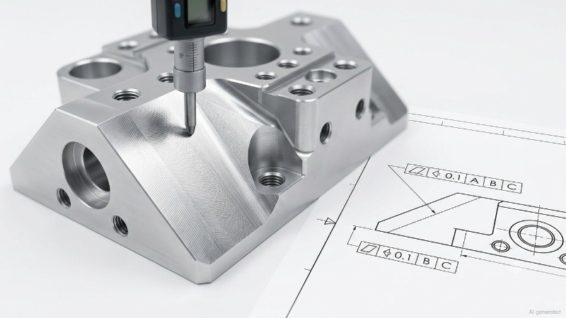
45-degree machined angled face
Most geometric dimensioning and tolerances control where a feature is or how flat or round it is. Angularity GD&T controls something different: how accurately a surface or axis is oriented at a specified angle relative to a datum.
It does not apply to 90 degrees, which has its own control (perpendicularity), or 0 degrees (parallelism). For any other angle, such as 30 degrees, 45 degrees, or 60 degrees, angularity tolerance controls whether the feature remains within the intended orientation.
Miss an angularity tolerance on a machined assembly and the consequences are usually immediate. Mating faces that should contact flush don't. Holes that should align with adjacent components don't. Angled slots that should guide parts through an assembly become interference points instead.
What Is Angularity GD&T?
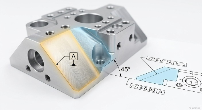
Angled surface with Datum A reference
Angularity Definition
Angularity GD&T is an orientation tolerance that controls how accurately a surface, axis, or center plane is oriented at a specified angle, other than 90 degrees, relative to a datum reference. It quantifies the deviation of the controlled feature from the theoretically exact angle defined on the engineering drawing.
The theoretically exact angle in an angularity GD&T callout is specified as a basic dimension, a value in a box on the drawing that carries no tolerance of its own. The angularity tolerance zone, defined in the feature control frame, controls how much the actual feature can deviate from that perfect theoretical angle.
Angularity GD&T belongs to the orientation tolerance category of GD&T controls, alongside parallelism (0 degrees) and perpendicularity (90 degrees). When the angle is exactly 90 degrees, perpendicularity is the correct control. When the angle is exactly 0 degrees (parallel), parallelism is the correct control. Angularity tolerance applies to all other angles.
Why Angularity Matters in Manufacturing
Angular features are common in machined components, chamfered seating surfaces, angled bosses, tapered bores, angled mating faces. Each of these features needs to be at the correct angle to function. A fixture seat face at the wrong angle mislocates the component in the fixture. A dovetail slot at the wrong angle creates an interference fit where a sliding fit was intended. A valve seat face at the wrong angle produces a seal that leaks.
GD&T angularity provides the engineering language to specify exactly how much angular deviation is acceptable. Without an angularity callout, the only angular control available is the general tolerance in the title block, which is usually expressed as a plus-or-minus degree tolerance that doesn't connect cleanly to the functional surface or axis behavior that the design actually requires. Angularity GD&T provides more precise, functionally meaningful control.
Angularity tolerances are only valuable if your manufacturing process can consistently achieve them. At JLCCNC, we produce precision CNC machined parts with tight GD&T requirements, including angular faces, angled bores, dovetail features, and complex multi-axis geometries. Whether you're building a prototype or moving into production, our engineering team reviews every design for manufacturability before machining begins.

Precision CNC Machining Service
Professional manufacturing, fast turnaround, and quality assurance.
Angularity Symbol
Angularity Symbol in GD&T
The angularity symbol is a parallelogram, a rectangle tilted at an angle, typically around 60 degrees from horizontal, that visually suggests an angled feature. It appears in the first compartment of the feature control frame, immediately identifying the callout as an angularity GD&T control.
The feature control frame for angularity always contains at minimum three elements:
[Angularity Symbol | Tolerance Value | Datum Reference]
Unlike form controls such as flatness or straightness, angularity GD&T always includes a datum reference. This is not optional; angularity tolerance is meaningless without a datum because it controls orientation relative to something else A feature control frame with the angularity symbol and no datum is an incomplete, technically incorrect callout.
For axis angularity, a diameter symbol (⌀) precedes the tolerance value in the second compartment, indicating a cylindrical tolerance zone rather than two parallel planes:
[Angularity Symbol | ⌀0.1 | Datum A]
Reading an Angularity Callout
A complete angularity GD&T callout on a drawing works as follows. A basic dimension, the theoretically exact angle, is boxed and associated with the angled feature. A leader line connects the feature control frame to the surface or axis being controlled. The feature control frame specifies the tolerance value and datum reference.
Reading the callout step by step:
- Find the basic angle (boxed dimension), this is the perfect angle the feature should be at
- Find the datum reference, this is what the angle is measured from
- Read the tolerance value, this is the width of the tolerance zone the feature must fall within
- Check for a diameter symbol, if present, the zone is cylindrical; if absent, it's two parallel planes
A callout reading: angularity symbol, 0.05, Datum A, on a surface with a boxed 45° dimension, means: the surface must be within a tolerance zone of two parallel planes 0.05mm apart, oriented at exactly 45 degrees to Datum A.
Common angularity mistakes include selecting the wrong datum, applying unnecessarily tight tolerances, and confusing linear tolerance zones with angular measurements.
Angularity Tolerance
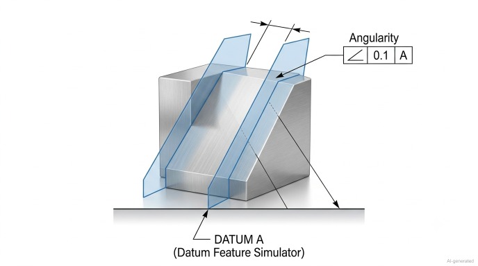
Angularity tolerance zone for surface
Surface Angularity Tolerance
Surface angularity tolerance defines a zone bounded by two parallel planes separated by the tolerance value, oriented at the theoretically exact angle relative to the datum. Every point on the controlled surface must lie between those two planes.
The tolerance zone floats; it can translate toward or away from the datum to best fit the actual surface What it can't do is rotate. The angular orientation of the two parallel planes is fixed at the basic angle specified on the drawing. The angularity tolerance controls only the orientation deviation, not the location of the surface.
This is an important distinction in GD&T angularity: the surface can be in the wrong position (too high, too low, too far) and still pass the angularity callout, as long as the surface is at the right angle within the tolerance zone. If position also matters, a profile tolerance or a combination of controls is needed.
Axis Angularity Tolerance
Axis angularity tolerance, applied to holes, pins, shafts, and cylindrical features, defines a cylindrical zone within which the derived axis of the feature must fall. The diameter of that cylinder equals the tolerance value preceded by the ⌀ symbol.
When controlling a drilled hole at an angle relative to a datum, axis angularity GD&T specifies a cylinder of diameter equal to the tolerance value, oriented at the basic angle relative to the datum. The actual axis of the hole, determined by the centers of cross-sections along the hole's length, must fall inside that cylinder.
Axis angularity tolerance allows the feature's center to deviate in all directions simultaneously within the cylindrical zone, which is more permissive than a two-plane zone for cylindrical features. This is why axis angularity tolerance is usually applied to cylindrical features (holes, pins) and surface angularity tolerance is usually applied to planar features (faces, slots, shoulders).
Angularity uses different tolerance zones depending on the controlled feature. Planar surfaces are controlled by two parallel planes, while cylindrical features use a cylindrical zone around the theoretical axis.
Angularity controls orientation rather than feature location. The tolerance zone can shift to contain the surface, but it cannot rotate away from the specified basic angle. Additional GD&T controls may be required when feature location must also be controlled.
Angularity GD&T Example
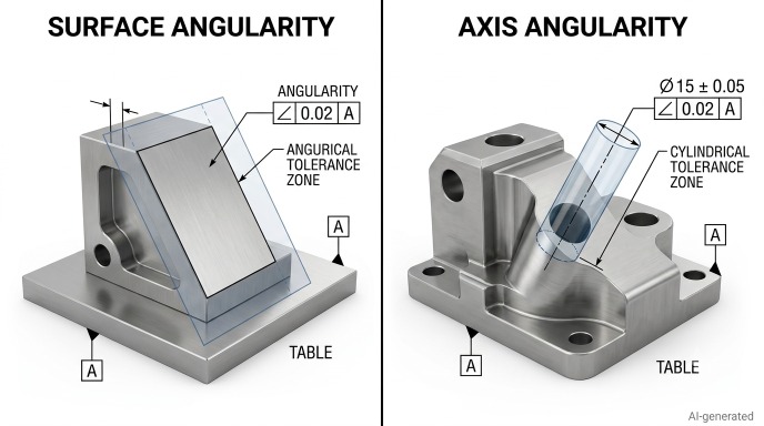
Surface vs axis angularity zones
Surface Angularity Example
Consider a machined aluminum block with an angled face that's supposed to be at 45 degrees to the base face (Datum A). The drawing shows a boxed 45° dimension between the angled face and Datum A, with a feature control frame containing: angularity symbol, 0.08, A.
What this angularity GD&T example means: the angled face must lie between two parallel planes 0.08mm apart, with those planes oriented at exactly 45 degrees to Datum A. The face can be at slightly different positions (higher or lower on the block) as long as it's within that 0.08mm angled zone.
At inspection, the part sits on Datum A (the base face, flat on the surface plate). The inspector or CMM probes multiple points across the angled face and evaluates whether all those points fall within the 0.08mm zone at 45 degrees. If the best-fit plane through the probed points deviates from the theoretically exact 45-degree plane by more than 0.08mm total, the part fails the angularity tolerance.
Hole or Axis Angularity Example
A hydraulic manifold block has a port drilled at 30 degrees to the main bore axis (Datum B). The feature control frame reads: angularity symbol, ⌀0.1, B. The basic dimension shows 30° relative to Datum B.
This angularity GD&T example for an axis means: the actual axis of the angled port must fall within a cylinder 0.1mm in diameter, oriented at exactly 30 degrees to Datum B. The CMM determines the actual axis by probing multiple cross-sections through the bore length, finding the center of each, and evaluating whether the line connecting those centers falls inside the ⌀0.1mm cylindrical zone.
If the drill wandered 0.06mm from the intended axis orientation (within the ⌀0.1mm zone), the port passes. If it wandered 0.12mm, it fails, and the hydraulic fitting that mates with this port may not align correctly with the intended flow path.
How Is Angularity Measured?
Coordinate Measuring Machine (CMM)
CMM inspection is the standard method for angularity GD&T verification on precision parts. The CMM probes multiple points across the controlled surface or feature, constructs the best-fit plane or axis through those points, and calculates the angular deviation from the theoretically exact basic angle relative to the datum reference.
For surface angularity tolerance, the CMM calculates the zone width needed to contain all probed points at the specified angle, and compares that to the tolerance value. For axis angularity tolerance, the CMM calculates the distance the actual axis deviates from the theoretically exact axis within the cylindrical zone.
CMM measurement of angularity GD&T provides traceable, documented results that manual methods can't easily produce. For first article inspection and any part where the angularity tolerance is ±0.05mm or tighter, CMM is the appropriate inspection method.
Manual Inspection Methods
Sine bars and sine plates provide controlled angular positioning for manual angularity inspection. A sine bar set to a calculated height produces a precise tilt angle, when the part is placed on the sine bar and the controlled surface is measured with a dial indicator across its length, the variation in indicator reading represents the angularity deviation.
Angle gauges (precision angle blocks) provide reference angles for comparison measurement. The part's angled surface is compared to a known reference angle using a dial indicator to determine the deviation.
For less critical angularity verification, such as tolerances of ±0.1 mm or looser, a digital protractor may provide adequate verification. The measured angle can then be converted into linear deviation based on the feature length.
Inspection Best Practices
Datum establishment before angularity measurement is critical. The part must be located against the datum reference, if Datum A is the base face, that face must be flat against a precision surface plate or CMM fixture before any angularity measurement is taken. Angular measurement from an incorrectly seated datum produces results that don't represent the actual angularity deviation.
Reliable angularity inspection depends on correct datum establishment, sufficient measurement points across the feature, and stable temperature conditions during measurement.
Temperature equilibration matters for tight angularity tolerances. A part that was machined warm and brought to the inspection room cold may measure differently than when at the standard 20°C reference temperature, particularly for large parts with significant thermal expansion coefficients.
Angularity Applications in CNC Machining
Maintaining Angular Features
Angular features on CNC machined parts, angled faces, compound chamfers, angled bores, dovetail slots, are produced through deliberate tool paths, part rotation, or fixture tilting rather than as byproducts of standard axis motion.
Angularity tolerance tighter than ±0.05mm (in the linear zone sense) typically requires active process management, verified fixture setup against a reference, first-article angularity inspection before the full run, and tooling selection appropriate for the required angular feature quality.
CNC Machining Considerations
Fixture setup is the primary angularity accuracy factor in CNC machining. A part clamped on an angled fixture that's 0.1 degrees off produces an angular feature that's 0.1 degrees off, no amount of CNC accuracy compensates for an inaccurate fixture. Verify fixture angles using precision angle gauges or CMM before the first production cut.
Tool path programming for angled features in 3-axis machining uses either a tilted workpiece in a fixed fixture or a compound tool path that produces the angle through coordinated axis motion. For 5-axis machining, the rotary axes tilt the tool or part to produce the angular feature directly. Angularity tolerance tighter than ±0.1mm in 3-axis work typically benefits from a 5-axis approach that reduces setup error contribution to the total angularity deviation.
Thermal drift during long production runs affects angular features differently than they affect feature position. A fixture that expands unevenly under machining heat produces angular variation between the first and last parts in a batch that first-article inspection alone won't catch. Periodic in-process angularity checks on a production run with tight angularity GD&T requirements maintain process control through the run.
Quality Control During Inspection
First-article angularity inspection before committing to a full production run is standard practice for parts with tight angularity tolerance. The first part verifies that the fixture setup, tool path, and machining parameters produce the intended angular features before the entire batch is committed to potentially incorrect angular geometry.
In-process gauging for angularity, angle gauges, sine bars, or on-machine CNC probing, maintains process control without removing parts from the fixture for CMM measurement after each piece. For production runs where angularity is a critical characteristic, on-machine probing that measures the angular feature and flags deviations before the part is moved from the fixture enables real-time correction rather than post-process rejection.
Angularity vs Perpendicularity
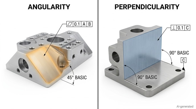
Angularity vs perpendicularity comparison
Key Differences
The relationship between angularity GD&T and perpendicularity is often misunderstood. Perpendicularity is not a separate geometric concept from angularity, it's angularity at exactly 90 degrees, with its own dedicated GD&T symbol because 90-degree features are so common in engineering that they merit a specific control.
| Factor | Angularity GD&T | Perpendicularity |
|---|---|---|
| Angle controlled | Any angle other than 0° or 90° | Exactly 90° |
| Symbol | Parallelogram (tilted rectangle) | Right angle symbol (L-shape) |
| Datum required | Yes, always | Yes, always |
| Tolerance zone | Two parallel planes or cylinder | Two parallel planes or cylinder |
| Basic dimension needed | Yes, basic angle | No, 90° is implied |
| Application | Angled faces, angled bores | Walls, flanges, perpendicular bores |
The tolerance zone for angularity GD&T and perpendicularity are geometrically identical, both use two parallel planes or a cylinder. The difference is only the angle of orientation: 90 degrees for perpendicularity, the specified basic angle for GD&T angularity.
When to Use Each Control
Use angularity GD&T when the feature angle relative to the datum is anything other than 0 or 90 degrees, 30°, 45°, 60°, compound angles, any non-right-angle requirement.
Use perpendicularity when the feature must be at exactly 90 degrees to the datum. The perpendicularity symbol is clearer and unambiguous for right-angle features, it immediately communicates the geometric intent to anyone reading the drawing without requiring them to find and check a basic dimension for the angle.
The practical consequence: substituting angularity GD&T for perpendicularity (by writing a 90° basic dimension with the angularity symbol) is technically correct but non-standard. Drawings that use the appropriate specific control, perpendicularity at 90 degrees, parallelism at 0 degrees, angularity at all other angles, are clearer and less prone to misinterpretation than drawings that use angularity for all orientation controls.
Common Mistakes When Applying Angularity GD&T
Incorrect Datum Selection
The datum for an angularity callout should be the feature that the angled surface or axis is functionally oriented relative to. Choosing a convenient datum, one that's easy to measure from, rather than the functional datum produces angularity GD&T that verifies the correct angle relative to the wrong reference, which may not guarantee correct assembly behavior.
For a machined angled face that must mate with a corresponding face in an assembly, the datum should be the primary mating surface of the part, not a secondary reference that's geometrically convenient for inspection.
Misunderstanding the Tolerance Zone
The tolerance zone for angularity GD&T is a linear distance, not an angular range. Engineers who interpret angularity tolerance as ±0.05 degrees rather than a 0.05mm wide zone over the feature length make errors in both specification and inspection.
The practical difference is significant. A 0.05mm angularity tolerance on a 100mm face means the face can deviate 0.05mm total across 100mm of length, which corresponds to an angular deviation of approximately 0.029 degrees. Specifying "±0.029 degrees" directly in an angular tolerance would be less clear than the GD&T angularity approach and harder to verify by linear measurement.
Over-Specifying Angularity
Applying tight angularity tolerance to features where angular precision doesn't affect function adds cost and inspection burden without improving the product. An angled chamfer for aesthetic purposes doesn't need the same angularity tolerance as an angled valve seat face that must seal against a mating component.
The general rule for angularity GD&T specification: use the loosest tolerance that the assembly function permits. Tight angularity tolerance requires slower machining, more precise fixtures, more rigorous inspection, and higher rejection risk. Reserve tight angularity GD&T for features where angular precision genuinely matters to the product's performance.
Complex angular features demand accurate machining, proper fixturing, and thorough inspection.
FAQs About Angularity GD&T
Q: What is angularity in GD&T?
Angularity GD&T is an orientation tolerance that controls how accurately a surface or axis is oriented at a specified angle, other than 0 or 90 degrees, relative to a datum reference. The angularity tolerance zone is defined by two parallel planes (for surfaces) or a cylinder (for axes) oriented at the theoretically exact basic angle specified on the drawing.
Q: What does the angularity symbol mean?
The angularity symbol in GD&T is a parallelogram shape, a tilted rectangle, that appears in the first compartment of the feature control frame. It identifies the callout as an angularity GD&T control. The angularity symbol always appears with a tolerance value and a datum reference in the feature control frame.
Q: How is angularity different from perpendicularity?
Perpendicularity is angularity at exactly 90 degrees, it's a special case of the same orientation concept with its own dedicated symbol. GD&T angularity controls features at any angle other than 0 degrees (parallelism) or 90 degrees (perpendicularity). The tolerance zones for both controls are geometrically identical, two parallel planes or a cylinder, differing only in orientation angle.
Q: How do you measure angularity?
CMM inspection is the standard method, the CMM probes the controlled surface or axis, constructs a best-fit plane or axis through the probed data, and evaluates the deviation from the theoretically exact angle relative to the datum. Manual methods include sine bars set to the exact angle with dial indicator verification, and angle gauges used as reference comparators. For tight angularity tolerances (below approximately ±0.05 mm), CMM inspection is often the preferred method because it provides higher measurement accuracy and traceability.
Q: What is angularity tolerance in machining?
Angularity tolerance defines how much an angled surface or axis can deviate from its theoretically exact angle relative to a datum. It helps ensure angled features fit and function correctly during assembly.
Keep Learning
Circularity GD&T Explained
Key Takeaways Circularity controls how round each cross-section is on a cylindrical, conical, or spherical surface. Each cross-section is checked separately. Circularity doesn't control taper, axis straightness, or alignment between sections. No datum is needed because circularity controls the shape of the feature itself. The circularity tolerance zone is bounded by two concentric circles whose radial separation equals the specified tolerance. Each circular element must fit within its own zone, evalua......
Press Fit Tolerance: Interference, Charts & Design Guide
Key Takeaways A press fit is an interference fit: the shaft is larger than the hole, and elastic deformation of the mating parts after assembly creates contact pressure that generates the friction holding the joint together. Press fit interference is the difference between the shaft diameter and the hole diameter. Minimum interference uses worst-case dimensions for the smallest overlap. Maximum interference uses worst-case dimensions for the largest overlap. Press fit tolerance is selected based on re......
GD&T Datum: Definition, Types, Symbols, and Datum Reference Frame
Key Takeaways A datum in GD&T is a theoretically exact reference used to locate or orient other features on a part. It is not the physical surface itself. A datum feature is the physical feature identified on the part and used to establish a datum. The datum itself is the theoretically exact geometric reference derived from that feature. Datums become especially important when several features have to work together. A hole pattern, bearing bore, mounting face, or mating surface may need to establish t......
GD&T Runout: Definition, Symbol, Measurement & Tolerance
Key Takeaways Runout limits surface variation while a part rotates around its specified datum axis. The datum feature establishes the axis used for the runout requirement. You compare the full indicator variation during rotation with the tolerance stated on the drawing. Circular runout applies at individual circular sections of the controlled surface. Total runout evaluates the controlled surface across its specified extent. Runout is not a size tolerance, and its value is not determined by the diamet......
GD&T Perpendicularity: Definition, Tolerance & Examples
Key Takeaways Perpendicularity is an orientation control used for a feature specified at 90° to a datum. A surface callout controls the complete surface within two parallel planes set perpendicular to the referenced datum. An axis callout controls the derived axis inside the specified tolerance zone instead of controlling the physical surface directly. Perpendicularity does not establish the location of a feature. A drawing can require another geometric control when position also needs definition. Dat......
Concentricity in GD&T: Definition, Symbol, Tolerance, and Measurement
Key Takeaways Concentricity in legacy ASME GD&T controls the derived median points of a feature relative to a datum axis. It does not simply compare the axes of two fitted cylinders. Check the drawing standard first. Legacy ASME concentricity and ISO concentricity or coaxiality should not be interpreted as equivalent requirements. For the cylindrical example in this guide, the tolerance zone is a cylinder centered on the datum axis. The derived median points of the controlled feature must lie within t......