GD&T Flatness: Flatness Tolerance and Symbols Explained
16 min
- What Is GD&T Flatness
- Flatness GD&T Symbol and Drawing Interpretation
- Flatness Tolerance in GD&T Standards
- Achieving Flatness in CNC Milling
- Measuring Flatness in Manufacturing
- Flatness GD&T vs Other Geometric Controls
- Importance of Flatness in CNC Manufacturing
- FAQ About GD&T Flatness
Key Takeaways
- GD&T flatness controls how much a surface can deviate from a perfect flat plane, independent of size tolerances and without referencing any datum.
- The flatness GD&T symbol is a simple parallelogram shape, appearing alone in the feature control frame with no datum letters.
- Flatness tolerance defines a 3D zone, two parallel planes, and every point on the surface must fall between them.
- Flatness in machining is affected by cutting forces, workholding, thermal expansion, and residual stress, not just the final finishing pass.
- Surface flatness GD&T matters most on sealing faces, mounting surfaces, and any interface where two parts need to sit flush against each other.
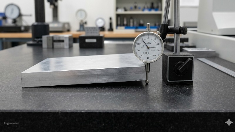
(AI generated) Machined metal plate flatness inspection on surface plate
You can test flatness by putting a part on a surface plate and rocking it gently. This is a qualitative check and does not replace GD&T-compliant measurement methods. If a part rocks on a surface plate, it is not flat—regardless of what its dimensional limits say. GD&T flatness is the geometric control designed to catch this exact issue, which standard size tolerances often fail to detect.
For a comprehensive look at other geometric symbols, review our GD&T in CNC machining guide.
This guide breaks down GD&T flatness in plain language, what the symbol means, how the tolerance zone actually works, and what it takes to hit tight flatness tolerances in real CNC machining.
What Is GD&T Flatness
Definition of GD&T Flatness
GD&T flatness is a form control that limits how much an entire surface can vary from a perfectly flat plane. It doesn't care where the surface is located, what angle it's at, or how big the part is, it only cares whether the surface itself is flat.
Flatness tolerance is how far apart those plates need to be to just barely fit the surface between them. If the surface can be contained between two parallel planes separated by 0.05mm, the flatness error is 0.05mm. Tolerance is explained this guide: Understanding CNC Machine Tolerances and Their Impact on Part Accuracy
Purpose of Flatness Tolerance
Size tolerances tell you how big something is. They don't tell you whether it's flat. A plate that's 10.00mm ± 0.05mm thick everywhere can still be bowed like a potato chip, every individual thickness measurement passes, but the surface itself is nowhere close to flat.
Flatness tolerance GD&T closes that gap. It's a separate check that doesn't care about thickness, length, or width, only about how much the surface itself wanders up and down across its area.
Why Flatness Matters in Manufacturing
Two parts that need to bolt together flush, seal against each other, or sit on top of one another all depend on flatness. A pump housing face that isn't flat leaks no matter how tight the bolts are torqued. A mounting plate that's bowed creates a gap that lets one corner lift when the opposite corner is clamped down, which then twists whatever gets bolted to it.
Flatness in machining isn't just a quality checkbox. A part that's out of flat changes how it behaves in an assembly in ways that are hard to diagnose after the fact, vibration, leaks, uneven wear, and stress concentrations that weren't in the design intent.
Flatness GD&T Symbol and Drawing Interpretation
GD&T Flatness Symbol Explained
The flatness GD&T symbol looks like a thin parallelogram, basically a flattened rectangle leaning slightly to the side. It sits in the first box of the feature control frame, followed by the tolerance value.
One thing that makes the flatness symbol easy to spot: like straightness, it never has a datum letter attached to it. Flatness is a form control, it evaluates the surface against itself, not against anything else. Flatness is a form control and does not use datums. If a datum reference is present in a flatness callout, it indicates a likely drawing error or misinterpretation of GD&T rules.
How to Read Flatness Callouts
Reading a flatness GD&T symbol callout is simpler than most people expect once you know what to look for.
Step one: find the symbol. Parallelogram shape, first box of the feature control frame.
Step two: read the number after it. That's the flatness tolerance, usually in millimeters. A callout reading [flatness symbol] 0.05 means the surface needs to fit within a 0.05mm flat zone.
Step three: check where the leader line points. Wherever it touches is the surface
When applied to a surface, flatness requires no datums or material condition modifiers. Flatness is a form control that does not use datums or material condition modifiers such as MMC or LMC. It always defines a fixed tolerance zone independent of feature size.
Flatness Tolerance Zone Concept
The tolerance zone for surface flatness GD&T is two parallel planes separated by the tolerance value. Picture two imaginary flat sheets of glass, perfectly parallel to each other, separated by exactly the tolerance distance, say 0.03mm. The entire controlled surface has to fit between those two sheets.
A common point of confusion is that these two imaginary boundary planes are not tethered to any reference datum; they are free to float. Flatness is evaluated by fitting two parallel planes that minimize the separation required to contain all measured points.
Flatness Tolerance in GD&T Standards
Flatness Tolerance Definition
In GD&T standards (ASME Y14.5), flatness tolerance is defined as the maximum permissible variation of a surface from a perfect plane, evaluated independently of any other feature, dimension, or datum on the part. It's one of the simplest geometric controls conceptually, which is part of why it's also one of the most commonly specified.
Tight vs Loose Flatness Tolerances
| Flatness Tolerance | Typical Application | Achievable By |
|---|---|---|
| 0.5mm or looser | Non-critical surfaces, cosmetic faces | Standard milling, as-cut |
| 0.1-0.25mm | General mounting surfaces, brackets | Standard CNC milling with finish pass |
| 0.025-0.1mm | Sealing surfaces, gasket faces | Fine milling, careful setup |
| 0.01-0.025mm | Precision mating surfaces, bearing faces | Surface grinding |
| 0.005-0.01mm | High-precision optical or metrology surfaces | Precision grinding, lapping |
| Below 0.005mm | Reference surfaces, gauge blocks | Lapping, optical flats |
The general rule for flatness in machining: the tighter the tolerance, the more the process needs to control thermal effects, workholding distortion, and residual stress, not just the cutting parameters of the final pass.
Engineering Drawing Requirements
A flatness GD&T callout needs three things to be unambiguous: the symbol itself, the tolerance value, and a clear leader pointing to the controlled surface. That's the complete specification, no datums, no modifiers required for a basic flatness control.
Where engineers sometimes add complexity unnecessarily: specifying flatness tolerance GD&T tighter than the function requires "to be safe." A mounting face for a bracket that bolts down with four screws and never needs to seal anything usually doesn't need 0.01mm flatness, 0.1mm is often plenty, and it's dramatically easier and cheaper to produce. Save the tight surface flatness GD&T callouts for surfaces that actually need them, seals, precision mating faces, optical references.
Achieving Flatness in CNC Milling
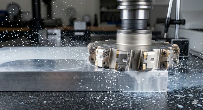
(AI generated) Face milling flat surface on aluminum block CNC setup
Flatness in CNC Milling
A face mill takes a flat pass across a surface and the result looks flat, but "looks flat" and "measures flat to 0.02mm" are different things. Flatness in CNC milling depends on the spindle running true, the table being flat, the tool path covering the surface with consistent overlap, and the workpiece not moving or flexing during the cut.
A single facing pass with a sharp face mill on a rigid setup typically produces flatness in the 0.05-0.15mm range over a few hundred millimeters. Getting tighter than that with milling alone usually means a finish pass at light depth of cut, slower feed, and a tool that's been checked for runout, small inconsistencies in any of these show up directly as flatness deviation.
Flatness in Grinding Processes
When flatness tolerance GD&T calls for something below what milling reliably achieves, say 0.01mm or tighter, grinding is usually the answer. Surface grinding achieves higher flatness because material is removed in controlled shallow passes with minimal cutting force and a geometrically stable reference motion.
Surface grinding for flatness works because each pass removes a tiny, consistent amount of material across the whole surface, there's very little force pushing the workpiece away from the wheel compared to milling. That's part of why ground surfaces reliably hit flatness numbers that milling struggles with.
Workholding and Fixturing Effects
It is common for a part to measure perfectly flat on a granite table, yet warp the moment it is clamped into a fixture. If clamping forces are uneven or compress a thin-walled section, the part deform during cutting. Once released, the material springs back, distorting the newly machined face.
For tight surface flatness GD&T requirements, this means checking that the part sits flat on the fixture before clamping (not just that it's held tightly), and that clamping force is distributed rather than concentrated at a few points that could bow a thin section.
Thermal and Residual Stress Considerations
A part that measures flat right off the machine, while it's still warm from cutting, can measure differently once it cools to room temperature. Uneven cooling, one area of the part cooling faster than another, pulls the surface slightly as the material contracts at different rates in different areas.
Residual stress from earlier operations does something similar. If a part was rough-machined aggressively on one side and then finished, the stress released by the rough machining can cause the part to bow slightly after the finish pass, even though the finish pass itself was perfectly executed. For tight flatness tolerance GD&T requirements, letting the part sit and stabilize between rough and finish operations, and measuring at a consistent temperature, avoids chasing a flatness number that's actually just thermal drift.
Process Capability and Flatness Control
Different processes have different realistic flatness capabilities, and matching the tolerance to the process avoids both underspecifying (parts that don't work) and overspecifying (parts that cost too much for no reason).
As a practical guide: standard 3-axis milling reliably holds 0.05-0.1mm flatness on parts up to a few hundred millimeters. With careful finishing passes, 0.02-0.05mm is achievable. Surface grinding extends that down to 0.005-0.02mm. Below 0.005mm typically needs lapping or specialized finishing. Knowing where your tolerance falls on this scale tells you immediately whether milling alone will do it, or whether a secondary process needs to be planned into the production sequence from the start.
At JLCCNC, we manufacture precision CNC parts with GD&T requirements down to demanding flatness, parallelism, and perpendicularity specifications. Whether you need machined prototypes or production quantities, our engineers review the part before machining to help avoid tolerance issues before they become expensive scrap.

Precision CNC Machining Service
Professional manufacturing, fast turnaround, and quality assurance.
Measuring Flatness in Manufacturing
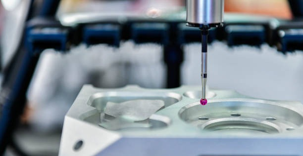
(Istock) CMM measurement
Surface Plate and Height Gauge Method
The simplest way to check flatness: put the part on a calibrated surface plate (a very flat reference surface) and use a height gauge or dial indicator to measure the surface at multiple points. The difference between the highest and lowest readings is the flatness deviation.
This method is quick, doesn't need expensive equipment beyond the surface plate itself, and works fine for looser flatness tolerance GD&T requirements, anything in the 0.05mm and up range. For tighter tolerances, the limitations of manual measurement (how many points you check, how precisely you can read the indicator) start to matter.
Coordinate Measuring Machine (CMM)
A CMM probes a grid of points across the surface and calculates the best-fit plane through all of them, then reports the maximum deviation of any point from that plane. This is the standard method for verifying surface flatness GD&T on precision parts because it's repeatable, documented, and not dependent on an inspector's technique the way manual methods are.
More probe points give a more complete picture of the surface, a CMM program that checks 9 points might miss a local dip that a 25-point program would catch. For critical flatness in machining, the inspection point density should reflect how much of the surface actually matters and how likely localized variation is for that process.
Laser and Optical Measurement Systems
For large surfaces, machine beds, large plates, structural components, laser flatness measurement systems scan the surface and build a complete map of deviation across the whole area, rather than sampling discrete points. This catches local high and low spots that point-based methods might miss between probe locations.
Optical flats, precisely flat glass references, are used for extremely tight flatness tolerance GD&T requirements, often below 0.001mm, where the part is compared directly against the optical flat using interference patterns. This is specialist territory, reserved for reference standards and optical components rather than typical production parts.
Flatness GD&T vs Other Geometric Controls
Flatness vs Straightness
Flatness controls an entire surface in 3D, while straightness controls individual line elements or an axis.
| Factor | Flatness | Straightness |
|---|---|---|
| What it controls | Whole surface (2D area) | Line elements or axis (1D) |
| Tolerance zone | Two parallel planes | Two parallel lines, or a cylinder for axis |
| Datum required | No | No |
For more on how straightness works and where it applies, see Straightness GD&T Symbol, Tolerance, and Examples.
Flatness vs Parallelism
Flatness checks if a surface is flat on its own, while parallelism checks if a surface is flat and parallel to another surface.
| Factor | Flatness | Parallelism |
|---|---|---|
| Datum required | No | Yes |
| What it answers | "Is this surface flat?" | "Is this surface flat and aligned with that other one?" |
| Relationship to flatness | Independent control | Often implies a flatness requirement on top |
Flatness vs Perpendicularity
Flatness controls a surface relative to itself, while perpendicularity controls a surface's angle relative to a datum.
| Factor | Flatness | Perpendicularity |
|---|---|---|
| Datum required | No | Yes |
| What it answers | "Is this surface flat?" | "Is this surface at 90° to that datum?" |
| Can a flat surface fail this? | N/A | Yes, flat but tilted fails perpendicularity |
Importance of Flatness in CNC Manufacturing
Assembly Fit and Function
Two flat parts bolted together only sit flush if both surfaces are actually flat. If one has a slight bow, tightening the bolts either flexes the part to match (introducing stress that wasn't in the design) or leaves a gap at one area while the bolts clamp tight elsewhere. Either way, the assembly isn't behaving the way the designer assumed it would.
Sealing and Contact Surfaces
This is where surface flatness GD&T earns its keep most directly. A gasket can only compress so much, if the mating surface has a low spot bigger than the gasket can fill, that's a leak path. Flange faces, pump housings, valve bodies, anywhere two surfaces need to seal against each other or a gasket, flatness tolerance directly determines whether the seal actually seals.
Precision Engineering Requirements
For optical mounts, metrology fixtures, and reference surfaces, flatness in machining isn't about assembly at all, it's about the surface itself being a reliable reference. A fixture base that's supposed to provide a known flat reference for measuring other parts is only useful if it's actually flat to a tolerance tighter than whatever it's measuring.
Need a flatness-critical sealing surface, mounting plate, or precision mating component?
JLCCNC combines advanced CNC machining, precision inspection, and GD&T-focused manufacturing to help ensure your parts meet functional requirements, not just dimensional ones. From prototypes to production runs, we deliver accurate parts with fast lead times and transparent pricing.
Precision CNC Machining Service
Professional manufacturing, fast turnaround, and quality assurance.
FAQ About GD&T Flatness
Q: What is GD&T flatness?
GD&T flatness is a geometric tolerance that controls how much an entire surface can deviate from a perfectly flat plane, independent of the part's size dimensions and without referencing any datum.
Q: What is the flatness GD&T symbol?
A thin parallelogram shape, placed in the first compartment of the feature control frame, followed by the tolerance value. It never includes a datum reference letter.
Q: How is flatness tolerance defined?
Flatness tolerance defines a zone made of two parallel planes separated by the tolerance value. Every point on the controlled surface must fall between those two planes. The planes float to whatever orientation best fits the surface, they aren't fixed to any other feature.
Q: How is flatness measured in CNC machining?
Surface plate and height gauge or dial indicator for general tolerances. CMM with multi-point probing and best-fit plane calculation for precision tolerances. Laser scanning for large surfaces. Optical flats for the tightest reference-grade tolerances.
Q: What is the difference between flatness and surface finish?
Flatness is about the overall shape of the surface, is it bowed, wavy, or twisted across its area. Surface finish (Ra) is about the microscopic texture of the surface, how rough or smooth it feels at a much smaller scale. A surface can be perfectly flat with a rough finish, or smooth with poor flatness, they're independent characteristics.
Q: What flatness tolerance is achievable with CNC milling?
Standard 3-axis CNC milling reliably achieves 0.05-0.1mm flatness on typical part sizes. With a careful finish pass, sharp tooling, and good workholding, 0.02-0.05mm is achievable. Tolerances tighter than 0.02mm generally require surface grinding or lapping as a secondary operation.
Popular Articles
• Cutting with Precision: A Comprehensive Guide to CNC Water Jet Technology
• CNC Coolant Explained: Types, Maintenance & Safety
• Rake Angle in Machining: Machinists’ Guide to Perfect Cuts
• What Steps Are Taken To Minimize Waste In CNC Machining Processes?
• How EDM Wire Cutting Works: Complete Guide to Precision CNC Wire Cutting
Keep Learning
Chatter in Machining: Causes, Effects, and How to Reduce It
CNC milling operation producing visible chatter marks on an aluminum workpiece Quick Chatter Diagnosis Checklist Symptom Most Likely Cause First Action High-pitched squeal Regenerative chatter Change spindle speed ±15% Chatter only in deep pockets Excessive tool overhang Shorten tool Chatter on thin walls Low workpiece rigidity Improve fixturing Chatter after tool replacement Runout / holder issue Check tool holder Chatter only during finishing DOC too small / rubbing Increase feed or adjust speed It ......
What Is Tool Offset in CNC? Types, Setup & Best Practices
CNC tool offset setup with measurement overlay Key Takeaways CNC offsets connect programmed intent with actual cutter position. Length data guides Z-axis depth control. Radius data protects part size during contour milling. Geometry values define the cutter's measured baseline. Wear values support fine correction during production. Verified data lowers scrap risk before full machining. Good offset habits protect tools, fixtures, and parts. In the context of CNC machining , tool offset is the quiet set......
Trochoidal Milling: Complete Guide to High-Efficiency CNC Machining
Key Takeaways Trochoidal milling combines circular cutter motion with continuous forward feed. The cutter normally engages 5 to 20% of its diameter instead of making a full-width cut. A smaller engagement angle limits force changes during slotting and pocket roughing. Low radial engagement often allows greater axial depths of cut than conventional slot milling. CAM software calculates the circular path automatically from the selected machining parameters. This strategy is widely applied to titanium, s......
What Is Die Casting? Process, Materials, and Applications
Key Takeaways Die casting is a metal casting process that forces molten metal into a reusable steel mold under high pressure, producing parts with tight tolerances and good surface finish at high volume. Aluminum die casting is the most common form by far, thanks to its combination of light weight, decent strength, and good corrosion resistance. The die casting process runs through mold preparation, injection, cooling, and ejection in a cycle that can repeat every few seconds to minutes depending on p......
First Angle vs Third Angle: Understanding Orthographic Projection Methods
Key Takeaways Orthographic projection is the system that lets a 3D part be represented through multiple 2D views, front, top, side, and so on. First angle projection and third angle projection are the two standard methods for arranging those views, and they place views in opposite positions relative to the object. First angle projection is the ISO standard used across most of Europe, India, China, Russia, and many other countries following ISO standards Third angle projection is the standard in the Un......
Micro EDM Machining: Capabilities, Materials, and Applications for Precision Components
Key Takeaways About Micro EDM Machining Only electrically conductive materials can be machined. Hole diameters can reach below 50 μm on specialized equipment. The process produces almost no mechanical cutting force, making it suitable for thin or delicate features. Surface integrity still requires attention because recast layers and heat-affected zones may remain after machining. Micro EDM is often combined with CNC machining, with milling producing the main geometry before EDM finishes critical micro......