Surface Grinding in CNC: Process, Machine Types, and Precision Control
19 min
- What Is Surface Grinding in CNC Machining
- How Surface Grinding Works
- Surface Grinding Process Step-by-Step
- Types of Surface Grinders
- When Should You Use Surface Grinding
- What Determines Surface Finish and Accuracy
- Surface Finish and Precision Capabilities
- Surface Grinding vs Milling and Other Finishing Methods
- Applications of Precision Surface Grinding
- Common Problems and How to Fix Them
- When Surface Grinding Becomes Expensive
- FAQs About Surface Grinding
Surface grinding is a CNC machining process used to produce flat surfaces with high accuracy and fine surface finish. It removes material with an abrasive grinding wheel rather than a cutting tool. For a broader overview of grinding methods and machine types, see JLCCNC’s guide to CNC grinding machines.
Key Takeaways About Surface Grinding
- Surface grinding is usually a correction step, not the main cutting process. It is used when milling gets the part close, but not close enough.
- The real reason to grind is often functional. A surface may need to sit flat, seal properly, or carry a load without uneven contact.
- In production, grinding quality is not decided by the machine name alone. Setup stability, wheel condition, and heat control often matter more than the nominal process plan.
- A part can meet size on paper and still perform poorly if the ground surface is unstable or thermally affected.
- Surface grinding becomes expensive when the margin for error gets tight. Thin parts, hard materials, and high flatness demands leave less room for a fast, forgiving process.
This article explains:
- How surface grinding works in CNC machining
- When grinding makes more sense than milling
- What controls flatness, surface finish, and process cost in production
What Is Surface Grinding in CNC Machining
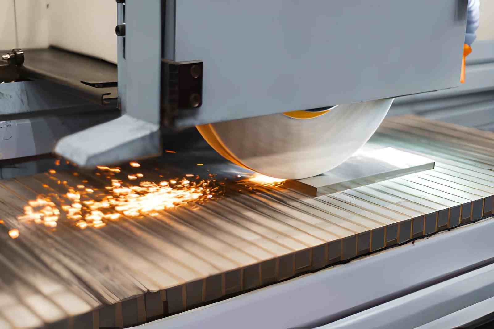
The image shows an industrial surface grinding machine machining a flat metal part. Sparks are visible as the grinding wheel removes material (iStock)
Surface grinding is a CNC finishing process that uses an abrasive wheel to remove small amounts of material and produce flat surfaces. Generally, it is applied in the final machining stages.
What Surface Grinding Actually Removes
Surface grinding removes material through abrasive interaction. Each grain acts like a small cutting point. As a result, material removal happens at a very fine scale:
- Removes microns of material per pass.
- Produces fine chips and grinding dust.
- Occurs through abrasive micro-cutting with localized friction.
- Suitable for hardened and soft metals.
Why Surface Grinding Is Used
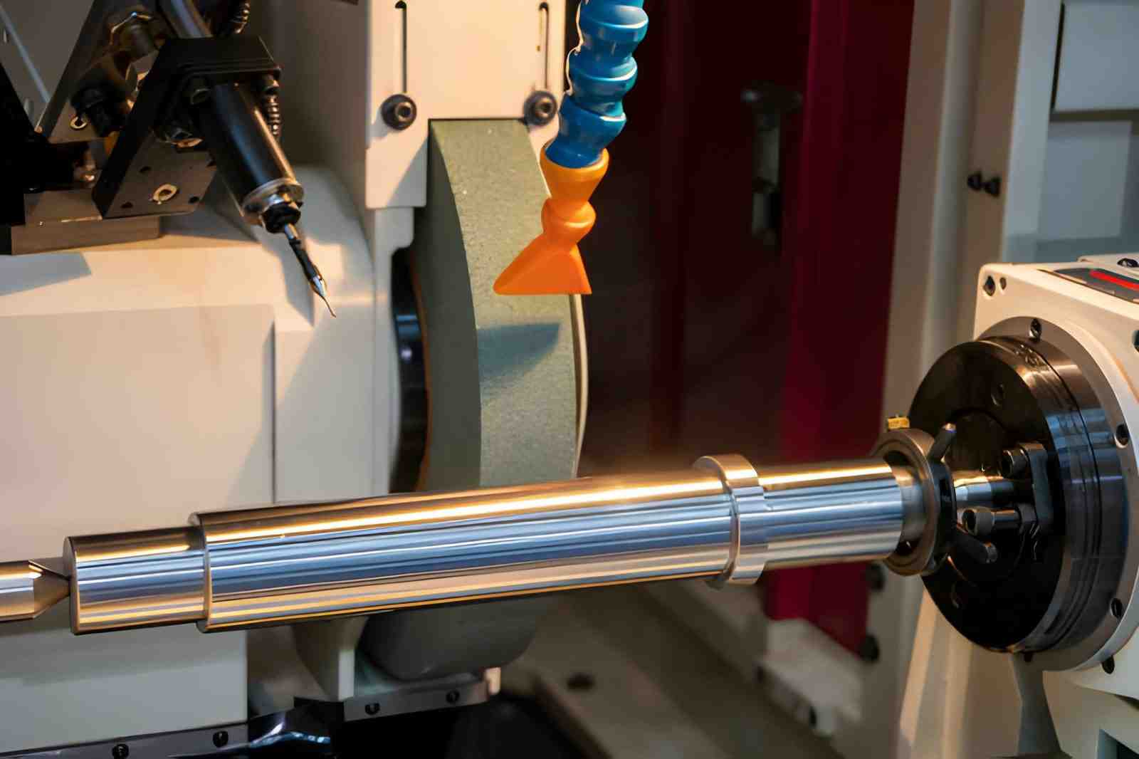
The image shows a CNC-controlled cylindrical grinding machine finishing a metal shaft (iStock)
- Surface grinding is used when milling cannot meet flatness or surface finish requirements under stable conditions.
- It improves flatness and surface finish under controlled conditions.
For example:
- It improves flatness, surface finish, and contact performance under controlled conditions.
- Produces low surface roughness values.
- Improves contact between mating parts.
- Corrects distortion after heat treatment.
How Surface Grinding Works
Surface grinding removes material through controlled interaction between the abrasive wheel and workpiece under continuous motion. Material removal happens at the micro scale through repeated contact events across the surface. Process stability depends on wheel speed, feed control, and grain condition.
Abrasive Grain Cutting vs Chip Formation
- Abrasive grain acts as an independent cutting edge that removes material through localized shear and micro-fracture.
- Material does not form continuous chips. Instead, it breaks into fine particles due to brittle and ductile interaction at the grain level.
- When grain edges dull, the process shifts toward rubbing.
Relative Motion Between Wheel and Workpiece
- The grinding wheel rotates at high surface speed (typically 25 - 35 m/s). This results in continuous abrasive contact at the grinding zone.
- The workpiece moves in a reciprocating table motion. This ensures progressive material removal across the full surface width.
- Cross-feed displacement shifts the contact path after each stroke. It helps prevent repetitive cutting lines and improves uniformity.
Spark-Out and Final Material Removal Behavior
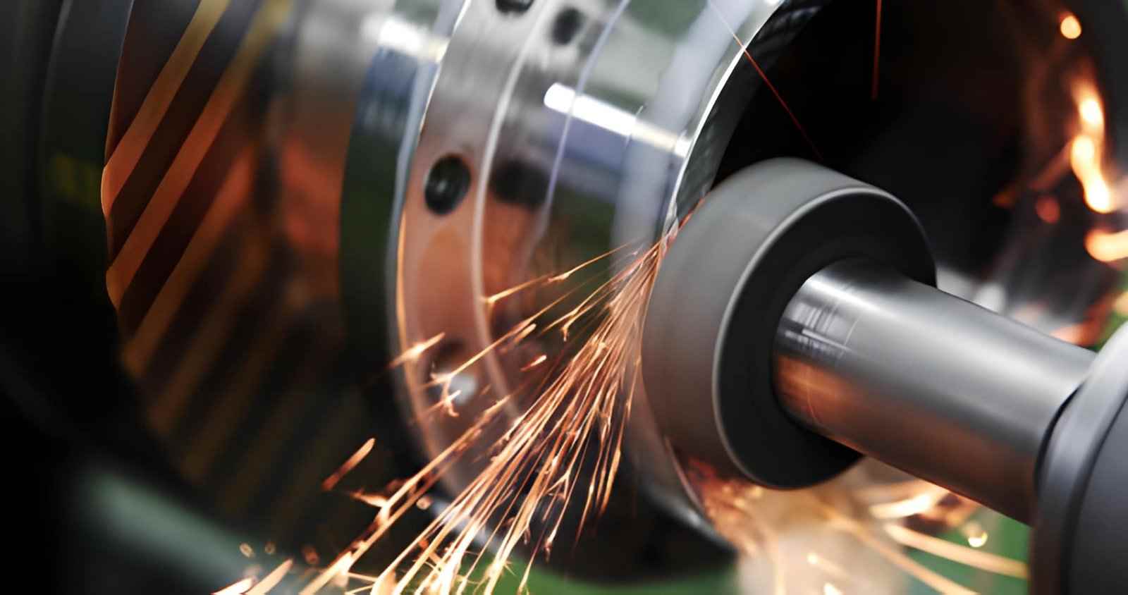
The image shows a high-precision grinding machine finishing a metal workpiece in a workshop (iStock)
- Spark-out maintains wheel contact without additional infeed, allowing residual material peaks to be removed.
- Elastic deformation from the machine structure and workpiece relaxes during this stage, improving geometric stability.
- Final surface quality stabilizes as the cutting force drops and only light abrasive interaction remains active.
Surface Grinding Process Step-by-Step
Once the material removal mechanism is understood, the next step is how the process is actually executed on the machine.
Surface grinding follows a controlled sequence to achieve flatness and surface quality. Each stage removes material under different load conditions and stability levels.
Machine Setup and Workpiece Alignment
Machine setup determines accuracy before any material removal begins.
Workholding is the first stability constraint. Most surface grinding relies on a magnetic chuck, typically providing holding force in the range of 80 to 120 N/cm² for ferrous parts. However, this does not guarantee uniform support. Thin or uneven parts can still deform under magnetic attraction or poor contact.
Even small misalignment leads to uneven flatness across the surface. If the part is not fully seated, local lifting occurs during grinding, which translates directly into flatness variation after release.
Technical Glance
- Magnetic chuck holding force: 80 to 120 N/cm² for steel components
- Pre-clamp flatness requirement: 0.02 to 0.05 mm maximum deviation
- Alignment check using dial indicator sweep within 0.01 mm tolerance
- Wheel runout control below 0.005 mm for precision grinding
Rough Grinding Passes
Rough grinding is used to remove unwanted material and prepare the surface for the final finish. In this operation, the cutting load remains higher, so high heat generation and wheel wear increase. To avoid this, the removal of material should remain within limits so that there are no burns or deformity.
Depth of cut:
0.01 to 0.05 mm (steel), up to 0.08 mm (cast iron).
Feed rate:
5 to 15 m/min, depending on wheel grit (46 - 60 grit range).
Wheel surface speed:
25 to 35 m/s for aluminum oxide wheels.
Coolant flow rate:
8 - 15 L/min for thermal stability.
Steel components may expand by 0.01 to 0.03 mm during roughing due to heat. That is why extra stock is always left for finishing correction.
Wheel Dressing Between Stages
Wheel condition changes quickly between roughing and finishing. As grains dull or load with material, cutting behavior shifts from shearing to rubbing.
In practice, dressing is not a separate step at the end. It is inserted between grinding stages to restore cutting sharpness and maintain consistent material removal.
Without proper dressing:
- Cutting force increases
- Surface finish degrades
- Thermal load rises unpredictably
Inconsistent dressing is one of the most common hidden causes of surface variation in production, especially when transitioning from rough to finishing passes.
Finishing and Spark-Out Process
Finishing pass defines the final geometry and surface condition. Spark-out is used to remove elastic deformation without additional infeed. This stage is sensitive to machine vibration and wheel sharpness.
| Parameter | Finishing Pass | Spark-Out Stage |
|---|---|---|
| Depth of Cut | 0.002 to 0.01 mm | 0 mm (no infeed) |
| Table Feed | 2 to 6 m/min | 0.5 - 1 m/min or dwell |
| Wheel Grit | 80 - 120 grit | Same wheel condition |
| Contact Load | Controlled light pressure | Residual elastic contact |
| Surface Finish | Ra 0.8 - 1.6 µm | Final stabilization effect |
Spark-out is important because it releases elastic stress from both the tool and the workpiece. It helps eliminate micro-waviness left from cutting pressure.
Inspection and Quality Check
- Flatness of granite plate measured with dial gauge ( 0.005 - 0.01 mm).
- Roughness of the surface using a profilometer (Ra 0.4 - 1.6 µm range).
- The parallelism between faces is sustained by a range of ±0.005 to 0.02 mm.
- Burn marks are typically checked using optical inspection at around 10× magnification.
For manufacturers, inspection results also indicate wheel wear and setup drift. Any deviation usually traces back to setup stability or thermal imbalance rather than cutting depth.
Types of Surface Grinders
The differences between surface grinding machines primarily lie in the way the spindle, table, and control system handle contact with the cutting. Machine type selection depends on desired accuracy, surface area, and production stability.
Horizontal vs Vertical Spindle Machines
Spindle orientation changes how the cutting force is applied to the workpiece surface. It also affects heat concentration and contact stability during grinding. The same orientation logic also appears in CNC milling, where spindle direction affects chip evacuation, setup strategy, and material removal behavior in different ways. For a broader machine-tool comparison, see JLCCNC’s guide to vertical vs horizontal CNC milling machines. Horizontal systems focus on precise control, while vertical systems increase surface engagement per pass.
| Parameter | Horizontal Spindle | Vertical Spindle |
|---|---|---|
| Contact Mode | Edge-line grinding contact | Full-face grinding contact |
| Force Direction | Lateral force across the surface | Downward distributed force |
| Heat Concentration | Localized at the contact line | Spread across a wider area |
| Accuracy Control | Higher for fine tolerances | Moderate for large surfaces |
- Horizontal spindle reduces contact area, improving flatness control on precision parts.
- Vertical spindle increases grinding coverage, improving efficiency on large surfaces.
- Horizontal setup minimizes thermal distortion due to lower contact area per pass.
Reciprocating Table vs Rotary Table Systems
Table motion defines how grinding contact is distributed across the surface. It affects cycle stability, thermal load, and surface uniformity. Reciprocating systems prioritize accuracy, while rotary systems prioritize continuous cutting efficiency.
| Parameter | Reciprocating Table | Rotary Table |
|---|---|---|
| Contact Pattern | Intermittent linear passes | Continuous circular contact |
| Thermal Load | Lower due to cooling intervals | Higher due to constant contact |
| Dimensional Control | High precision stability | Moderate consistency |
| Material Removal | Controlled and stepwise | Continuous and faster |
- Reciprocating motion reduces heat buildup by allowing cooling between strokes.
- Rotary motion improves productivity through uninterrupted grinding contact.
- Linear systems provide better dimensional stability for tight-tolerance parts.
CNC Surface Grinder vs Manual Machines
The control system determines repeatability and process stability in surface grinding. CNC machines automate feed, depth, and spark-out control, while manual machines depend on operator input. This directly affects consistency across multiple parts.
- CNC grinders maintain constant feed and depth, reducing variation between parts
- Manual machines rely on operator adjustment. So, this increases the risk of inconsistency.
- CNC control improves repeatability in finishing passes and spark-out cycles.
- Manual systems are better suited for low-volume or repair-based grinding work.
When Should You Use Surface Grinding
Here are the common situations when you can use surface grinding over other techniques.
When Flatness or Parallelism Cannot Be Achieved by Milling
CNC milling becomes difficult when machining long, slender, or thin surfaces. Tool pressure can bend the workpiece or deflect the cutter, leading to this effect. This tends to cause uneven height and slight angular errors across the face.
- Flatness drift appears on large plates after face milling.
- Thin sections distort under clamping and cutting load.
- Tool deflection creates a gradual taper across long surfaces.
When Surface Finish Requirements Go Beyond Cutting Processes
Cutting tools leave periodic tool marks due to chip formation and feed movement. These patterns become critical when surfaces require sealing, sliding, or precision contact.
- Milling marks typically range from 1.6 to 6.3 µm Ra.
- Grinding reduces peak roughness through abrasive micro-removal.
- Surface peaks are flattened instead of being cut in steps.
When Machining Hardened Materials or Final Surfaces
After heat treatment, the material's hardness changes, cutting behavior is significantly different. Milling becomes unstable due to tool wear and heat generation, while grinding maintains controlled removal.
- Hardened steels above 50 HRC reduce carbide tool efficiency.
- Post-heat-treatment distortion requires corrective machining.
- Grinding maintains dimensional control without heavy cutting force.
This is commonly applied to molds, dies, and high-load mechanical parts where the final surface condition cannot be left to conventional machining.
What Determines Surface Finish and Accuracy
Surface finish and accuracy in surface grinding depend on how mechanical cutting conditions, abrasive behavior, and heat generation interact during contact.
Each parameter affects material removal at the micro scale. Even a small instability in any factor reflects directly on:
- Surface flatness
- Waviness
- Surface roughness
Wheel Speed, Feed Rate, and Depth of Cut Interaction
- Wheel speed typically ranges from 25 to 35 m/s, where higher speed reduces chip thickness but increases friction heat at the grinding zone.
- Surface pattern density is determined by feed rate (2 - 10 m/min), with higher feed resulting in higher Ra values (above 1.6 - 3.2 µm) in steel.
- Cut depth above 0.02 mm leads to elastic deflection in the wheel and workpiece. This results in quantifiable drift of flatness of long surfaces of up to 0.01 mm.
Abrasive Type, Grain Size, and Bond Selection
- Aluminum oxide wheels are used for steels above 40 HRC. Silicon carbide is preferred for non-ferrous alloys due to lower adhesion.
- Grain size 80 - 120 produces finishing surfaces around Ra 0.8 - 1.6 µm. In comparison, while 46 - 60 grit supports faster stock removal with a rougher finish.
- Vitrified bonds provide stable shape retention for grinding operations, while resin bonds minimize cutting force for heat-sensitive materials.
Thermal Effects and Coolant Stability
- Local contact temperature at the grinding zone can exceed 600–900°C momentarily, which causes thermal expansion of 0.01 - 0.03 mm in steel components during cutting.
- Coolant flow around 8 - 15 L/min is required to maintain stable temperature and prevent surface burn or phase change in hardened steels.
Surface Finish and Precision Capabilities
Surface finish and precision capability define how smoothly a machined surface is produced and how tightly dimensions can be controlled.
Typical Surface Roughness Range (Ra)
- Standard production grinding achieves Ra 0.8 - 1.6 µm using 80 - 120 grit wheels under stable conditions.
- Fine finishing setups with controlled feed and dressing can reach Ra 0.2 - 0.8 µm on steel surfaces.
Achievable Flatness and Parallelism
- Flatness in stable setups typically stays within 0.005 - 0.01 mm for precision-ground plates and tooling surfaces.
- Parallelism between opposing faces is commonly controlled within 0.005 - 0.02 mm, depending on part size.
Realistic Tolerance Limits in Production
- Standard CNC surface grinding maintains dimensional tolerance around ±0.01 mm under normal shop conditions.
- High-precision grinding with stable thermal control can reach tighter limits near ±0.002–0.005 mm on small components.
Surface Grinding vs Milling and Other Finishing Methods
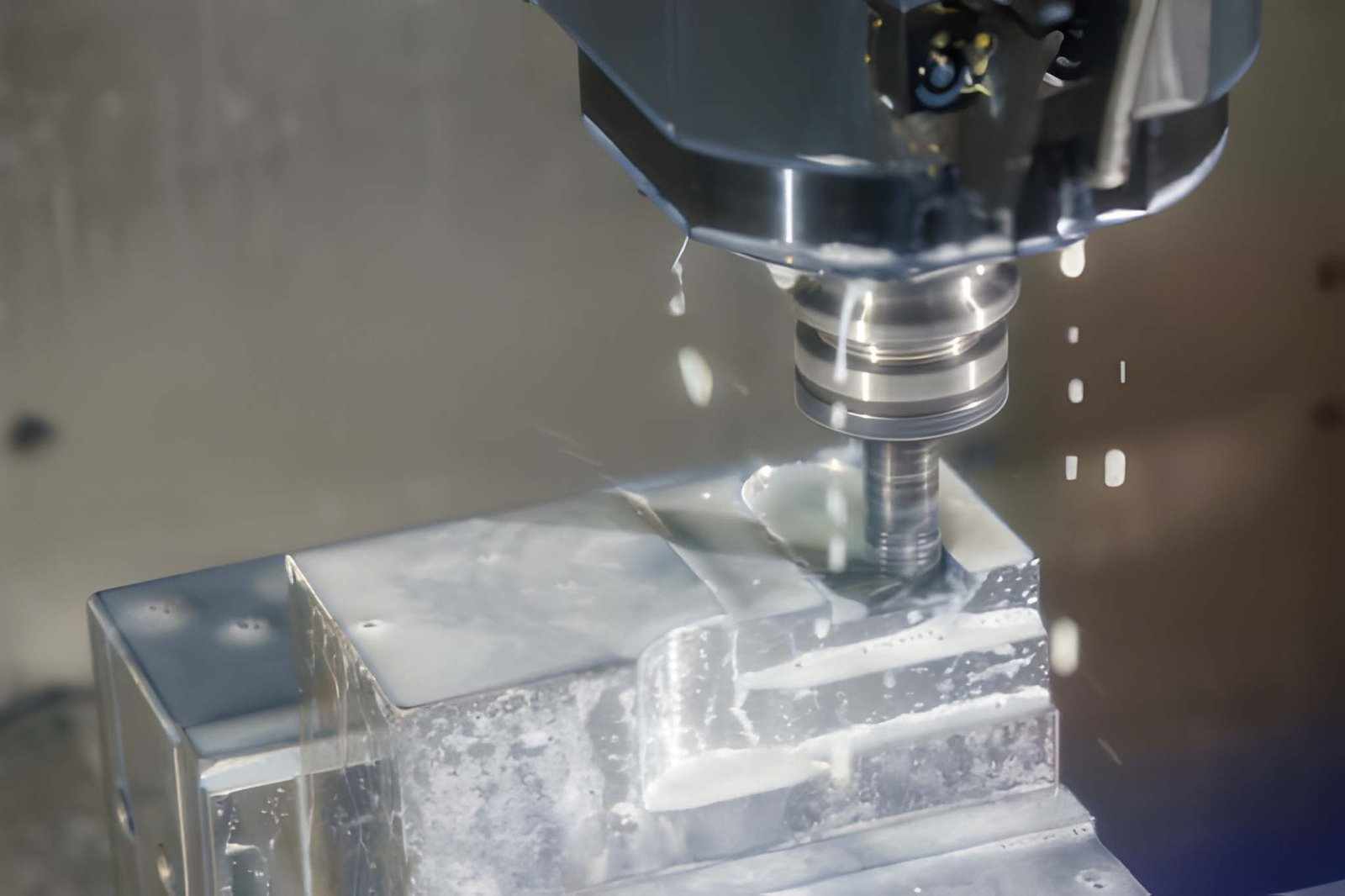
The image shows a CNC milling machine rough-cutting mold parts using liquid coolant (iStock)
Surface grinding, milling, and other finishing processes remove material using different cutting mechanisms. The main differences come from contact type, cutting force control, and thermal behavior.
Comparison of Finishing Processes
| Parameter | Surface Grinding | Milling (Finishing) | Honing | Lapping |
|---|---|---|---|---|
| Cutting Mechanism | Abrasive micro-cutting | Shear cutting with a rotating tool | Fine abrasive sliding motion | Free abrasive slurry action |
| Contact Type | Point/line contact | Edge or face contact | Full surface contact | Full surface contact under light pressure |
| Typical Ra Range | 0.2 - 1.6 µm | 1.6 - 6.3 µm | 0.1 - 0.4 µm | 0.01 - 0.2 µm |
| Flatness Control | High (0.005 - 0.01 mm) | Medium (0.02 - 0.1 mm) | High (internal surfaces) | Very high (ultra precision) |
| Material Removal Rate | Very low | Moderate to high | Very low | Extremely low |
| Thermal Impact | Moderate to high | Moderate | Low | Very low |
| Best Feature Type | Flat external surfaces | General geometry, pockets | Cylindrical bores | Ultra-precision mating surfaces |
When to Choose Each Method
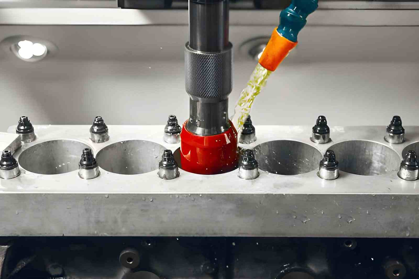
The image shows a CNC honing process used to finish engine cylinder walls and reduce surface roughness (iStock)
- Surface grinding is selected when flatness, parallelism, and tight dimensional control are critical on external surfaces after milling or heat treatment.
- CNC Milling is preferred for bulk material removal and general shaping, where moderate tolerance and faster cycle time are acceptable.
- Honing is used for internal cylindrical surfaces that require improved roundness, surface finish, and oil retention properties.
- Lapping is chosen for ultra-precision surfaces where contact accuracy and surface sealing are critical at micro-level tolerance.
When comparing surface grinding vs CNC milling, milling is typically used for shaping the part and creating most features, while surface grinding is chosen when the part needs better flatness, tighter tolerance control, or a smoother final surface.
Decision guideline:
- Choose milling for shaping and pre-finishing work.
- Choose surface grinding when flatness and tight tolerance define the function.
- Move to honing or lapping only when surface interaction or sealing demands exceed grinding capability.
Applications of Precision Surface Grinding
Surface grinding is used when the function of a part depends on stable contact surfaces rather than shape complexity.
It is mainly selected after milling or heat treatment when dimensional stability and surface behavior become critical.
Mold, Die, and Tooling Components
- Mold and die surfaces require tight flatness control so parting lines close evenly under load without leakage or mismatch.
- Tooling plates depend on ground surfaces to maintain consistent alignment between guiding and forming elements during repeated cycles.
- Wear during production makes re-grinding necessary to restore geometry without changing the overall tool assembly reference.
Machine Base and Structural Interfaces
- Machine bases rely on ground interfaces to distribute load evenly across guideways and structural joints.
- Misalignment at these surfaces directly affects machine positioning accuracy and long-term rigidity.
- Grinding ensures optimal assembly contact, especially in multi-part machine frames and fixtures.
Hardened and Wear-Resistant Parts
- Hardened components are ground because conventional cutting tools cannot maintain geometry after heat treatment.
- Wear surfaces require a controlled finish so contact stress is evenly distributed during sliding or repeated loading.
- Final grinding corrects distortion from heat treatment and maintains dimensional stability in critical regions.
Common Problems and How to Fix Them
Surface grinding problems appear when heat generation, wheel condition, or system rigidity moves outside stable limits. These issues show up directly on the workpiece as burn marks, loading on the wheel, or vibration patterns on the surface. In most cases, defects are linked to process imbalance rather than machine malfunction.
Grinding Burn and Thermal Damage
- Local grinding temperature can exceed 600–900°C when heat is not removed efficiently, leading to surface oxidation and microstructural change.
- Uneven cooling causes thermal expansion during cutting, which results in size variation after the part returns to room temperature.
Fix: Thermal Control and Cutting Adjustment
- Maintain coolant flow between 8 and 15 L/min with direct nozzle impact on the grinding zone.
- Reduce the depth of cut to below 0.01 to 0.02 mm during finishing stages.
- Keep wheel surface speed in the 25 to 30 m/s range for a stable heat balance.
Wheel Loading and Surface Defects
- Chip material can clog abrasive grains, reducing cutting action and increasing frictional rubbing on the surface.
- Loaded wheels increase surface roughness, often pushing Ra values above 1.6 to 3.2 µm in steel grinding.
Fix: Wheel Conditioning and Process Stability
- Dress the wheel frequently to restore cutting edges and remove embedded material.
- Use open-structure wheels for ductile materials to improve chip evacuation.
- Lower feed rate when chip accumulation becomes visible on the wheel surface.
Chatter and Surface Waviness
- Vibration between the wheel and workpiece creates repeating surface patterns that affect flatness and visual finish.
- Long overhang and weak fixturing amplify resonance effects, especially in finishing passes.
Fix: Stability and Setup Control
- Minimize wheel overhang and improve workpiece clamping rigidity.
- Adjust spindle speed ±10–15% away from vibration resonance zones.
- Reduce infeed below 0.01 mm during final finishing passes.
When Surface Grinding Becomes Expensive
The main cost drivers are longer machining time, repeated finishing cycles, and higher rejection risk due to thermal or geometric instability. As tolerances tighten, process flexibility drops, and production efficiency reduces sharply.
Tight Tolerances and Additional Finishing Passes
- When tolerance goes below ±0.01 mm, operators often add 2–3 finishing passes instead of a single pass to stabilize size correction.
- Each additional finishing pass increases setup time and tool dressing frequency, especially when maintaining flatness below 0.005 mm.
Low Material Removal Rate vs Cycle Time
- Surface grinding typically removes only 0.005 - 0.05 mm per pass, which makes bulk stock removal significantly slower than milling.
- Large surface areas can extend cycle time 2 - 4× compared to milling, especially when the feed is reduced below 3 m/min for finish control.
Scrap Risk from Thermal Distortion
- Excess heat during grinding can cause localized expansion of 0.01–0.03 mm, which later appears as a dimensional error after cooling.
- Thin or uneven parts may distort after machining, leading to rejection when flatness exceeds 0.01 mm tolerance limits.
Surface grinding becomes more difficult to control when tolerance is tight, heat builds up quickly, or the part itself is prone to movement. In those cases, the machining route is worth reviewing before production begins.
Not sure if surface grinding is necessary for your part?
Upload your CAD file to JLCCNC and get engineering feedback on tolerances, flatness, and the most cost-effective process — starting from $1 with lead times as fast as 3 days.

Precision CNC Machining Service
Professional manufacturing, fast turnaround, and quality assurance.
FAQs About Surface Grinding
Q:What is surface grinding used for
Surface grinding produces flat, controlled metal surfaces after machining or heat treatment. Engineers apply it when parts require tight fit control, stable contact, or accurate flatness for assembly. It is common in tooling, fixtures, and precision mechanical components.
Q: What is a surface grinder?
A surface grinder removes thin layers of material using a rotating abrasive wheel. The workpiece stays fixed on a magnetic chuck while the wheel moves across it in controlled passes. This process controls flatness, parallelism, and surface consistency through small incremental removal.
Q: Is surface grinding more accurate than milling?
Surface grinding provides higher flatness accuracy than milling on finished surfaces. Abrasive cutting removes material in controlled micro-layers, which improves dimensional stability. While milling focuses on material shaping, grinding corrects the final geometry.
Q: What materials can be surface ground?
Surface grinding works on hardened steels, tool steels, cast iron, and wear-resistant alloys. These materials hold shape under abrasive contact without surface collapse. It also handles heat-treated parts where cutting tools cannot maintain precision.
Popular Articles
• Cutting with Precision: A Comprehensive Guide to CNC Water Jet Technology
• CNC Coolant Explained: Types, Maintenance & Safety
• Rake Angle in Machining: Machinists’ Guide to Perfect Cuts
• What Steps Are Taken To Minimize Waste In CNC Machining Processes?
• How EDM Wire Cutting Works: Complete Guide to Precision CNC Wire Cutting
Keep Learning
Chatter in Machining: Causes, Effects, and How to Reduce It
CNC milling operation producing visible chatter marks on an aluminum workpiece Quick Chatter Diagnosis Checklist Symptom Most Likely Cause First Action High-pitched squeal Regenerative chatter Change spindle speed ±15% Chatter only in deep pockets Excessive tool overhang Shorten tool Chatter on thin walls Low workpiece rigidity Improve fixturing Chatter after tool replacement Runout / holder issue Check tool holder Chatter only during finishing DOC too small / rubbing Increase feed or adjust speed It ......
What Is Tool Offset in CNC? Types, Setup & Best Practices
CNC tool offset setup with measurement overlay Key Takeaways CNC offsets connect programmed intent with actual cutter position. Length data guides Z-axis depth control. Radius data protects part size during contour milling. Geometry values define the cutter's measured baseline. Wear values support fine correction during production. Verified data lowers scrap risk before full machining. Good offset habits protect tools, fixtures, and parts. In the context of CNC machining , tool offset is the quiet set......
Trochoidal Milling: Complete Guide to High-Efficiency CNC Machining
Key Takeaways Trochoidal milling combines circular cutter motion with continuous forward feed. The cutter normally engages 5 to 20% of its diameter instead of making a full-width cut. A smaller engagement angle limits force changes during slotting and pocket roughing. Low radial engagement often allows greater axial depths of cut than conventional slot milling. CAM software calculates the circular path automatically from the selected machining parameters. This strategy is widely applied to titanium, s......
What Is Die Casting? Process, Materials, and Applications
Key Takeaways Die casting is a metal casting process that forces molten metal into a reusable steel mold under high pressure, producing parts with tight tolerances and good surface finish at high volume. Aluminum die casting is the most common form by far, thanks to its combination of light weight, decent strength, and good corrosion resistance. The die casting process runs through mold preparation, injection, cooling, and ejection in a cycle that can repeat every few seconds to minutes depending on p......
First Angle vs Third Angle: Understanding Orthographic Projection Methods
Key Takeaways Orthographic projection is the system that lets a 3D part be represented through multiple 2D views, front, top, side, and so on. First angle projection and third angle projection are the two standard methods for arranging those views, and they place views in opposite positions relative to the object. First angle projection is the ISO standard used across most of Europe, India, China, Russia, and many other countries following ISO standards Third angle projection is the standard in the Un......
Micro EDM Machining: Capabilities, Materials, and Applications for Precision Components
Key Takeaways About Micro EDM Machining Only electrically conductive materials can be machined. Hole diameters can reach below 50 μm on specialized equipment. The process produces almost no mechanical cutting force, making it suitable for thin or delicate features. Surface integrity still requires attention because recast layers and heat-affected zones may remain after machining. Micro EDM is often combined with CNC machining, with milling producing the main geometry before EDM finishes critical micro......