True Position in GD&T: Symbol, Formula, Tolerance, and Manufacturing Applications
23 min
- What Is the True Position in GD&T?
- Understanding the True Position Symbol and Feature Control Frame
- How True Position Tolerance Works
- True Position Formula and Calculation Examples
- How True Position Is Measured
- Common Applications of True Position
- True Position and CNC Machining
- Maintaining True Position During CNC Machining
- Common Mistakes When Applying True Position
- Conclusion About True Position in GD&T
- FAQ About True Position
Key Takeaways About True Position
- True position defines the allowable variation in a feature's location from its basic dimensions.
- The control applies to holes, slots, pins, threaded features, and datum features.
- A circular tolerance zone controls features in 2D, while a cylindrical zone controls feature axes in 3D.
- Datum references establish the coordinate system used for manufacturing and inspection.
- Maximum Material Condition (MMC) adds bonus tolerance as the feature departs from its maximum material size.
- Coordinate measuring machines (CMMs), vision systems, and functional gauges are common inspection methods.
- True position reduces coordinate dimensioning while providing a clear positional requirement on engineering drawings.
Feature size alone does not define part geometry. The location of a hole, slot, pin, bearing bore, and threaded feature also affects assembly, inspection, and machining. A feature may satisfy its size tolerance while its center shifts beyond the specified location.
True position controls this positional variation by defining the allowable distance between the feature's theoretical location and its manufactured location. Instead of assigning separate limits to the X and Y coordinates, GD&T establishes a single tolerance zone referenced from one datum system.
Engineering drawings frequently apply true position to hole patterns, dowel locations, bearing seats, mounting interfaces, connector layouts, and fixture points. This method simplifies dimensioning, provides a consistent inspection requirement, and supports interchangeable components across production batches.
This article explains the true position symbol, tolerance zones, calculation methods, MMC bonus tolerance, inspection techniques, manufacturing considerations, and common engineering applications.
What Is the True Position in GD&T?
GD&T True Position (Mechademic)
Every manufactured feature occupies a physical location on the part. During production, small variations naturally occur, even though the nominal dimensions remain unchanged. True position establishes the maximum positional variation allowed for that feature while using the specified datum reference frame as the measurement origin. Rather than controlling individual X and Y dimensions, the drawing defines a single geometric requirement that represents the feature's intended location.
This control appears on holes, slots, locating pins, bearing bores, threaded features, and multi-hole patterns because these features must maintain their relationship with surrounding geometry. The drawing uses basic dimensions to define the theoretical location, while the feature control frame specifies the allowable positional variation. Manufacturing, inspection, and assembly all reference the same datum structure, reducing interpretation differences throughout production.
‘True position is a GD&T control that defines the allowable positional variation of a feature from its basic dimensions using a specified datum reference frame’
Why Position Is a Fundamental GD&T Control
Composit positional tolerancing (CMM Manager)
Part dimensions answer one question: feature size. They do not establish whether the feature occupies the intended location on the component. A hole may satisfy its diameter specification, yet its center can shift enough to affect the alignment of dowel pins, bearings, fasteners, mating plates, and fixture locations. Size inspection alone cannot identify this condition.
True position adds an independent location requirement without increasing drawing complexity. Every controlled feature references the same datum system, allowing inspection equipment to evaluate the feature against one consistent coordinate structure instead of multiple linear dimensions. Designers also gain greater flexibility for complex layouts because a complete hole pattern can be controlled with one positional callout rather than assigning individual tolerances to every spacing dimension.
True Position vs Coordinate Dimensioning
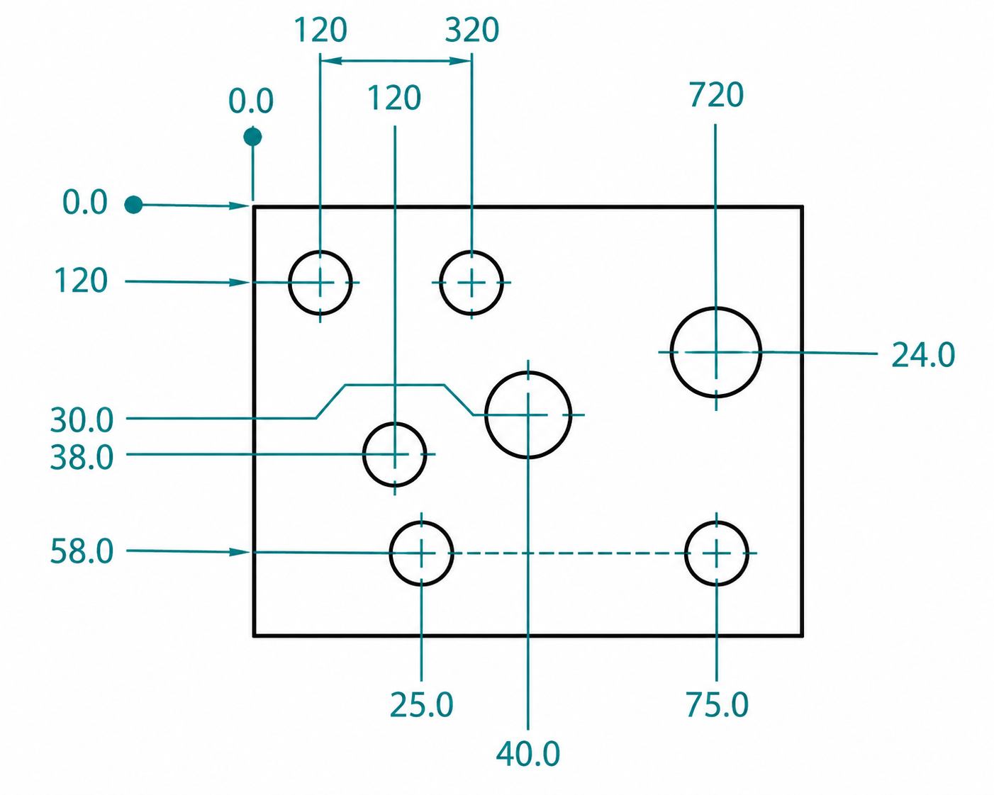
Coordinate Dimension (soliddna.com)
Coordinate dimensioning evaluates each linear dimension independently. Every X and Y value receives its own tolerance, requiring inspectors to verify numerous measurements before determining whether the feature location satisfies the drawing. As additional holes and locating features are introduced, both dimensioning and inspection become progressively more complicated.
True position approaches the same requirement differently. Basic dimensions establish the exact feature location, while a single geometric tolerance defines the allowable variation around that location. Inspection evaluates the complete feature instead of separate coordinate values, providing a consistent acceptance method for CNC machining, CMM inspection, functional gauges, and automated measurement systems.
| Engineering Consideration | True Position | Coordinate Dimensioning |
|---|---|---|
| Feature definition | Controls the complete feature location | Controls each linear coordinate independently |
| Drawing method | Uses basic dimensions with one feature control frame | Uses multiple coordinate dimensions with individual tolerances |
| Inspection approach | Evaluates the complete feature relative to the datums | Verifies each coordinate dimension separately |
| Hole patterns | One positional callout controls the entire pattern | Every spacing dimension requires separate verification |
| Tolerance accumulation | Reduces accumulated dimensional variation | Multiple coordinate tolerances can accumulate across the layout |
| Drawing clarity | Fewer dimensions with a structured GD&T callout | A larger number of dimensions and tolerance values |
| Common engineering use | Precision locating features, bearing bores, dowel holes, and mounting patterns | Simple layouts with limited positional requirements |
Understanding the True Position Symbol and Feature Control Frame
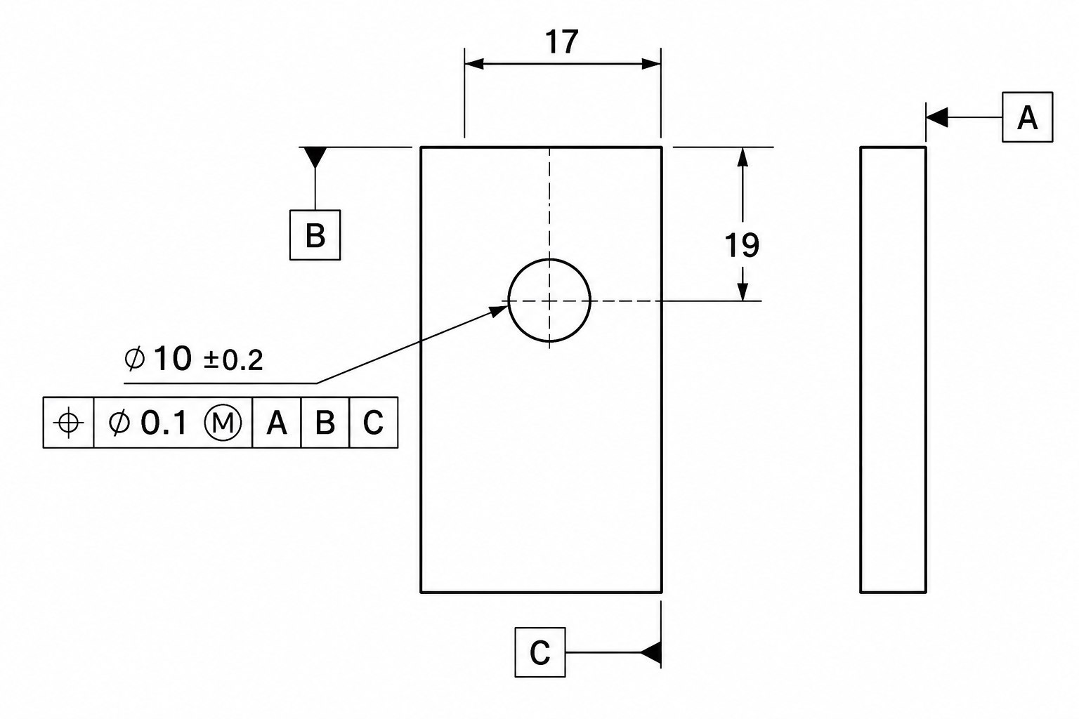
A true position requirement appears inside a feature control frame instead of being assigned through conventional dimensional tolerances. This notation defines the allowable positional variation, the datum reference sequence, and any material condition modifiers used during manufacturing and inspection. Engineers read the feature control frame together with the basic dimensions because both elements define the complete positional requirement.
Every symbol inside the feature control frame has a specific purpose. The geometric characteristic identifies the applied control, the tolerance value defines the permissible variation, datum references establish the measurement origin, and optional modifiers change how the tolerance is evaluated. Reading these elements in the correct sequence prevents drawing interpretation errors during machining, inspection, and assembly.
The True Position Symbol
True position GD&T symbol (Amazon S3)
The true position symbol is the first element inside the feature control frame. It identifies the geometric control applied to the selected feature.
- The position symbol (⌖) specifies positional control instead of size, flatness, parallelism, angularity, and other GD&T characteristics.
- The symbol applies to holes, pins, slots, tabs, threaded features, datum targets, center planes, and feature patterns.
- The control limits the feature axis, center point, and center plane, depending on the feature type shown on the drawing.
- Position requirements always reference basic dimensions, which appear inside rectangular boxes without dimensional tolerances.
- Circular features typically use a cylindrical tolerance zone, while non-cylindrical features may use different tolerance zone definitions specified by the drawing standard.
- The symbol always appears inside the feature control frame instead of being attached directly to a linear dimension.
Components of a Feature Control Frame
The feature control frame combines every requirement needed to evaluate feature position. Reading the symbols from left to right provides the complete inspection requirement.
- Geometric characteristic symbol (⌖) identifies true position as the applied GD&T control.
- Tolerance value (⌀0.20, 0.10, etc.) specifies the allowable positional variation.
- The diameter symbol (⌀) indicates a cylindrical tolerance zone around the theoretical feature axis.
- Material condition modifiers such as Ⓜ (MMC) and Ⓛ (LMC) adjust the available positional tolerance according to feature size.
- Datum references (A, B, C) establish the coordinate system used during machining and inspection.
- Datum sequence defines the order of part restraint, beginning with the primary datum, followed by the secondary and tertiary datums.
- Multiple feature control frames may appear on a drawing if different features require independent positional controls.
Datum References and Feature Location
- Primary datum (A) removes three degrees of freedom and establishes the primary locating surface.
- Secondary datum (B) restricts additional movement while orienting the part.
- Tertiary datum (C) completes the datum reference frame by removing the remaining rotational movement.
- Basic dimensions locate every controlled feature from the selected datum reference frame.
- Hole patterns, slots, locating pins, bearing bores, and mounting interfaces commonly reference the same datum structure to maintain positional consistency.
- Datum selection typically follows functional surfaces used during assembly, machining, and inspection instead of convenient external edges.
How to Read a Position Callout
A position callout should be read from left to right because every compartment adds a specific inspection requirement.
- Identify the position symbol (⌖) to confirm the applied geometric control.
- Read the tolerance value and determine whether the diameter symbol (⌀) defines a cylindrical tolerance zone.
- Check for MMC (Ⓜ), LMC (Ⓛ), and Regardless of Feature Size (RFS) conditions before evaluating feature size.
- Read the datum references in sequence, such as A | B | C, because the order establishes the measurement coordinate system.
- Locate the associated basic dimensions, which define the theoretical feature location without plus-minus tolerances.
- Verify that the feature size satisfies its dimensional tolerance before evaluating the positional requirement during inspection.
How True Position Tolerance Works
GD&T position tolerance defines how far a feature can deviate from its theoretically exact location.
A true position tolerance creates a defined geometric boundary around the feature's exact location, shown by the basic dimensions. Instead of assigning separate limits to horizontal and vertical distances, the drawing establishes one positional requirement referenced from the selected datum system. Every measured feature is evaluated against this boundary after datum alignment, allowing manufacturing and inspection teams to use the same acceptance criteria throughout production.
Cylindrical Tolerance Zone Explained
Most positional callouts applied to holes and pins use a cylindrical tolerance zone because these features are manufactured around a center axis. The specified tolerance value defines the diameter of an imaginary cylinder centered on the theoretical location. During inspection, the measured axis must remain inside this cylinder. Small deviations are permitted in any direction, provided the axis never crosses the cylindrical boundary. This evaluation reflects the functional behavior of round features far better than checking separate X and Y limits.
True Position Tolerance for Holes
A hole is evaluated by its center axis rather than its outer edge. This distinction becomes important after drilling, boring, reaming, and finishing operations because the hole diameter may remain within specification while the axis shifts slightly from its intended location. Position tolerance separates these two requirements. Diameter controls feature size, while true position controls axis location. Both values are verified independently before the part satisfies the drawing specification.
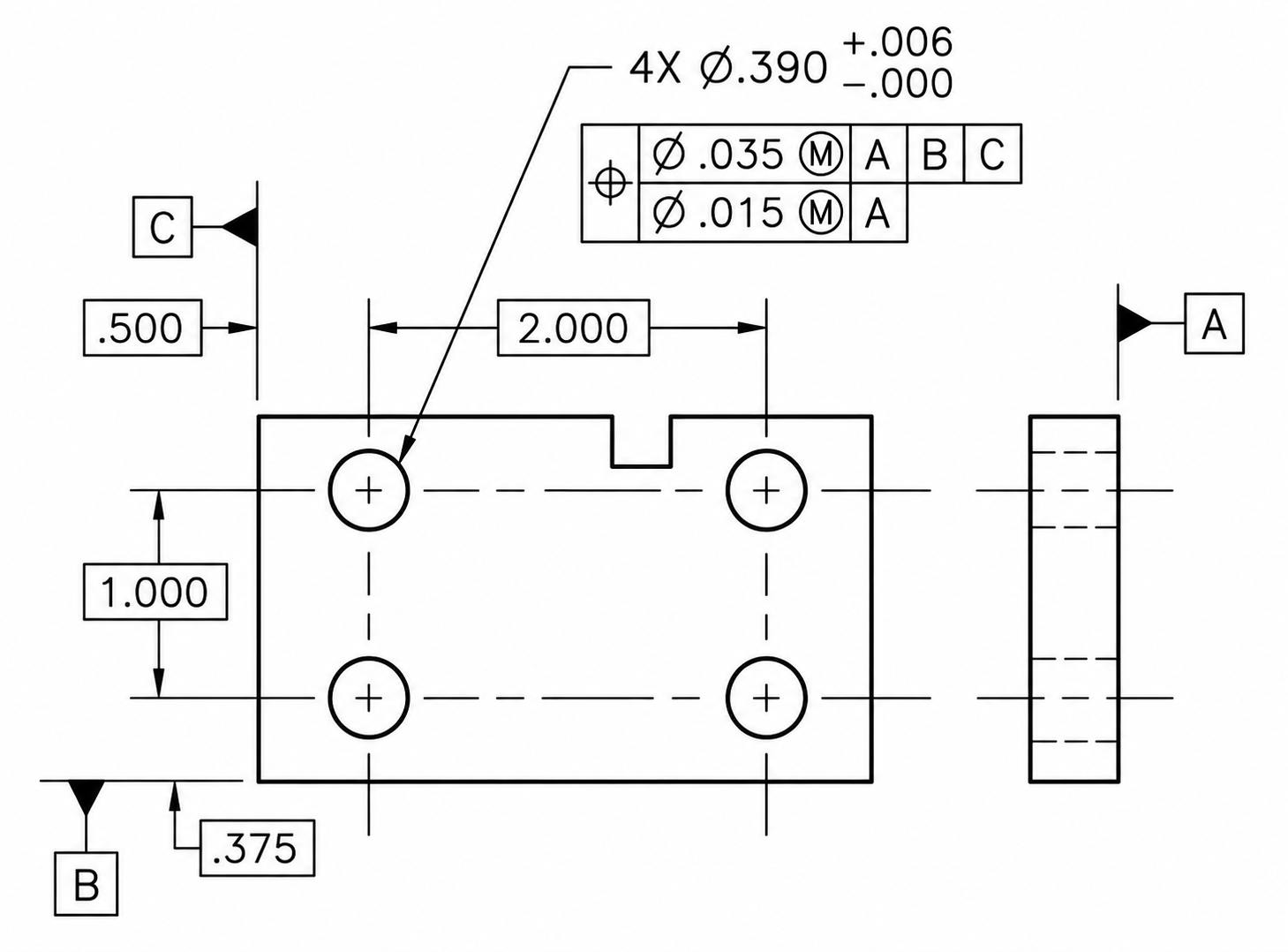
Position Control for Hole Patterns
Engineering drawings frequently apply one position callout to an entire hole pattern instead of assigning individual coordinate tolerances to every hole. This approach keeps every feature referenced from the same datum structure while preserving the intended relationship between holes. Bolt circles, mounting plates, electronic housings, and fixture bases commonly follow this method because assembly depends on the combined location of the pattern rather than one isolated hole.
Position Requirements for Pins and Features
Position control is not limited to holes. Cylindrical pins, locating bosses, shafts, studs, and similar external features are inspected using the same positional principle because each feature also has a theoretical center axis. The inspection process evaluates that axis after establishing the datum reference frame. Although the feature geometry changes from internal to external, the positional requirement follows the same GD&T concept.
True Position Formula and Calculation Examples
A true position value is calculated by comparing the measured feature location with the theoretical location defined by the basic dimensions. The calculation converts the X and Y deviations into a single positional value, allowing inspectors to evaluate the feature against one geometric tolerance instead of separate coordinate measurements. This method is commonly used in CMM inspection reports, first article inspections, and production quality verification.
The True Position Formula
Position error is determined from the difference between the theoretical coordinates and the measured coordinates of the feature center. The calculation combines both coordinate deviations into one positional value.
The standard formula is:
True Position = 2 × √[(ΔX)² + (ΔY)²]
Where:
- ΔX = Difference between the nominal X location and measured X location.
- ΔY = Difference between the nominal Y location and measured Y location.
- 2 × converts the radial deviation into a diametrical positional value because GD&T position tolerances are specified as diameter values.
The calculated result is then compared with the position tolerance specified in the feature control frame.
Calculating Position Error
The calculation begins by locating the theoretical feature center from the basic dimensions. The inspection equipment then records the measured feature center after establishing the datum reference frame.
The coordinate differences are calculated independently before applying the position formula. Although each coordinate contributes to the final value, the acceptance decision depends on the combined positional error rather than the individual X and Y deviations. This approach eliminates separate acceptance limits for each coordinate and evaluates the feature using one positional value.
Example of True Position Evaluation
Assume a hole has a basic location of X = 50.00 mm and Y = 30.00 mm.
Inspection reports the measured center as:
- Measured X = 50.08 mm
- Measured Y = 29.95 mm
Coordinate deviations become:
- ΔX = 0.08 mm
- ΔY = −0.05 mm
Applying the formula:
True Position = 2 × √[(0.08)² + (0.05)²]
= 2 × √(0.0064 + 0.0025)
= 2 × 0.094
= 0.188 mm
If the drawing specifies ⌖ ⌀0.20, the measured position of 0.188 mm satisfies the positional requirement.
Interpreting Calculation Results
The calculated position value represents the feature's total positional deviation from its theoretical location. Inspection software automatically compares this value with the tolerance specified in the feature control frame.
- A calculated value equal to or below the specified tolerance is acceptable.
- A calculated value greater than the specified tolerance does not satisfy the drawing requirement.
- If the drawing applies MMC, additional bonus tolerance may increase the allowable positional variation based on the measured feature size.
The reported value should always be interpreted together with the feature control frame because material condition modifiers can change the allowable limit.
Difference Between True Position and Position Tolerance
These terms are closely related, though they describe different parts of the inspection process.
| Term | Description |
|---|---|
| True Position | The calculated positional error is obtained from the measured feature coordinates. |
| Position Tolerance | The maximum positional variation permitted by the engineering drawing. |
| Source | Generated during inspection measurements. |
| Value | Changes for every measured feature. |
| Purpose | Determines the measured feature location. |
| Inspection Decision | Compared directly with the specified position tolerance. |
In engineering drawings, tolerance position requirements define acceptable feature location variation.
Position tolerances are closely tied to machining capability as well as inspection strategy. Before production begins, it is often worth reviewing the drawing to confirm that datum references, tolerance values, and feature layouts can be manufactured and verified without unnecessary complexity.
JLCCNC provides engineering review and DFM feedback during the quotation process for CNC-machined parts with GD&T requirements. Upload your CAD files to request a quote and design review.

Precision CNC Machining Service
Professional manufacturing, fast turnaround, and quality assurance.
How True Position Is Measured
Position verification begins after the part is aligned with the datum reference frame defined on the drawing. The inspection method depends on feature geometry, production quantity, inspection time, and reporting requirements. Some methods provide numerical measurement data, while others simply confirm whether the feature satisfies the specified positional requirement.
CMM Inspection
- A CMM measures the center location of each feature and compares it with the theoretical coordinates defined by the basic dimensions. The software automatically reports the calculated true position value.
- This method is commonly selected for precision components, first article inspection, multi-feature parts, and applications requiring complete dimensional reports.
Functional Gauging
- Functional gauges check whether pins, holes, and mating features assemble correctly without calculating the actual position error. The result is simply pass or fail.
- Production lines frequently use this method because parts can be inspected within seconds without programming a measuring system.
Optical Measurement Systems
- Cameras and optical sensors capture feature locations without contacting the part, making them suitable for polished surfaces, thin sections, and delicate components.
- Multiple holes and feature patterns can be measured in one inspection cycle, reducing inspection time for high-volume production.
Inspection Challenges for Tight Position Tolerances
- Datum surfaces containing burrs, chips, surface damage, and poor fixturing can shift the measurement reference before the feature is inspected.
- Tool wear, thermal expansion, machine calibration, and probing strategy can introduce small measurement differences, particularly on precision-machined components.
Common Applications of True Position
Position tolerances are assigned to features whose location defines the finished part geometry. The drawing may contain dozens of dimensions, though only selected features receive a position callout because those features establish the reference points used during assembly, inspection, machining, and secondary operations. The following examples appear frequently across CNC-machined components.
Fastener Hole Patterns
A flange containing eight mounting holes illustrates a common position control application. Every hole must align with the matching pattern on the mating flange, not simply satisfy its diameter tolerance. Basic dimensions establish the theoretical bolt circle, while one position callout controls the entire pattern. This approach removes the need to tolerate every hole spacing independently and keeps the drawing much easier to interpret.
Locating Features in Assemblies
Locating holes and dowel pins establishes the position of a component before bolts are tightened. Designers normally assign position tolerances to these features first because they define the assembly reference for the remaining geometry. Once the locating features engage, clearance holes simply accommodate the fasteners rather than determine component alignment.
Automotive and Aerospace CNC Components
An engine housing may pass through milling, drilling, boring, tapping, and finishing before the final inspection stage. Every operation references the same datum structure shown on the engineering drawing. Position tolerances preserve the intended relationship between bearing bores, threaded holes, dowel locations, and mounting faces throughout the complete machining sequence.
Precision CNC-Machined Parts
Tooling plates, semiconductor fixtures, hydraulic manifolds, and medical instruments frequently contain intersecting hole networks produced during separate machining operations. Position control verifies the completed feature layout against one datum reference frame instead of checking every coordinate dimension individually. The inspection report also becomes easier to review because the positional deviation is reported for each controlled feature rather than for dozens of separate dimensions.
True Position and CNC Machining
A position tolerance influences the complete manufacturing route, not only the finished dimension. Fixture selection, machining sequence, inspection planning, and process capability are all considered before the first cutting operation begins. As positional requirements become more demanding, machining variation becomes progressively more difficult to control across every operation.
Position Tolerance and Machining Accuracy
- Establish the datum surfaces during the first CNC setup, so every critical feature references the same machining origin.
- Machine locating holes and precision bores after rough milling to reduce positional changes caused by material removal.
- Keep the part in one fixture whenever practical because every additional setup introduces another alignment step.
- Finish the datum features before machining position-controlled features so the machining reference remains consistent.
Inspection Requirements and Quality Control
- Confirm the datum setup before checking feature location because an incorrect reference affects every measurement.
- Compare feature size and feature position separately since both requirements appear independently on the drawing.
- Inspect the first completed part before production continues to identify setup adjustments early.
- Review position results across several parts instead of evaluating one measurement in isolation.
Cost Implications of Position Tolerances
- Smaller positional values increase setup time because fixtures require more accurate alignment.
- Additional finishing operations may be introduced to improve feature location after rough machining.
- Longer inspection cycles become part of production because more controlled features require verification.
- Position requirements should reflect the functional purpose of the feature rather than applying the same value across the entire drawing.
Design Recommendations for Manufacturability
- Apply position tolerances only to features controlling alignment, assembly, and component location.
- Select datum features that can support machining, inspection, and assembly without changing the reference system.
- Dimension complete feature patterns from one datum structure instead of creating multiple independent coordinate chains.
- Leave generous positional limits on non-functional features so machining time is focused on critical geometry.
Maintaining True Position During CNC Machining
Plan Datum Features Early
A position tolerance is only as reliable as the datum structure used to machine the part. In practice, many shops establish the primary datum during the first setup and avoid changing the reference unless the process requires it. Once the datum surfaces have been finish machined, the remaining position-controlled features can reference the same coordinate system throughout production.
This becomes more important on parts that pass through several operations. Re-establishing the work coordinate after every setup increases the chance of small alignment shifts, even when each individual setup is within machine capability.
Reduce Position Error Between Setups
Additional setups do not automatically create poor positional accuracy, but every relocation introduces another opportunity for variation. Fixture repeatability, locating pins, clamping force, and thermal stability all influence the final feature location.
For example, a housing may be rough milled in one setup and then rotated to machine the opposite face. If the locating surfaces change between operations, hole position can drift even though each machining operation meets its own dimensional requirements. When practical, manufacturers often finish critical locating holes and precision bores within the same setup used to establish the datum reference.
Control Tool Wear Before Position Drifts
Position errors are not always caused by fixture alignment. As cutting tools wear, feature location may gradually move because cutter diameter changes, tool deflection increases, or thermal growth affects machining conditions during long production runs.
Many shops monitor the first production parts before adjusting wear offsets. On tighter position tolerances, probe measurements or periodic in-process inspection may be used to verify feature location before dimensional variation reaches the specified limit.
Verify Position Using the Same Datum Reference
Inspection should follow the datum reference established during machining rather than the easiest surface to measure. A coordinate measuring machine, functional gauge, or optical system first establishes the specified datums before calculating positional deviation.
Inspection planning often begins before machining starts. Engineers may leave enough clearance around critical holes so the probe can reach them without interference, or reserve reference surfaces that remain accessible after finishing operations. Small design decisions like these usually make production inspection more repeatable, especially on parts containing multiple position-controlled features.
Common Mistakes When Applying True Position
A position tolerance should reflect the function of the feature, not simply add another GD&T requirement to the drawing. Many inspection issues begin during the design stage through datum selection, tolerance assignment, material condition modifiers, and process planning. Small changes in these areas can simplify manufacturing while avoiding unnecessary inspection effort.
Choosing Poor Datum Structures
- Selecting unfinished, curved, or unstable surfaces as datums creates inconsistent part alignment during machining and inspection.
- Datum features should represent the surfaces that locate the part in the finished assembly, not simply the easiest dimensions to reference.
- Changing datum references between related features can produce conflicting measurement results on the same component.
Applying Excessively Tight Position Tolerances
- Assigning the same positional value to every feature increases machining and inspection effort without adding functional value.
- Clearance holes rarely require the same positional control as locating holes, dowel holes, and bearing bores.
- Position tolerances should match the purpose of the feature rather than applying one common value across the drawing.
Misunderstanding MMC and Bonus Tolerance
- Bonus tolerance becomes available only if the feature control frame includes the MMC modifier.
- Feature size limits remain unchanged even though the available position tolerance can increase.
- MMC should be selected only if additional positional variation does not affect the intended assembly fit.
Ignoring Manufacturing Capability
- Multiple machining setups, long tools, thin sections, and part distortion can influence feature location during production.
- Position values should reflect the actual machining process, workholding method, and inspection capability before the drawing is released.
- Reviewing the drawing with manufacturing and quality teams early in the design stage reduces engineering changes after production begins.
Conclusion About True Position in GD&T
True position provides a practical way to control feature location when assembly depends on accurate alignment. Instead of managing multiple coordinate dimensions separately, designers can define the allowable positional variation with one GD&T control referenced to a stable datum system.
Applying true position effectively involves more than selecting a tolerance value. Datum selection, machining strategy, inspection planning, and the function of the feature all influence whether the specified requirement can be achieved consistently in production. Matching the position tolerance to the actual design requirement often leads to a process that is easier to manufacture and verify.
Position-controlled features often require machining and inspection to follow the same datum strategy defined on the drawing. Reviewing datum selection, feature accessibility, and tolerance requirements before production can help identify potential manufacturing issues early.
JLCCNC supports CNC machining for prototypes, low-volume production, and production batches. When drawings include GD&T controls such as true position, our engineering team reviews the manufacturability of the part and provides Design for Manufacturability (DFM feedback as part of the quotation process.
Upload your CAD files to receive a CNC machining quote and an engineering review before production begins.
Precision CNC Machining Service
Professional manufacturing, fast turnaround, and quality assurance.
FAQ About True Position
Q: What is the true position in GD&T?
True position is a GD&T control that defines the allowable variation in a feature's location from its basic dimensions. The requirement is evaluated from the specified datum reference frame and applies to the feature center, axis, and center plane, depending on the feature geometry shown on the drawing.
Q: What is the true position formula?
The standard calculation is:
True Position = 2 × √[(ΔX)² + (ΔY)²]
The formula combines the X and Y deviations into one positional value. Inspection software normally performs this calculation automatically after measuring the feature coordinates.
For planar hole location checks, the common calculation uses X and Y deviation. In 3D applications, Z deviation may also be included depending on feature requirements and inspection method.
Q: What is the true position symbol?
The true position symbol is ⌖. It appears as the first symbol inside the feature control frame, followed by the tolerance value, optional material condition modifiers, and the required datum references.
Q: What is the difference between true position and positional tolerance?
True position is the measured deviation of a feature location, while positional tolerance is the allowable limit specified on the drawing.
Q: Can CNC machining achieve true position tolerance?
Yes. CNC machining can achieve true position requirements when datum setup, fixturing, tool control, and inspection methods are properly planned.
Q: How is the true position measured?
Position verification starts by establishing the datum reference frame shown on the drawing. The feature location is then measured using equipment such as a CMM, functional gauge, optical measurement system, and compared with the specified position tolerance.
Q: What is bonus tolerance?
Bonus tolerance is additional positional variation generated as a feature departs from its Maximum Material Condition (MMC). The bonus value equals the difference between the actual feature size and its MMC size, increasing the total available position tolerance.
Q: What is MMC in position tolerance?
Maximum Material Condition (MMC) represents the feature size containing the greatest amount of material. For a hole, MMC is the smallest permitted diameter. For a pin, MMC is the largest permitted diameter. Position tolerances specified with the MMC modifier can gain bonus tolerance as the measured feature departs from this condition.
Q: How does true position differ from coordinate tolerancing?
Coordinate tolerancing controls each linear dimension independently using plus-minus values. True position controls the complete feature location with one geometric tolerance referenced from basic dimensions and datum features. This approach simplifies complex drawings containing hole patterns and locating features.
Q: How does true position affect CNC machining cost?
Position tolerance influences setup strategy, fixturing, machining sequence, and inspection time. Smaller positional values generally require additional setup verification, closer process control, and longer inspection cycles. Position tolerances matched to the functional requirement usually avoid unnecessary manufacturing cost while maintaining the intended part function.
Keep Learning
Types of Holes in Engineering: Design, Symbols, and Manufacturing Guide
Types of holes in engineering - illustration (Erye rubber & plastic parts) Key Takeaways Engineering holes are used to support fastening, alignment, bearing installation, fluid flow, and other functional requirements. The main types of holes include through holes, blind holes, threaded holes, counterbore holes, countersink holes , spotface holes, screw clearance holes, reamed holes, and dowel holes. Hole geometry determines the required machining process. Some holes only require CNC drilling , while o......
True Position in GD&T: Symbol, Formula, Tolerance, and Manufacturing Applications
Key Takeaways About True Position True position defines the allowable variation in a feature's location from its basic dimensions. The control applies to holes, slots, pins, threaded features, and datum features. A circular tolerance zone controls features in 2D, while a cylindrical zone controls feature axes in 3D. Datum references establish the coordinate system used for manufacturing and inspection. Maximum Material Condition (MMC) adds bonus tolerance as the feature departs from its maximum materi......
Tolerance Stack-Up: Analysis, Examples, and How It Affects Manufacturing and Assembly
Key Takeaways About Tolerance Stack-Up Tolerance stack-up determines the dimensional variation that accumulates across multiple features and assembled parts. The stack-up study allows engineers to identify gaps, interference issues, alignment shifts, and fit conditions before production starts. Small dimensional variations from several parts can combine and create larger assembly issues. Usually, worst-case analysis evaluates the maximum possible variation by combining all tolerance limits. Statistica......
How to Read Engineering Drawings: Symbols, Dimensions, and Practical Interpretation
Key Takeaways About Engineering Drawings Engineering drawings communicate product requirements throughout manufacturing, inspection, assembly, and quality control. They communicate information that may not be fully defined in a CAD model, such as allowable variation, surface requirements, and inspection points. A drawing review starts with understanding the part reference system. The machinist checks which surfaces are used as datums, how features relate to each other, and which areas need access duri......
Design for Manufacturing (DFM): Principles, Guidelines, and Cost Reduction Strategies
Key Takeaways About DFM Design for manufacturing (DFM) is the process of designing products that are easier, faster, and less expensive to manufacture. Good DFM design reduces production cost long before a part reaches the factory floor. Most manufacturing costs are locked in during the design phase, not during production. Following proven design for manufacturing guidelines helps reduce machining time, material waste, tooling complexity, and assembly issues. Effective DFM improves product quality, sh......
Design for Cost in Manufacturing: DFM and Cost Reduction
Key Takeaways About Design for Cost Design for cost (DFC) integrates manufacturing cost into geometry, tolerance, material, and process decisions during early design definition. Design to cost engineering defines a target unit cost early and uses it as a design constraint alongside functional requirements. Most cost reduction potential exists during design definition, not during machining optimization or production tuning. In CNC manufacturing, cost is often driven by geometry complexity, tolerance ti......