Tolerance Stack-Up: Analysis, Examples, and How It Affects Manufacturing and Assembly
20 min
- How Tolerance Stack-Up Affects Part Fit and Assembly
- Tolerance Stack-Up Examples
- Tolerance Stack-Up Formulas and Calculations
- Methods of Tolerance Stack-Up Analysis
- How to Perform a Tolerance Stack-Up Analysis
- GD&T and Tolerance Stack-Up
- Factors That Increase Tolerance Stack-Up Risk
- How Engineers Reduce Tolerance Stack-Up Problems
- Balancing Tolerance Requirements and Manufacturing Cost
- Conclusion About Tolerance Stack-Up
- FAQ About Tolerance Stack-Up
Key Takeaways About Tolerance Stack-Up
- Tolerance stack-up determines the dimensional variation that accumulates across multiple features and assembled parts.
- The stack-up study allows engineers to identify gaps, interference issues, alignment shifts, and fit conditions before production starts.
- Small dimensional variations from several parts can combine and create larger assembly issues.
- Usually, worst-case analysis evaluates the maximum possible variation by combining all tolerance limits.
- Statistical analysis estimates likely assembly conditions based on expected manufacturing variation.
- GD&T provides a way to control how features relate to each other on a part. Instead of controlling only individual sizes, it defines relationships such as feature location, orientation, and alignment from established datums.
- Tolerance selection also requires a balance between design needs and manufacturing capability. Applying extremely narrow limits to every feature can increase machining difficulty, inspection requirements, and production cost without improving part performance.
One-dimensional geometric tolerance stack-up analysis (ResearchGate)
Tolerance decisions become more complex when multiple parts interact within an assembly. A dimension that appears acceptable when reviewed in isolation may affect the final assembly condition when it interacts with other features.
A small variation on one surface, hole, and locating feature may have little effect by itself. When multiple dimensions impact the same assembly requirement, the combined effect can affect the position, clearance, or alignment of a component.
This is a common issue that arises in many CNC-machined products, such as industrial equipment, automotive components, and precision assemblies. It is not always possible to predict how an assembly will perform by examining each dimension separately.
Tolerance stack-up analysis allows designers to study these relationships before production begins. It identifies which dimensions have the greatest influence and helps teams select practical tolerances that support both assembly requirements and manufacturing capability.
What Is Tolerance Stack-Up?
Tolerance stack up (Drafter)
In CNC machining, tolerance stack-up describes how dimensional and geometric variations from multiple features accumulate to affect a functional assembly requirement, such as clearance, alignment, or part location.
The outcome is determined by how those features relate to each other and by the tolerances of these features relative to the fit, position, and clearance.
How Tolerance Accumulation Occurs
Tolerance accumulation (Engineering Essentials)
Tolerance accumulation happens when several related dimensions contribute to one final measurement.
For example, a machined assembly may include:
- A housing bore location
- A bearing width
- A spacer thickness
- A shaft shoulder position
Individual part dimensions rarely determine the final assembly condition by themselves. The actual result depends on how those dimensions combine along the assembly path. If several features contribute to the same location, gap, or fit requirement, their allowable variation can increase or decrease the final condition.
Engineers evaluate this combined variation using different stack-up approaches. Some designs require checking the worst possible condition, while others use statistical methods to predict the most likely assembly result based on production variation. The right approach depends on how the product functions and how much variation the assembly can accept.
Why Tolerance Stack-Up Matters in Manufacturing
Tolerance stack-up affects part fit, alignment, and assembly quality. If dimensional variations add up beyond acceptable limits, they can cause assembly issues, poor performance, and extra rework.
Common examples include:
- Bearing locations: Misalignment can affect rotation and bearing life.
- Shaft supports: Accumulated variation can cause vibration and wear.
- Fastener hole patterns: Holes may not align during assembly.
- Valve and hydraulic components: Incorrect clearances can affect sealing and operation.
How Tolerance Stack-Up Affects Part Fit and Assembly
A tolerance stack-up problem appears when several small dimensional differences add together in one assembly. The effect is usually seen during fitting, alignment, movement, or final testing.
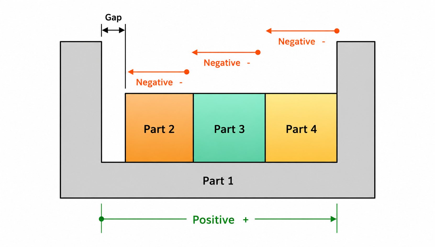
Clearance and Interference Conditions
Stack-up controls the final gap between mating parts. Individual dimensions do not always define the final fit of an assembly. The relationship between mating features determines whether the parts achieve the required clearance and function.
In a bearing application, accumulated variation between the shaft, bore, and seating surfaces can change the fit condition. The result may range from unwanted movement to difficult installation if the available clearance falls outside the intended range.
Alignment and Positional Errors
Stack-up can shift the relationship between features that must line up. This is common in assemblies with multiple holes, locating pins, shafts, or mounting surfaces.
A machined plate may have every hole within tolerance, but the total position variation can make bolt installation difficult if the mating pattern does not match.
Functional Performance Problems
Some mechanical systems depend on controlled spacing and positioning. Stack-up changes can affect gear mesh, shaft movement, sealing contact, or component loading.
For example, excessive variation in a gearbox assembly can change the distance between gears and affect how the gears operate under load.
Manufacturing and Inspection Challenges
Tolerance stack-up also influences how parts are machined and inspected. If every dimension receives a very narrow tolerance, production may require slower machining processes, additional inspection steps, or special tooling.
Manufacturers usually control the dimensions that directly affect assembly function, while using wider tolerances for non-critical features. This approach keeps parts manufacturable without losing required accuracy.
Tolerance Stack-Up Examples
Tolerance stack-up appears when several dimensions or features contribute to one final assembly condition. In CNC manufacturing, engineers review these variations to predict changes in clearance, alignment, and part fit before production.
The effect is not limited to one tolerance. The final result depends on how multiple dimensions combine within their allowed limits.
Linear Dimension Chain Example
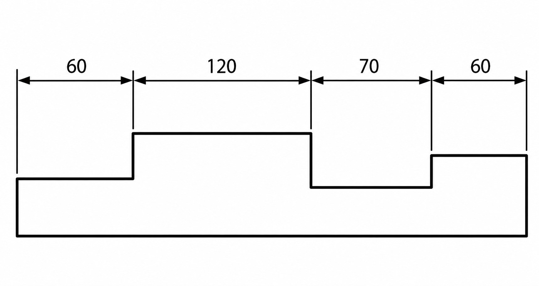
Chain Dimensioning (LibreCAD)
A linear stack-up applies when dimensions are built along a single path. Shaft assemblies, bearing arrangements, and spacer stacks commonly use this type of analysis.
A bearing location inside a housing may depend on the housing depth, bearing width, spacer thickness, and shaft shoulder position. If each dimension shifts slightly from its nominal value, the total distance changes and affects the shaft location.
Hole Pattern and Positional Tolerance Example
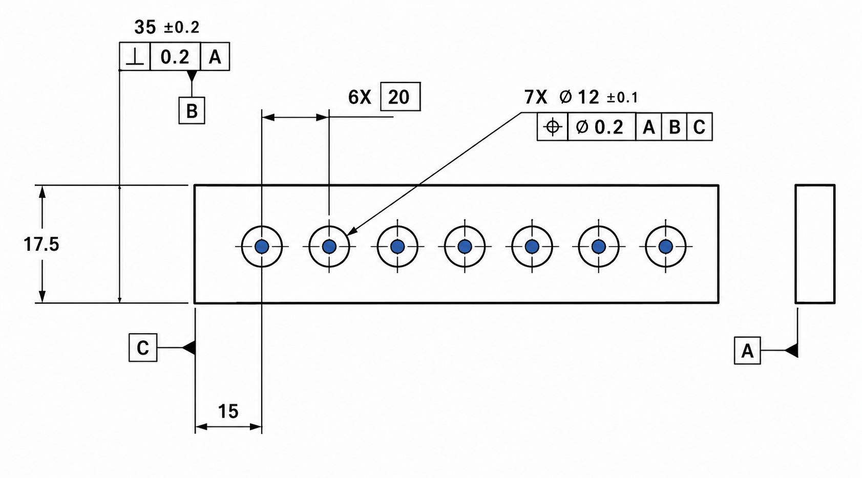
Hole pattern and positional tolerance example with GD&T callout symbols (Mechademic)
Hole pattern stack-up focuses on feature location rather than only size. It is important for parts that must match another component during assembly.
A CNC-machined flange may have four mounting holes that meet diameter requirements, but each hole can vary in position. The combined position error can affect bolt installation and the alignment between mating parts.
Multi-Part Assembly Example
Multi-part assemblies combine several tolerance sources simultaneously. Components such as gearboxes, actuators, and bearing systems depend on multiple machined features performing together.
The housing bore location, bearing seat, shaft diameter, and spacer thickness all contribute to the final assembly condition. Stack-up analysis identifies which dimensions control performance and require closer tolerance limits.
Combined Tolerance Stack-Up Examples
| Stack-Up Type | Application | Main Dimensions | Tolerance Values | Manufacturing Effect |
|---|---|---|---|---|
| Linear Dimension Chain | Shaft and bearing arrangement | Housing depth, bearing width, spacer thickness | 40.00 ± 0.05 mm, 20.00 ± 0.03 mm, 10.00 ± 0.02 mm | Total variation changes the shaft position and axial clearance |
| Hole Pattern and Position | CNC mounting flange | Hole diameter, hole spacing, hole location | Ø12.00 ± 0.05 mm, spacing 100.00 ± 0.08 mm, position tolerance Ø0.10 mm | Combined location error can affect bolt fit |
| Multi-Part Assembly | Gearbox assembly | Housing bore, bearing location, shaft size, spacer thickness | Bore location ±0.03 mm, shaft diameter ±0.02 mm, spacer ±0.02 mm | Variation affects gear alignment and operating clearance |
Tolerance Stack-Up Formulas and Calculations
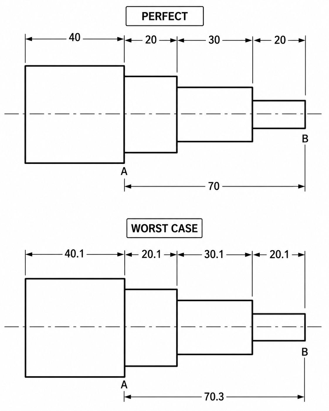
Before evaluating a stack-up result, engineers first calculate how much variation can reach the functional requirement.
The simplest approach is the worst-case calculation. It assumes every contributing dimension reaches its tolerance limit in the direction that produces the largest assembly variation.
Worst-Case Stack-Up
Total Variation = Σ|Ti|
Where:
T = individual tolerance contribution
Consider a bearing assembly where the final shaft position depends on three dimensions:
| Dimension | Tolerance |
|---|---|
| Housing Depth | ±0.05 mm |
| Bearing Width | ±0.03 mm |
| Spacer Thickness | ±0.02 mm |
The worst-case stack-up becomes:
±(0.05 + 0.03 + 0.02)
= ±0.10 mm
This means the final bearing position may shift by as much as 0.10 mm from nominal when all three dimensions move toward the same limit. Whether that amount matters depends on the application. In a loose mechanical assembly it may have little effect. In a preload-controlled bearing arrangement, the same variation can noticeably change operating conditions.
Engineers often rely on worst-case calculations when the available design margin is small. A hydraulic valve spool provides a typical example. Working clearance may be only a few hundredths of a millimeter. If dimensional variation accumulates beyond that range, spool movement can become inconsistent or excessive leakage may occur.
In production, however, dimensions rarely gather at their maximum limits simultaneously. Most measurements tend to cluster around the target value. For that reason, many engineers also evaluate stack-up using a statistical method.
RSS Formula
RSS = √(T₁² + T₂² + T₃² + ... + Tₙ²)
Using the same dimensions:
RSS
= √(0.05² + 0.03² + 0.02²)
= √(0.0025 + 0.0009 + 0.0004)
= √0.0038
≈ ±0.062 mm
The RSS result is smaller than the worst-case value because it assumes dimensional variation occurs randomly rather than accumulating at the extreme limit of every feature.
For a production run of machined housings, shafts, and spacers, RSS often provides a closer estimate of actual assembly behavior. Worst-case analysis is still preferred when assembly failure cannot be tolerated, or when the design has very little clearance available for dimensional variation.
Methods of Tolerance Stack-Up Analysis
Tolerance analysis methods (Redit)
Tolerance stack-up analysis methods are used to check how part variations combine before manufacturing and assembly. Engineers select the method based on the part function, risk level, and available manufacturing data.
Worst-Case Analysis
- Worst-case analysis adds all tolerances in the most unfavorable direction to find the maximum possible variation.
- It is used for assemblies where a small size change can cause failure, such as bearing fits, sealing gaps, and precision mechanisms.
Root Sum Square (RSS) Analysis
- RSS analysis assumes dimensions vary independently and follow a normal distribution around the target value.
- It is useful for assemblies with many dimensions where the chance of every tolerance reaching its limit at the same time is low.
Statistical Tolerance Analysis
- Statistical analysis uses measured production data to study actual part variation instead of only using drawing limits.
- It is commonly applied in higher-volume manufacturing where process capability and inspection data are available.
How to Perform a Tolerance Stack-Up Analysis
A stack-up study only works when the engineer knows what assembly condition needs control. The calculation is built around a specific requirement, not around every dimension shown on the engineering drawing.
Step 1: Define the Functional Requirement
The first task is to determine what the assembly must achieve after all parts come together. This decision defines which dimensions belong in the stack-up and which dimensions have little influence on the final result.
For instance, a bearing arrangement may depend on the total axial space between a shaft shoulder, spacer, bearing, and housing features. The stack-up calculation focuses on these contributing dimensions because they control the final clearance and operating condition.
Step 2: Identify the Dimension Chain
The dimension chain includes every feature that contributes to the final measurement. Engineers select only the dimensions that directly affect the assembly condition.
In a shaft assembly, this may include housing depth, bearing width, spacer thickness, and shaft shoulder location.
Step 3: Assign Feature Tolerances
Each dimension in the chain is assigned its drawing tolerance based on machining capability and part function.
For example, a precision bearing seat may have a tighter tolerance than a non-critical spacer because it directly affects the fit.
Step 4: Calculate Worst-Case Variation
The worst-case method adds all possible tolerance limits to find the maximum and minimum assembly condition.
If three dimensions can each vary by ±0.05 mm, the total possible variation is calculated by considering the combined effect of all three dimensions.
Step 5: Compare Results Against Design Requirements
The final stack-up result is compared with the required assembly limits. If the variation exceeds the allowed range, engineers adjust critical dimensions or modify the tolerance scheme.
This step helps identify which features need tighter control before parts enter production.
Tolerance stack-up analysis can show where assembly problems are likely to occur, but manufacturing those parts consistently is a different challenge. Features such as bearing seats or locating bores often require tighter process control than the rest of the part, while many other dimensions can remain at standard machining tolerances.
Before production begins, JLCCNC reviews engineering drawings together with the functional requirements of the assembly. If a tolerance is unnecessarily restrictive, it can often be relaxed without affecting performance. When a feature directly influences alignment or fit, the machining process and inspection method are adjusted to match that requirement.
Whether you are validating a prototype or preparing a production run, our CNC machining team can manufacture precision parts with fast lead times while maintaining the dimensional accuracy needed for reliable assembly.

Precision CNC Machining Service
Professional manufacturing, fast turnaround, and quality assurance.
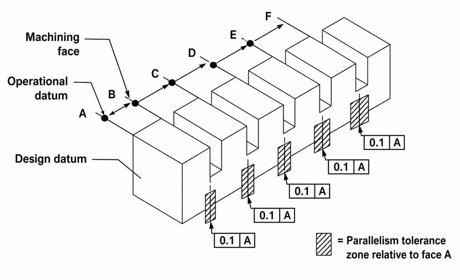
GD&T and Tolerance Stack-Up
GD&T (Geometric Dimensioning and Tolerancing) affects tolerance stack-up by controlling the relationship between part features. Geometric stack-up often involves position, orientation, and datum-related tolerances that influence feature relationships throughout an assembly. Standard dimensions control size, but many assembly issues come from feature location, orientation, or alignment.
For example, a hole may have the correct diameter but still fail assembly if its center position is outside the allowed location tolerance. GD&T defines these feature relationships using datums and geometric tolerance zones.
Datums and Dimensional Relationships
- Datums are reference features used to establish the measurement system for a part.
- A datum can be a machined surface, hole axis, or center plane selected on the drawing.
- Inspectors use the datum reference frame to measure feature locations and verify part requirements.
- In a machined housing, the base surface may locate the part, while side and hole references control the position of other features.
Position Tolerance and Feature Location
- Position tolerance controls the allowed variation of a feature from its exact theoretical location.
- It is commonly applied to holes, slots, and pins that must match another component.
- A bolt hole pattern with a position tolerance of Ø0.10 mm means each hole axis must remain inside a cylindrical tolerance zone 0.10 mm in diameter around the true location.
- This control prevents excessive location variation during assembly.
GD&T vs Traditional Plus-Minus Tolerances
- Plus-minus tolerances control individual dimensions, such as a hole diameter or distance between surfaces.
- They do not define how multiple features relate to each other.
- GD&T controls feature relationships using controls such as position, flatness, perpendicularity, and parallelism.
- For example, controlling the distance between two holes does not fully control their pattern location. A position tolerance references the complete feature location from the datums.
Using GD&T to Reduce Stack-Up Risk
- GD&T reduces tolerance chains by controlling critical features from common datum references.
- Instead of locating a hole through several chained dimensions, engineers can define its position directly from the part datum system.
- This is useful for assemblies with locating pins, bearing seats, mounting holes, and mating surfaces.
MMC and Bonus Tolerance
- Maximum Material Condition (MMC) defines the size condition where a feature contains the most material.
- For a hole, MMC is the smallest hole size. For a shaft, MMC is the largest shaft size.
- When a feature moves away from MMC, additional geometric tolerance becomes available. This additional allowance is called bonus tolerance.
- MMC is often used for mating features because it ensures assembly clearance while allowing manufacturing variation.
Factors That Increase Tolerance Stack-Up Risk
Tolerance stack-up risk increases when several dimensions and manufacturing variables influence one final assembly condition. Some designs create more variation because they include longer dimension chains, more features, or tighter functional limits.
Long Dimension Chains
- Multiple connected dimensions increase the total possible variation in an assembly.
- Each feature adds its own tolerance range to the final measurement.
- Spacer stacks, shaft assemblies, and multi-part mechanisms often require careful tolerance review.
Manufacturing Process Variation
- Machining processes create small dimensional changes due to tooling wear, machine accuracy, material movement, and setup differences.
- Separate machining operations can introduce additional variation between related features.
- Process control and inspection methods influence the measured part results.
Complex Feature Relationships
- Multiple holes, locating pins, angled surfaces, and mating faces increase the number of controlled relationships.
- A small error in feature location or alignment can affect part assembly.
- GD&T controls these relationships through datums and geometric tolerance zones.
Critical Assembly Requirements
- Assemblies with limited clearance or required alignment need tighter control of related dimensions.
- Bearing fits, gear systems, and sealing surfaces depend on accurate feature relationships.
- Critical features require proper tolerance selection to maintain the required assembly condition.
How Engineers Reduce Tolerance Stack-Up Problems
Engineers reduce tolerance stack-up by controlling the dimensions that directly affect assembly function. The goal is not to tighten every tolerance, but to manage variation at the features that influence fit, alignment, and movement.
Reducing Unnecessary Tolerance Chains
Long dimension chains increase the total variation between related features. Engineers simplify designs by removing extra reference dimensions and controlling important locations with fewer features.
A shaft position, for example, can be controlled from a main shoulder or datum instead of depending on several stacked dimensions.
Applying GD&T Effectively
GD&T controls feature relationships instead of only individual sizes. Engineers use datums, position tolerances, and orientation controls for features that must align during assembly.
A bolt hole pattern, bearing seat, or locating pin can receive direct location control from the part datum system.
Designing for Assembly
Assembly requirements should guide tolerance selection during the design stage. Engineers consider mating surfaces, required clearances, locating methods, and inspection needs before finalizing dimensions.
Parts with clear locating features usually require fewer tolerance controls during assembly.
Matching Tolerances to Process Capability
Tolerances should match the ability of the selected manufacturing process. CNC machining, grinding, casting, and forming processes produce different levels of dimensional control.
Engineers select tighter tolerances only for critical features and use wider tolerances for non-critical dimensions. This keeps the design practical for production.
Balancing Tolerance Requirements and Manufacturing Cost
Tolerance selection directly affects the machining process. A drawing with very small tolerance limits may require slower cutting conditions, additional finishing operations, and more inspection time. A wider tolerance can reduce production effort if the feature does not affect assembly or operation.
The important point is matching the tolerance to the job of the feature. A bearing bore and a cover plate surface do not require the same level of control.
The Cost of Tight Tolerances
Tight tolerances increase the amount of control needed during manufacturing. Tool wear, machine thermal changes, material movement, and setup variation become more important as tolerance limits become smaller.
A shaft diameter controlled to ±0.01 mm may require finishing operations and frequent measurement. A general mounting surface with ±0.05 mm may be completed with standard CNC machining.
Typical CNC Machining Tolerances
| Machining Operation | Common Tolerance Range | Example Feature |
|---|---|---|
| Standard CNC Milling | ±0.05 mm to ±0.10 mm | Brackets, pockets, mounting surfaces |
| CNC Turning | ±0.02 mm to ±0.05 mm | Shafts, bushings, pins |
| Precision CNC Machining | ±0.01 mm to ±0.02 mm | Bearing seats, alignment bores |
| Grinding | ±0.005 mm to ±0.01 mm | Precision fits and finishing surfaces |
Actual results depend on the machine, material, tool condition, part size, and inspection method.
Inspection and Measurement Requirements
Tolerance limits determine the inspection method. Larger tolerances can often use standard measuring tools, while smaller limits require more accurate equipment.
A critical bore may need a bore gauge or CMM inspection, while a non-critical thickness may only require a caliper or micrometer check.
When Looser Tolerances Are Acceptable
Looser tolerances are suitable for features that do not control assembly position, movement, or sealing.
Examples include non-contact surfaces, outer profiles, and clearance areas. These features can often use standard machining tolerances without affecting part performance.
Cost vs Performance Trade-Offs
Every tolerance decision involves a balance between part function and manufacturing effort.
Applying a tight tolerance to a non-critical feature increases machining and inspection work without improving the assembly. Controlling only the important dimensions gives better production efficiency while meeting design requirements.
Conclusion About Tolerance Stack-Up
Tolerance stack-up is a key part of designing parts that need to fit and work together after machining. The final assembly condition depends on many individual dimensions, not just one measurement on a drawing.
During design reviews, engineers use stack-up analysis to check conditions such as shaft movement, bearing location, gear spacing, hole alignment, and mating clearances. This helps identify critical dimensions before parts reach production.
The best approach is not assigning tight tolerances to every feature. Engineers focus control on functional surfaces, locating features, and dimensions that directly affect assembly. Other features can use normal machining tolerances to keep production practical.
Using proper stack-up analysis, GD&T controls, and suitable tolerance limits helps create parts that are easier to machine, inspect, and assemble.
For CNC machining projects that require controlled dimensions and reliable assembly results, JLCCNC provides CNC milling, turning, and custom manufacturing support for prototype and production requirements.
Upload your CAD files to get an instant CNC machining quote and DFM feedback from JLCCNC engineers.
Precision CNC Machining Service
Professional manufacturing, fast turnaround, and quality assurance.
FAQ About Tolerance Stack-Up
Q: What is tolerance stack-up?
Tolerance stack-up is the total variation created when several part dimensions work together in an assembly. It shows the possible change in fit, gap, and position after combining individual tolerances.
Q: What causes tolerance stacking?
Tolerance stacking comes from multiple dimensions contributing to one final condition. Common sources include part size variation, hole location errors, machining process limits, and differences between mating components.
Q: What is the difference between worst-case and RSS analysis?
Worst-case analysis assumes every tolerance moves in the direction that creates the largest possible variation. It is used for critical assemblies that cannot exceed a defined limit.
RSS analysis combines tolerances using a statistical method. It is commonly used when multiple dimensions have independent variation during production.
Q: How does GD&T affect tolerance stack-up?
GD&T controls the relationship between features, such as hole position, surface alignment, and part orientation. It allows engineers to control important assembly features without tightening every dimension on the drawing.
Q: Why is tolerance stack-up important in assembly design?
Individual parts can meet their drawings, but still create assembly issues when combined. Stack-up analysis checks conditions such as excessive clearance, interference, shaft movement, or feature misalignment.
Q: How can engineers reduce tolerance stack-up?
Engineers reduce stack-up by removing unnecessary dimension chains, selecting proper datums, controlling critical features with GD&T, and avoiding tight tolerances on features that do not affect assembly.
Q: Does a tighter tolerance always improve product quality?
No, a tighter tolerance only improves the feature when the function requires it. Excessive tolerance control can increase machining cost without improving assembly performance.
Q: How does tolerance stack-up affect CNC machining cost?
Small tolerance limits require more control during machining. They may need additional finishing passes, closer inspection, special tooling, or slower production settings.
Q: What is the formula for tolerance stack-up?
For a worst-case calculation:
Total stack-up = Sum of all individual tolerances
For RSS analysis:
Total stack-up = √(T₁² + T₂² + T₃² + ... + Tₙ²)
The calculation method depends on the assembly requirement and the level of variation control needed.
Keep Learning
Types of Holes in Engineering: Design, Symbols, and Manufacturing Guide
Types of holes in engineering - illustration (Erye rubber & plastic parts) Key Takeaways Engineering holes are used to support fastening, alignment, bearing installation, fluid flow, and other functional requirements. The main types of holes include through holes, blind holes, threaded holes, counterbore holes, countersink holes , spotface holes, screw clearance holes, reamed holes, and dowel holes. Hole geometry determines the required machining process. Some holes only require CNC drilling , while o......
True Position in GD&T: Symbol, Formula, Tolerance, and Manufacturing Applications
Key Takeaways About True Position True position defines the allowable variation in a feature's location from its basic dimensions. The control applies to holes, slots, pins, threaded features, and datum features. A circular tolerance zone controls features in 2D, while a cylindrical zone controls feature axes in 3D. Datum references establish the coordinate system used for manufacturing and inspection. Maximum Material Condition (MMC) adds bonus tolerance as the feature departs from its maximum materi......
Tolerance Stack-Up: Analysis, Examples, and How It Affects Manufacturing and Assembly
Key Takeaways About Tolerance Stack-Up Tolerance stack-up determines the dimensional variation that accumulates across multiple features and assembled parts. The stack-up study allows engineers to identify gaps, interference issues, alignment shifts, and fit conditions before production starts. Small dimensional variations from several parts can combine and create larger assembly issues. Usually, worst-case analysis evaluates the maximum possible variation by combining all tolerance limits. Statistica......
How to Read Engineering Drawings: Symbols, Dimensions, and Practical Interpretation
Key Takeaways About Engineering Drawings Engineering drawings communicate product requirements throughout manufacturing, inspection, assembly, and quality control. They communicate information that may not be fully defined in a CAD model, such as allowable variation, surface requirements, and inspection points. A drawing review starts with understanding the part reference system. The machinist checks which surfaces are used as datums, how features relate to each other, and which areas need access duri......
Design for Manufacturing (DFM): Principles, Guidelines, and Cost Reduction Strategies
Key Takeaways About DFM Design for manufacturing (DFM) is the process of designing products that are easier, faster, and less expensive to manufacture. Good DFM design reduces production cost long before a part reaches the factory floor. Most manufacturing costs are locked in during the design phase, not during production. Following proven design for manufacturing guidelines helps reduce machining time, material waste, tooling complexity, and assembly issues. Effective DFM improves product quality, sh......
Design for Cost in Manufacturing: DFM and Cost Reduction
Key Takeaways About Design for Cost Design for cost (DFC) integrates manufacturing cost into geometry, tolerance, material, and process decisions during early design definition. Design to cost engineering defines a target unit cost early and uses it as a design constraint alongside functional requirements. Most cost reduction potential exists during design definition, not during machining optimization or production tuning. In CNC manufacturing, cost is often driven by geometry complexity, tolerance ti......