Concentricity in GD&T: Definition, Symbol, Tolerance, and Measurement
18 min
- What Is Concentricity in GD&T?
- Concentricity Symbol and Drawing Callout
- How Does Concentricity Tolerance Work?
- Is Concentricity Still Used in GD&T?
- How Is Concentricity Measured?
- Concentricity vs Position and Runout
- Concentricity in CNC Machining
- Concentricity FAQs
- Conclusion About Concentricity
Key Takeaways
- Concentricity in legacy ASME GD&T controls the derived median points of a feature relative to a datum axis. It does not simply compare the axes of two fitted cylinders.
- Check the drawing standard first. Legacy ASME concentricity and ISO concentricity or coaxiality should not be interpreted as equivalent requirements.
- For the cylindrical example in this guide, the tolerance zone is a cylinder centered on the datum axis. The derived median points of the controlled feature must lie within this zone.
- Concentricity was removed from ASME Y14.5-2018. Existing drawings with legacy callouts must still be interpreted according to their governing standard and revision.
- Position is generally used to control feature location, while runout is used to control surface variation relative to a datum axis. The appropriate control depends on the functional requirement.
- Two shaft diameters can satisfy their size limits without satisfying the geometric relationship specified between them. On a drawing governed by an earlier ASME Y14.5 revision, concentricity may define that relationship through derived median points relative to a datum axis.
- This guide focuses on legacy ASME concentricity for cylindrical features. It explains the symbol, a worked drawing example, the tolerance zone, and inspection considerations, then distinguishes this requirement from ISO concentricity/coaxiality, position, and runout.
What Is Concentricity in GD&T?
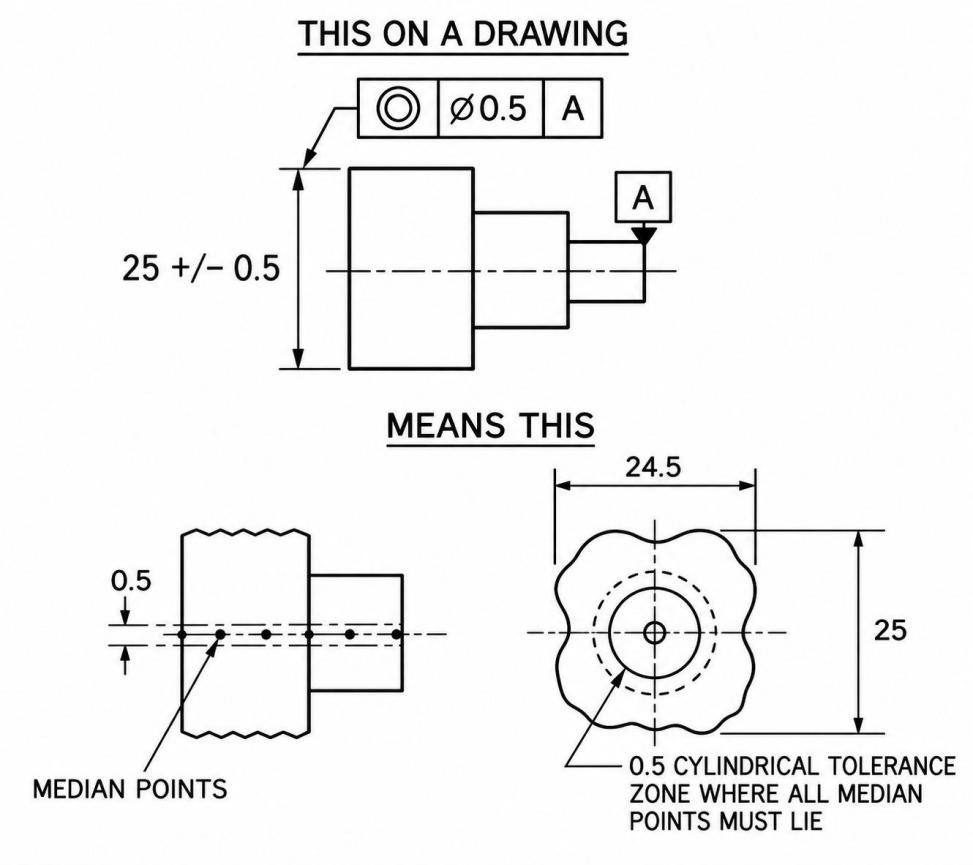
Concentricity in GD&T (emachineshop.com)
In legacy ASME GD&T, concentricity evaluates derived median points from diametrically opposed surface elements relative to a datum axis. For a cylindrical feature, these points must lie within the specified cylindrical tolerance zone centered on that axis.
A derived median point is not automatically the center of a fitted circle, and the complete evaluation is not simply a comparison between two fitted axes.
Concentricity Symbol and Drawing Callout

Concentricity Symbol (Machining Doctor)
A concentricity requirement is shown inside a feature control frame on an engineering drawing. The frame identifies the geometric control, its specified value, and the datum used as the reference. You can interpret the complete requirement by reading the frame together with its connection to the controlled feature.
Concentricity Symbol
The concentricity symbol is shown as two concentric circles:
◎
On an engineering drawing, this symbol occupies the first compartment of the feature control frame. It identifies the geometric control applied to the associated feature.
For example, a drawing may show:
◎ | ⌀0.05 | A
This callout contains three separate pieces of information. ◎ identifies the concentricity control, ⌀0.05 gives the specified tolerance, and A identifies the datum reference.
The symbol does not identify the feature by itself. You should also check the leader and the dimension associated with the feature control frame. This tells you exactly which diameter the callout controls.
How to Read a Concentricity Feature Control Frame
Read the feature control frame from left to right. Consider a stepped shaft with the larger journal identified as Datum A and a smaller journal carrying this callout:
◎ | ⌀0.05 | A
Here, the smaller journal is the controlled feature. Datum A provides the reference used by the requirement.
The diameter symbol ⌀ before the value indicates that the cylindrical tolerance zone is specified by its diameter. The value 0.05 defines the diameter of that zone. The datum letter A connects the requirement to the datum feature identified elsewhere on the drawing.
For example, if the drawing shows:
Ø30 mm – Datum A
Ø20 mm – ◎ | ⌀0.05 | A
You should not read the second callout as another size requirement for the Ø20 mm journal. The Ø20 mm dimension defines its size, while the feature control frame adds a geometric requirement relative to datum A.
This distinction helps you read drawings that contain several diameter dimensions and multiple geometric controls.
For CNC parts with a concentricity callout, the drawing requirement needs to be considered together with the datum structure, feature geometry, machining setup, and inspection method. JLCCNC can review the CAD file and technical drawing to assess the applicable GD&T requirements and recommend a suitable machining and inspection approach.

Precision CNC Machining Service
Upload your CAD file and drawing for a project-specific engineering review and quotation.
How Datum Is Used in Concentricity
The datum reference identifies the datum feature used to establish the reference for the concentricity requirement. Its letter in the feature control frame corresponds to the datum feature symbol shown elsewhere on the drawing.
For example:
◎ | ⌀0.05 | A
When a cylindrical datum feature establishes datum A, its associated datum establishes the datum axis against which the controlled feature is evaluated.
For a stepped shaft, you can trace the drawing in this order: first locate the controlled diameter, then read its feature control frame, then locate the corresponding datum feature.
Suppose the drawing identifies the Ø30 mm journal as A and places ◎ | ⌀0.05 | A beside the Ø20 mm journal. The Ø30 mm journal establishes the datum reference, while the Ø20 mm journal carries the geometric requirement.
How Does Concentricity Tolerance Work?
Concentricity evaluation is based on a set of derived median points obtained from the controlled feature at relevant cross sections. These points are evaluated relative to the datum axis.
The resulting pattern of median points must remain within the specified cylindrical tolerance zone around the datum axis. Therefore, the requirement is based on the location of these derived points rather than the outside surface of the feature itself.
Derived Median Points
A derived median point is the midpoint between a pair of diametrically opposed surface elements. Different opposed pairs within the same cross-section can produce different median points when the actual surface departs from ideal geometry.
The evaluation therefore considers a distribution of derived median points around the feature and along its controlled length. It should not be reduced to one fitted-circle center per section or a single best-fit cylinder axis.
Concentricity Tolerance Zone
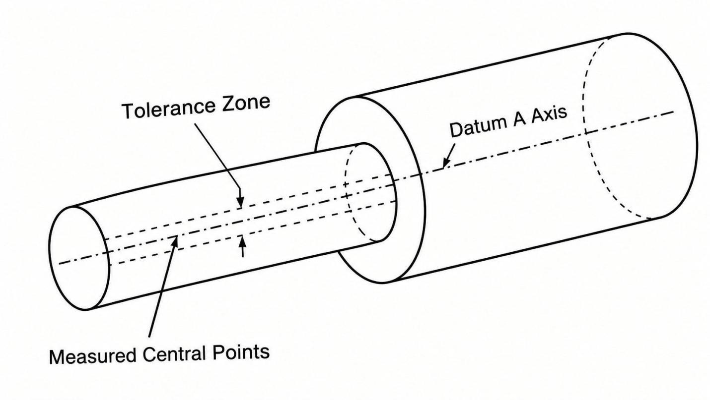
Concentricity Tolerance Zone (GD&T Basics)
The tolerance zone is a cylindrical region centered on the datum axis. Its diameter comes from the value specified in the feature control frame.
For a callout such as:
◎ | ⌀0.05 | A
The specified zone has a 0.05 mm diameter, and its axis follows the datum axis established by A.
The derived median points must remain inside this cylindrical zone. Consider a simplified cross-section: the datum axis forms the center, while the tolerance zone extends 0.025 mm from that axis in every radial direction.
The same concept applies along the length of the controlled feature. The complete set of derived median points must fit within the cylindrical zone around the datum axis.
Is Concentricity Still Used in GD&T?
Concentricity is not a supported geometric control in ASME Y14.5-2018, which remains the current ASME Y14.5 edition as reaffirmed in 2024. The 2018 revision removed both the concentricity definition and symbol, although the callout can still appear on legacy drawings created to earlier revisions.
However, you can still find concentricity callouts on existing drawings. These drawings may have been created under an earlier ASME Y14.5 revision, so the callout remains part of the drawing requirement. The drawing's applicable standard and revision should therefore be checked before interpreting the symbol.
Why Concentricity Was Removed from ASME Y14.5-2018
ASME Y14.5-2018 removed concentricity as part of the revision's changes to geometric controls. Because the requirement is based on derived median points, it can be more complex to specify, interpret, and inspect than controls that directly address feature location or surface variation.
The change does not mean that coaxial relationships can no longer be specified under ASME GD&T. Instead, the designer can use other supported controls to define the required relationship more directly.
For example, a new drawing created specifically to ASME Y14.5-2018 should not introduce a legacy concentricity frame such as:
◎ | ⌀0.05 | A
Instead, the designer should select an applicable current control based on the functional requirement. The choice depends on what the drawing must control and how the requirement is defined.
When the design intent is to control the location of a feature axis, position is generally a more direct choice. When the requirement concerns surface variation relative to a datum axis, circular runout or total runout may be more appropriate. The correct control depends on the functional requirement rather than on the desire to preserve a concentricity callout.
Why Concentricity Still Appears on Engineering Drawings
Removing a control from a newer standard does not automatically change older drawings. A component designed under an earlier revision may continue through manufacturing, inspection, maintenance, and replacement cycles with its original drawing unchanged.
For example, an older drawing may contain:
◎ | ⌀0.05 | A
If the title block identifies an earlier ASME Y14.5 revision, the concentricity callout should be interpreted according to the standard referenced by that drawing.
This distinction is important during drawing review. A legacy callout should not be removed simply because it is absent from Y14.5-2018. First, check the drawing's general notes, title block, specification references, and revision history.
A manufacturing team may also receive older drawings from customers that remain active for production. In that case, the existing specification governs the inspection requirement unless the customer issues a revised drawing.
Concentricity vs Coaxiality: ASME and ISO
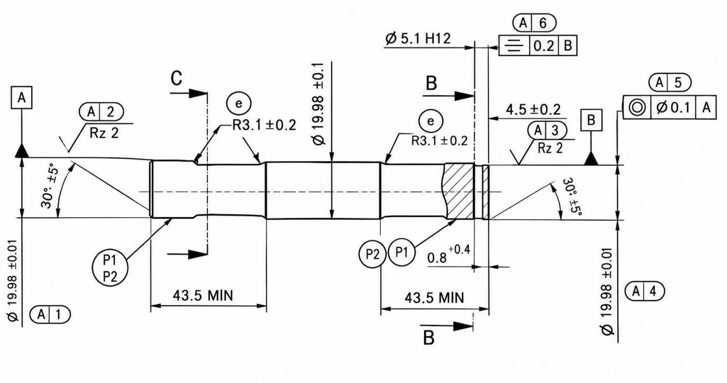
Concentricity vs Coaxiality (ZEISS Quality Forum)
Legacy ASME Y14.5 concentricity controls derived median points relative to a datum axis. ISO 1101:2017 distinguishes between concentricity and coaxiality: concentricity applies to centre points, while coaxiality applies to a median line or axis. The two standards therefore should not be treated as using concentricity and coaxiality as direct one-to-one equivalents.
This distinction matters when interpreting international drawings because the same-looking symbol does not necessarily represent the same geometric requirement under ASME and ISO rules. The referenced standard should be identified before determining the toleranced feature and evaluation method.
ISO 1101:2017 defines the symbol language and rules used for geometrical specification and interpretation. Therefore, the standard referenced by the drawing should always be identified before applying the terminology or evaluation method.
In practice, keep three cases separate: current ASME Y14.5-2018 requirements, legacy ASME drawings, and ISO GPS drawings. Always identify the governing standard before interpreting the symbol, toleranced feature, and evaluation method. This prevents an older concentricity symbol from being treated as a current ASME control without checking the governing specification.
How Is Concentricity Measured?
When a drawing contains a legacy concentricity requirement, inspection begins by establishing the datum axis identified in the feature control frame. The controlled feature is then measured at multiple sections to derive the median points used for evaluation.
For a cylindrical feature, measurement data from diametrically opposed surface elements can be used to establish derived median points at relevant cross sections. These points are evaluated relative to the datum axis and the specified cylindrical tolerance zone.
For example, suppose the drawing specifies:
◎ | ⌀0.05 | A
The derived median points must remain within a cylindrical tolerance zone with a diameter of 0.05 mm, centered on the datum axis established by datum A. If the required median-point pattern remains within the zone, the feature satisfies the concentricity requirement.
Why Concentricity Is Difficult to Inspect
Concentricity is more complex than checking whether two nominal center locations line up. The evaluation is based on the derived median points of the controlled feature rather than simply comparing the centers of two measured circles.
Consider a stepped shaft with the larger journal identified as Datum A and the smaller journal carrying:
◎ | ⌀0.05 | A
The inspection must first establish the datum axis from the larger journal. Data from the smaller journal is then collected at suitable cross sections to determine its derived median points.
A single cross-section provides the center information at only one location and does not describe the complete feature. The derived median points can vary along the length of the controlled feature, so the inspection must sample the feature sufficiently to characterize the resulting pattern relative to the datum axis.
Surface form can also affect the measured center at each section. Simply checking two nominal center locations therefore does not provide the same evaluation as the legacy concentricity requirement.
Measuring Concentricity with a CMM
A CMM can establish the datum reference and collect coordinate data from the controlled feature. The process begins by measuring the datum feature and establishing the applicable datum reference. For a cylindrical datum feature, the applicable datum reference establishes the datum axis used for evaluation.
The CMM can then measure the controlled cylindrical feature at multiple sections and collect the coordinate data needed to derive the median-point pattern. The collected data is used to determine the derived median points, which are evaluated relative to the datum axis and the specified tolerance zone.
For example, consider the following drawing requirement:
Datum A: Ø30 mm
Controlled feature: Ø20 mm
Callout: ◎ | ⌀0.05 | A
The CMM first establishes the axis from the Ø30 mm datum feature. It then collects data from the Ø20 mm feature along its length to determine the derived median points.
If the resulting median-point pattern remains within the specified ⌀0.05 mm cylindrical zone around the datum axis, the feature satisfies the stated concentricity requirement. If the required point pattern extends outside the zone, the feature fails the requirement.
The inspection result depends on both the datum reference and the feature data used for evaluation. A CMM is a common approach because it can provide coordinate data for deriving the median-point pattern, but the inspection method should be selected according to the drawing requirement, feature geometry, and available measurement capability.
Concentricity vs Position and Runout
Concentricity, position, and circular runout address different drawing requirements even though they can appear on similar cylindrical features. The key difference is what the drawing intends to control.
A legacy concentricity callout evaluates derived median points relative to a datum axis. Position controls the location of a feature's axis or center plane relative to its theoretically exact location established by basic dimensions and the applicable datum reference frame. Circular runout controls surface variation at individual cross sections relative to a datum axis.
For a cylindrical feature, choosing the control based on the required function gives the drawing a clearer inspection requirement.
Concentricity vs Position
Concentricity uses derived median points to control the relationship between a feature and a datum axis. Position instead defines where the feature's axis is allowed to lie relative to its theoretically exact location.
Consider a cylindrical hole whose location is defined from a datum reference frame using basic dimensions. If the functional requirement is to control where the hole axis lies relative to those datums, a position tolerance is generally more direct. A typical feature control frame may reference datums such as:
⌄ | ⌀0.05 | A | B | C
The applicable datum sequence depends on how the feature location is established on the drawing.
A concentricity callout such as:
◎ | ⌀0.05 | A
serves a different purpose. It relates the derived median points of the controlled feature to datum A.
Therefore, position is generally a more direct choice when a current ASME drawing needs to control the location of a cylindrical feature axis.
Concentricity vs Circular Runout
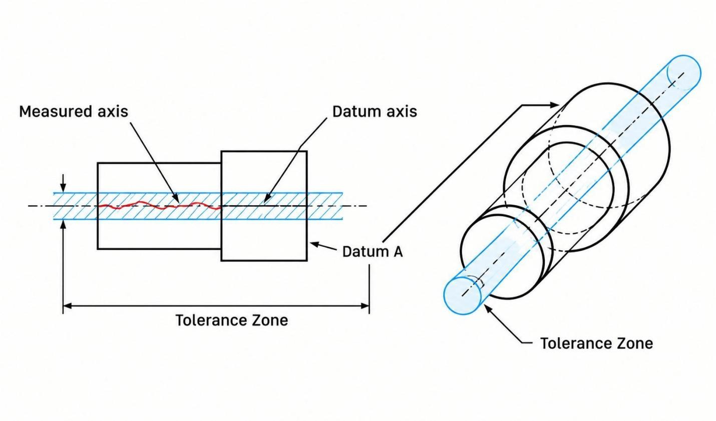
Concentricity vs Runout (Molded Dimensions Group)
Circular runout focuses on the variation of a surface as the part rotates about its datum axis. A typical callout may appear as:
↗ | 0.03 | A
The controlled surface is checked at individual circular sections relative to datum axis A. The requirement, therefore, addresses the surface's radial variation at those sections.
A legacy concentricity callout:
◎ | ⌀0.05 | A
uses derived median points instead. The evaluation is therefore based on a different feature characteristic.
For example, a rotating shaft journal may have a requirement related to how much its surface moves relative to a datum axis during rotation. Circular runout provides a direct way to express that requirement.
Thus, runout is generally more appropriate when the functional requirement concerns surface variation relative to a datum axis.
When Is Position or Runout a Better Choice?
Position is generally more suitable when the drawing must control the location of a feature from established datums. This is common for holes, bores, and other features whose location affects assembly.
Circular runout is better suited to a rotating surface where surface variation relative to a datum axis must be controlled. This makes the requirement directly connected to the surface characteristic being inspected.
For example, consider a rotating shaft with a bearing journal. If the drawing mainly controls the journal's location relative to the datum reference, a position tolerance can express that requirement more directly. If the requirement concerns radial surface variation during rotation, circular runout provides more direct control.
Concentricity may still appear on an older drawing, but it should not automatically be carried into a new ASME Y14.5-2018 drawing. First, identify the functional requirement, then select the supported GD&T control that expresses it clearly.
The practical rule is simple: use position for feature location, runout for rotational surface variation, and treat concentricity callouts according to the standard governing the drawing.
Concentricity in CNC Machining
A concentricity callout can change the way a CNC part is set up and inspected. Consider a stepped shaft: the larger diameter establishes datum A, while a smaller journal has a concentricity requirement to A. The machining process has to maintain the dimensional and geometric relationship that will later be evaluated from datum A.
This is different from checking whether two diameters look centered. Concentricity uses derived median points from the controlled feature, so measurements at several sections along the journal can reveal a shift that a simple diameter check would miss.
Where Concentricity Requirements Appear in CNC Parts
Legacy concentricity requirements are commonly encountered on stepped shafts, sleeves, and other precision parts with cylindrical features that share a functional axis. A typical drawing may use one diameter as datum A and apply a concentricity tolerance to another diameter.
The important manufacturing point is the datum relationship. The controlled feature is not compared with another nominal diameter; its derived median is evaluated from the datum axis.
Machining Considerations for Tight Concentricity
For a stepped shaft, maintaining the related diameters from a common machining axis can reduce the risk of introducing positional error between setups. When the design allows it, machining multiple coaxial features in the same setup can improve axis-to-axis consistency because the features do not depend on re-establishing the relationship after a setup change. If the smaller journal is machined after a setup change, the new locating method becomes critical because the controlled feature still has to relate to datum A.
On turned parts, coaxial diameters are commonly produced by machining multiple features from a common spindle axis or by controlling the relationship through the chosen workholding strategy. For bored or reamed features, the machine setup, tool alignment, and datum transfer can similarly affect the resulting axis relationship. The manufacturing process should therefore be planned around the drawing datum structure rather than around nominal diameter values alone.
Inspection should use that same relationship. A CMM establishes the datum axis, measures the controlled diameter at multiple sections, derives the median points, and checks them against the cylindrical tolerance zone.
Concentricity FAQs
Q: What Is the Difference Between Concentricity and Coaxiality?
The terms are related but are not interchangeable across standards. In legacy ASME Y14.5, concentricity evaluates derived median points relative to a datum axis. ISO 1101 distinguishes concentricity, which applies to centre points, from coaxiality, which applies to a median line or axis. The governing standard should therefore be identified before interpreting the requirement.
Q: Is Concentricity a Form or Location Tolerance?
In legacy ASME Y14.5, concentricity is a location control rather than a form control. It establishes the relationship of a feature's derived median points to a datum axis. Its evaluation depends on the feature and datum relationship rather than controlling the surface form by itself.
Q: What Features Can Concentricity Control?
In legacy ASME GD&T, concentricity is generally applied to cylindrical or other surfaces of revolution where the relationship of derived median points to a datum axis is a design concern. Common examples include journals, stepped shaft diameters, and cylindrical features on sleeves and rotating components.
Q: What Should You Do When a Legacy Drawing Specifies Concentricity?
First, check the drawing revision and the GD&T standard it references. Concentricity was removed from ASME Y14.5-2018, but older drawings can still contain the callout. Do not replace the requirement based only on the current standard; interpret the drawing according to its governing revision and specification.
Precision CNC Machining Service
Professional manufacturing, fast turnaround, and quality assurance.
Conclusion About Concentricity
Concentricity in legacy ASME GD&T evaluates the derived median points of a feature relative to a datum axis within a cylindrical tolerance zone. It differs from position and runout because those controls address different geometric characteristics and functional requirements.
For legacy drawings, the applicable ASME revision or other governing standard should be confirmed before interpreting a concentricity callout. For CNC parts with concentricity, position, runout, or other GD&T requirements, upload the CAD file and drawing to JLCCNC for a project-specific machining review and quotation.
Keep Learning
Circularity GD&T Explained
Key Takeaways Circularity controls how round each cross-section is on a cylindrical, conical, or spherical surface. Each cross-section is checked separately. Circularity doesn't control taper, axis straightness, or alignment between sections. No datum is needed because circularity controls the shape of the feature itself. The circularity tolerance zone is bounded by two concentric circles whose radial separation equals the specified tolerance. Each circular element must fit within its own zone, evalua......
Press Fit Tolerance: Interference, Charts & Design Guide
Key Takeaways A press fit is an interference fit: the shaft is larger than the hole, and elastic deformation of the mating parts after assembly creates contact pressure that generates the friction holding the joint together. Press fit interference is the difference between the shaft diameter and the hole diameter. Minimum interference uses worst-case dimensions for the smallest overlap. Maximum interference uses worst-case dimensions for the largest overlap. Press fit tolerance is selected based on re......
GD&T Datum: Definition, Types, Symbols, and Datum Reference Frame
Key Takeaways A datum in GD&T is a theoretically exact reference used to locate or orient other features on a part. It is not the physical surface itself. A datum feature is the physical feature identified on the part and used to establish a datum. The datum itself is the theoretically exact geometric reference derived from that feature. Datums become especially important when several features have to work together. A hole pattern, bearing bore, mounting face, or mating surface may need to establish t......
GD&T Runout: Definition, Symbol, Measurement & Tolerance
Key Takeaways Runout limits surface variation while a part rotates around its specified datum axis. The datum feature establishes the axis used for the runout requirement. You compare the full indicator variation during rotation with the tolerance stated on the drawing. Circular runout applies at individual circular sections of the controlled surface. Total runout evaluates the controlled surface across its specified extent. Runout is not a size tolerance, and its value is not determined by the diamet......
GD&T Perpendicularity: Definition, Tolerance & Examples
Key Takeaways Perpendicularity is an orientation control used for a feature specified at 90° to a datum. A surface callout controls the complete surface within two parallel planes set perpendicular to the referenced datum. An axis callout controls the derived axis inside the specified tolerance zone instead of controlling the physical surface directly. Perpendicularity does not establish the location of a feature. A drawing can require another geometric control when position also needs definition. Dat......
Concentricity in GD&T: Definition, Symbol, Tolerance, and Measurement
Key Takeaways Concentricity in legacy ASME GD&T controls the derived median points of a feature relative to a datum axis. It does not simply compare the axes of two fitted cylinders. Check the drawing standard first. Legacy ASME concentricity and ISO concentricity or coaxiality should not be interpreted as equivalent requirements. For the cylindrical example in this guide, the tolerance zone is a cylinder centered on the datum axis. The derived median points of the controlled feature must lie within t......