CMM Inspection: Measurement, Process & Quality Control
9 min
- What Is CMM Inspection?
- Types of CMM Machines
- How Does CMM Inspection Work?
- CMM Inspection in CNC Manufacturing
- CMM Inspection and Quality Control
- CMM Inspection Reports and Traceability
- When Is CMM Inspection Needed?
- CMM vs Other Inspection Methods
- What Affects CMM Inspection Accuracy?
- CMM Inspection FAQs
- Conclusion About CMM Inspection
Key Takeaways
- CMMs measure the three-dimensional coordinates of part features within a defined coordinate system.
- Datum alignment and probing strategy determine how the part is interpreted and which characteristics can be evaluated.
- CMMs are especially useful for GD&T relationships, complex geometry, and tight tolerances that are difficult to verify with basic gauges.
- Fixturing, temperature, probe access, and measurement uncertainty all affect the confidence of the inspection result.
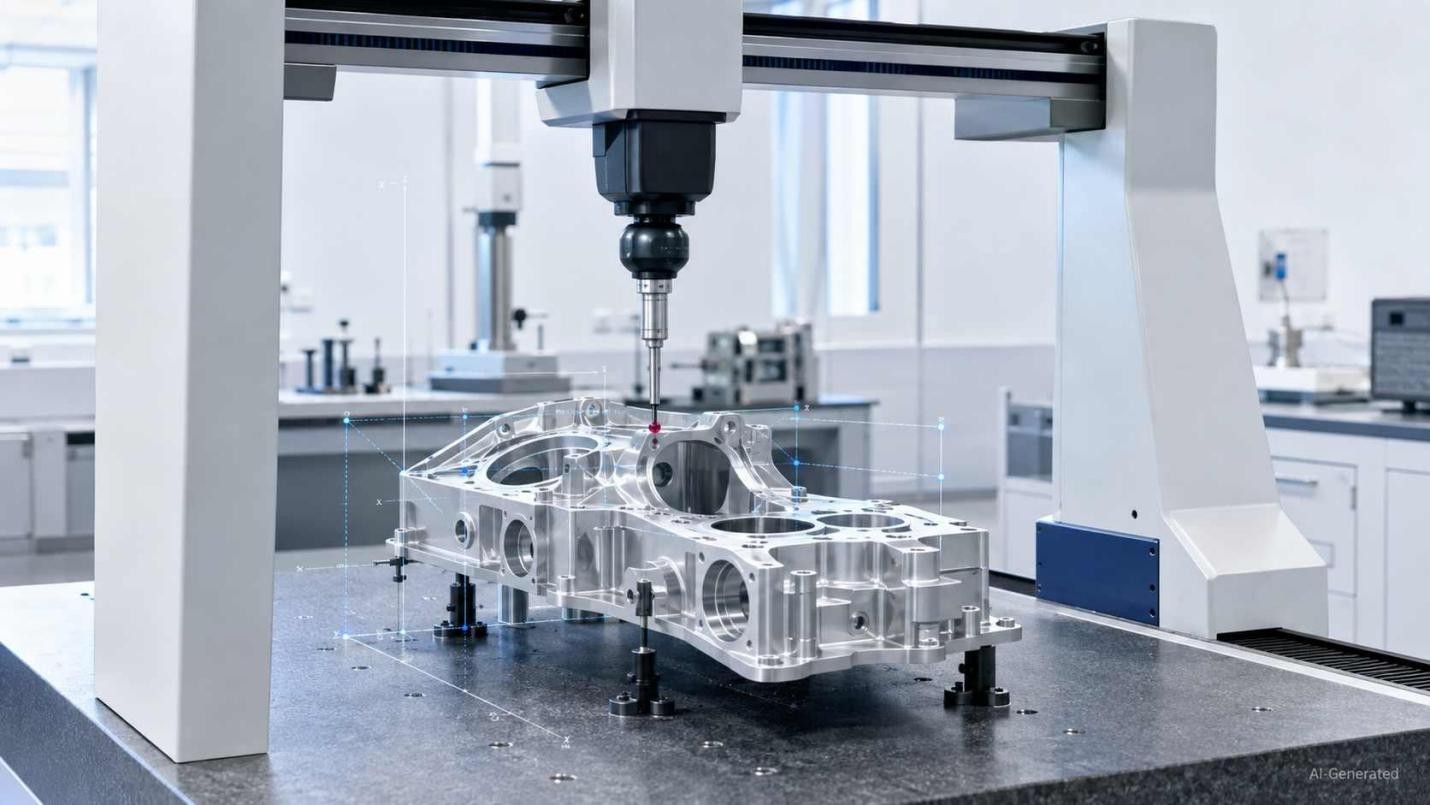
Bridge CMM inspecting a CNC-machined aluminum part
CMM inspection verifies whether measured part geometry conforms to the applicable drawing and GD&T requirements. CMM measurement supplies dimensional evidence. CMM measurement provides dimensional and geometric evidence that can be evaluated against drawing requirements, CAD nominal geometry, and GD&T specifications.
What Is CMM Inspection?
CMM inspection is a dimensional verification process that uses a coordinate measuring machine to measure the location and geometry of part features relative to a defined coordinate system. The measured results are evaluated against engineering drawings, CAD nominal geometry, GD&T requirements, or other specified tolerances.
Types of CMM Machines
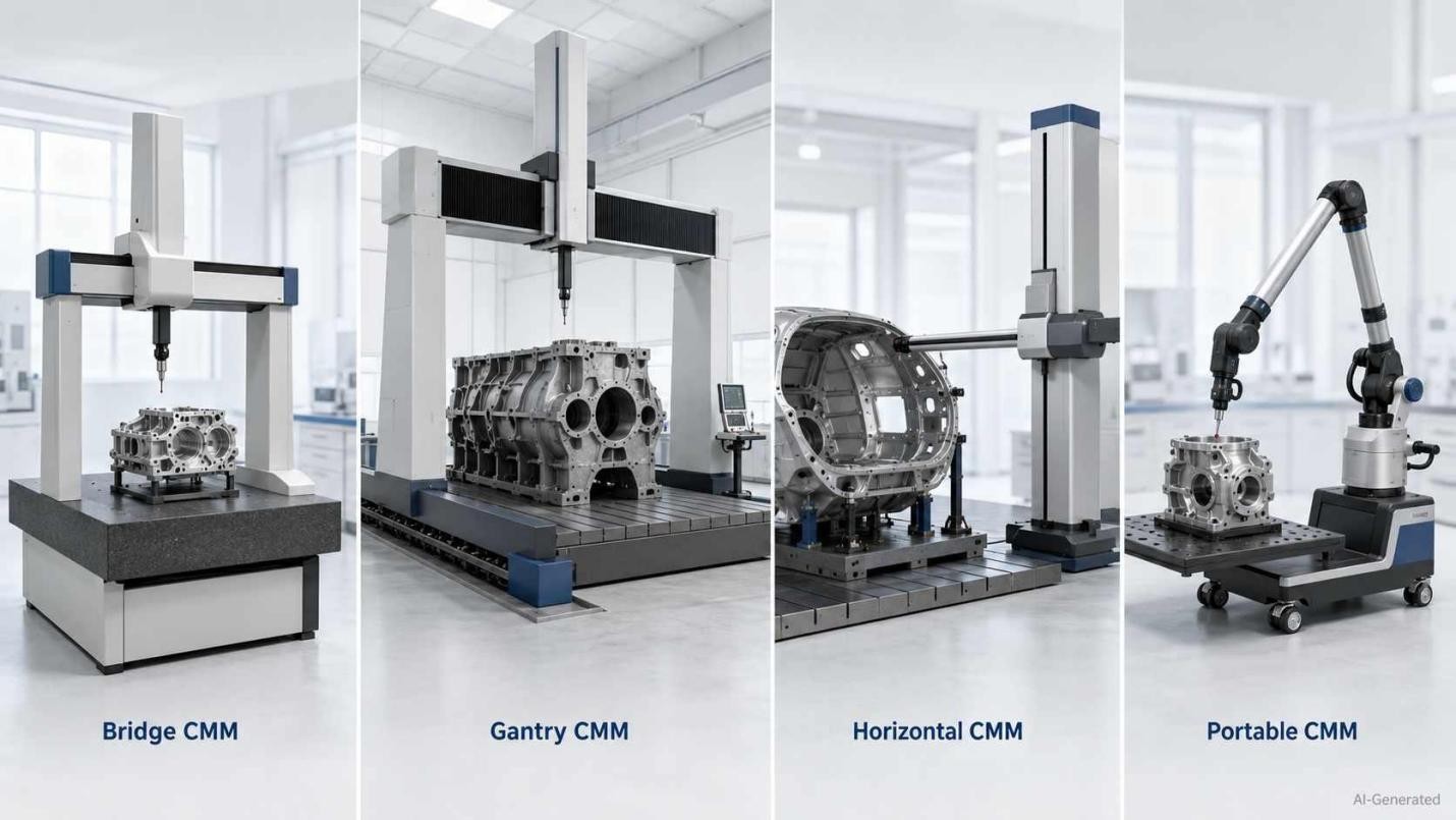
Bridge, gantry, horizontal, and portable CMM machines
Bridge CMM
A bridge CMM carries its probe along three Cartesian axes above a stationary table. Its rigid structure and fixed measuring volume make it well suited to repeatable inspection of precision machined parts in a controlled metrology environment.
Gantry and Horizontal CMM
Gantry CMMs provide a much larger measuring volume for oversized parts, fixtures, and assemblies that cannot be accommodated on a conventional bridge CMM. A horizontal arm reaches side-facing areas on vehicle bodies and long assemblies. These arrangements allow open loading and broad reach when a bridge layout lacks capacity.
Portable CMM
Portable measurement systems include articulated-arm CMMs and laser trackers. They are useful when a large component cannot be moved easily into a dedicated metrology lab. Their measurement capability is strongly affected by setup, operator technique, temperature, line of sight, and the specific system configuration.
How Does CMM Inspection Work?
Part Setup and Datum Alignment
CMM inspection secures the component without distortion and locates the specified primary, secondary, and tertiary datum features. Their precedence sets the origin, axis directions, and rotational orientation of the part coordinate system as per the drawing's datum reference frame.
Probing and Feature Measurement
Using a CMM in manufacturing implies choosing a sensor for the task. Touch-trigger probes capture discrete points. Tactile scanners follow continuous paths. Touch-trigger probes capture discrete points, while scanning probes collect continuous measurement data along a defined path. Optical sensors can capture surface data without physical contact.
Data Analysis and Inspection Reporting
Metrology software calculates geometric characteristics and nominal-to-actual deviation. It checks each value against its tolerance zone. The final document lists acceptance status, job and serial numbers, and traceability details for production release or corrective action.
CMM Inspection in CNC Manufacturing
Verifying CNC Machined Part Accuracy
During first-off, in-process, or final verification, CMM measurement determines whether a machined component conforms to the applicable drawing requirements, dimensional tolerances, GD&T callouts, and customer inspection criteria. The outcome can authorize the batch, identify an incorrect machine offset, or hold a nonconforming item before the next operation.
Inspecting Tight Tolerances and Complex Geometry
Whenever tolerances narrow or geometry is challenging, CMM testing assesses compound angles, deep bores, hole patterns, freeform contours, and relationships among surfaces and axes in a single setup. Engineers concentrate coverage on mating interfaces and function-critical areas. Even a slight deviation could compromise assembly or performance.
For example, a mounting plate may have four holes with a position tolerance referenced to three datums. Measuring the hole diameter alone does not verify the position requirement. The CMM routine must establish the specified datum reference frame, measure the hole axes, and evaluate their location within the applicable tolerance zone.

Precision CNC Machining Service
Effective CMM inspection goes beyond collecting coordinates. For CNC parts with tight tolerances or complex GD&T requirements, JLCCNC can review the drawing and determine the appropriate inspection approach during the manufacturing process.
CMM Inspection and Quality Control
Verifying Conformance to Engineering Drawings
CMM inspection links each characteristic to the released engineering drawing, nominal value, tolerance, datum structure, and applicable material-condition modifiers. Conformity follows the stated acceptance rule. Geometric proximity to a CAD surface is insufficient.
Detecting Dimensional Variation
Across a sequence of parts, CMM quality control shows drift, spread, or location-specific patterns that an isolated acceptance decision can hide. Through the process of sorting readings according to machine, cutter, cavity, or batch, it is possible to uncover progressive wear, thermal movement, and process alterations before the output crosses a specification boundary.
CMM Inspection Reports and Traceability
The retained record links the values that were observed to the revision of the source drawing, the routine version, the calibration reference, the date, and the disposition. This audit trail supports customer submissions, repeat-order comparisons, nonconformance investigations, and contractual retention duties.
When Is CMM Inspection Needed?
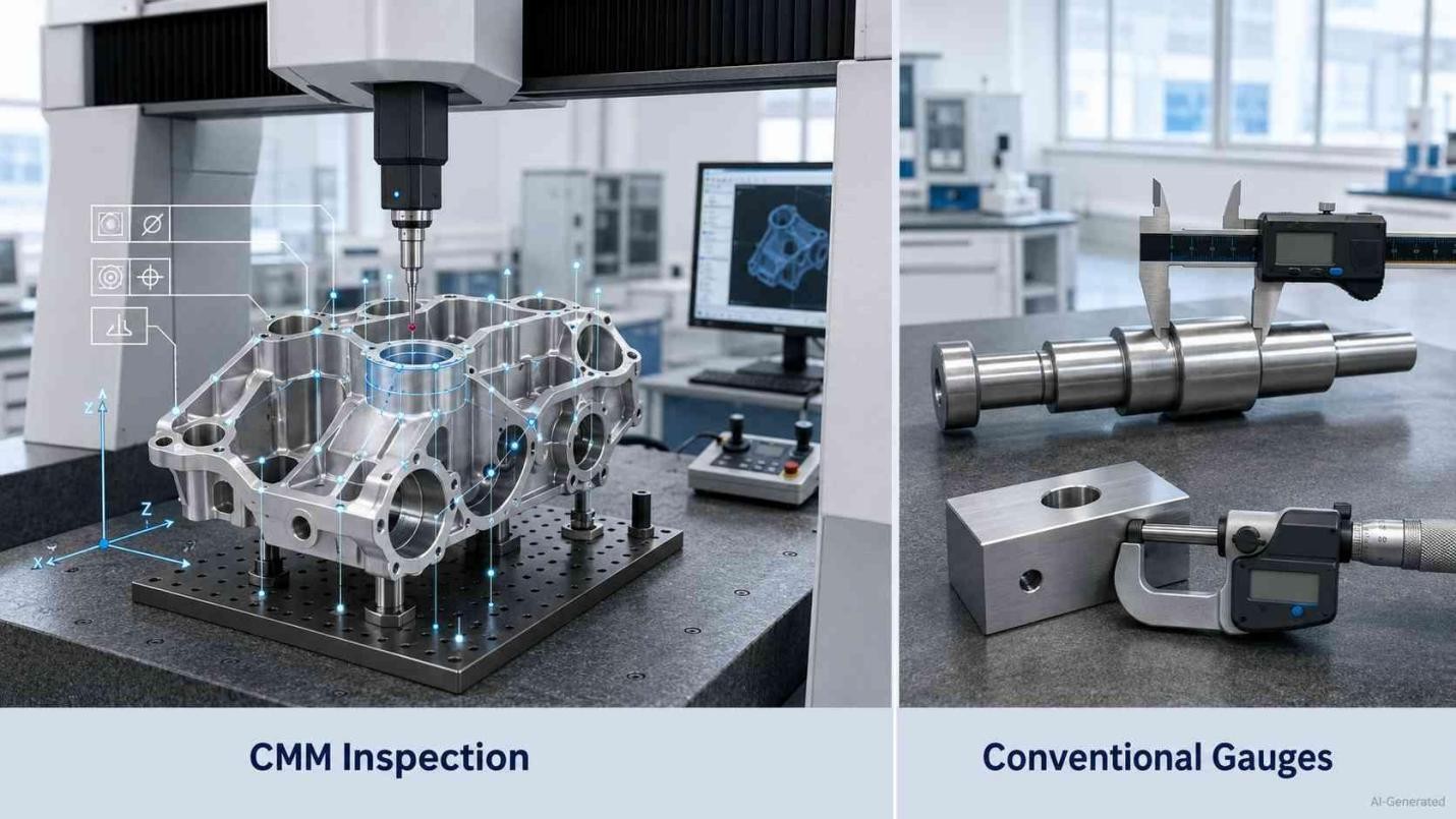
CMM inspection versus calipers and micrometers
Complex Features and GD&T Requirements
CMM inspection is appropriate when a requirement cannot be isolated from the rest of the component. For example, a bolt-circle location referenced to three datums may require CMM inspection because the characteristic depends on their spatial relationship. It is suitable for tasks that need quantifiable proof for each GD&T feature rather than a conclusion that is just based on attributes.
Tight Tolerances and Critical Features
Tolerance severity introduces another decision point. CMM measurement is justified only when task-specific uncertainty leaves enough margin for a defensible acceptance decision. Typical candidates include bearing-seat relationships, sealing interfaces, alignment bores, and dimensions whose failure could affect assembly, motion, or safety. CMM capability should be considered together with the measurement uncertainty of the specific inspection task, not from machine accuracy alone.
When Conventional Gauges Are Sufficient
Conventional tools are sufficient for accessible and independent dimensions whose tolerance matches the instrument's capability. Examples include thickness, outside diameter, slot width, and thread acceptance. A calibrated micrometer, caliper, height gauge, pin, or go/no-go device is more efficient when no spatial relationship or formal data package is needed.
CMM vs Other Inspection Methods
| Method | Measurement approach | Suitable applications | Information produced | Primary constraint |
|---|---|---|---|---|
| Coordinate measuring machine (CMM) | A tactile stylus records discrete points or traces continuous paths along three axes. | Datum-based GD&T, interrelated 3D geometry, precision characteristics, and customer verification. | Numerical dimensions and geometric evaluations. | Needs part restraint, probe access, programming, and stable surroundings. |
| Vision measuring machine (VMM) | A camera detects edges and visible boundaries without touching the component. | Thin or delicate items, close hole spacing, sharp edges, and 2D geometry. | Image-derived coordinates and dimensional values. | Depends on line of sight, lighting, contrast, and edge definition. |
| Structured-light or laser scanner | Projected light gathers a dense point cloud across exposed areas. | Freeform surfaces, castings, sheet metal, and broad CAD deviation studies. | Point clouds, meshes, and color-coded deviation plots. | Occlusion, reflectivity, translucency, and calibration can affect uncertainty. |
| Micrometer, caliper, or height gauge | Direct contact provides an individual reading from accessible faces. | Outside diameters, thicknesses, widths, depths, and step heights. | One numerical value per check, entered manually. | Limited coverage of multi-axis relationships and advanced GD&T. |
| Functional or go/no-go gauge | A physical boundary tests whether a feature is within its permitted envelope. | Repeated production checks for size, maximum material condition, or virtual condition. | Attribute acceptance or rejection. | Reveals no actual deviation and demands dedicated tooling. |
What Affects CMM Inspection Accuracy?
Part Fixturing and Measurement Stability
CMM inspection begins with restraint that avoids motion under probing force without having to bend thin walls or alter the required inspection state. Support locations and clamp loads must be steady throughout the run. Any slip or flex changes the geometry presented to the machine.
Probe Access and Measurement Strategy
After securing a workpiece, confidence in CMM measurement depends on unobstructed targets, a rigid stylus, and approach paths near the surface normal. Point count and spatial distribution must represent the intended characteristic. Sparse or clustered samples can overlook form error.
Temperature, Calibration, and Measurement Conditions
ISO 1:2022 defines 20 °C as the standard reference temperature for the specification and verification of geometrical and dimensional properties. Remember, differences among the CMM, component, and air can change results through thermal expansion. Gradients, vibration, airflow, dust, and sunlight further disturb consistency. Routine calibration and interim checks monitor drift. Acceptance and reverification tests under the applicable part of ISO 10360 assess performance against stated maximum permissible errors.
CMM Inspection FAQs
What Is CMM Inspection?
CMM inspection compares measured part geometry with the applicable dimensional and geometric requirements and records the resulting conformity decision.
What Is a Coordinate Measuring Machine?
The equipment behind this task is a programmable metrology system. It records surface points within a coordinate frame through tactile, imaging, or combined sensing.
What Does CMM Measure?
Using those coordinates, it calculates size, location, orientation, and form. Diameter, distance, angle, flatness, roundness, straightness, and sphericity are all included.
How Is CMM Used in Manufacturing?
Across production, teams apply the technology to first-article approval, setup validation, in-process checks, final acceptance, tooling assessment, and capability studies.
Is CMM Inspection Required for Every CNC Machined Part?
No. Whether CMM inspection is required depends on the drawing, customer requirements, inspection plan, and risk associated with the characteristic.
What Is a CMM Inspection Report?
The resulting record connects each characteristic ID with its nominal value, observed result, deviation, tolerance, and pass-or-fail status, alongside part and program identifiers.
What Is the Difference Between CMM and VMM?
For comparison, a CMM contacts three-dimensional surfaces with a stylus. A VMM makes use of camera imagery and edge detection for non-contact measurement, generally on small or planar details. Imaging-probe machines create some overlap.
Conclusion About CMM Inspection
Effective CMM inspection goes beyond collecting coordinates. It's valuable if it aligns verification with design intent, production risk, and required evidence. The inspection method should provide enough evidence for the specified tolerance without adding measurement steps that do not affect the acceptance decision. For your next precision project, explore JLCCNC CNC machining capabilities.
Precision CNC Machining Service
Upload your CAD file and engineering drawing for CNC machining review and inspection requirements. JLCCNC can evaluate part geometry, tolerance requirements, GD&T callouts, and suitable inspection methods before production.
Keep Learning
What Are Secondary Operations in Manufacturing?
Key Takeaways Secondary operations refine a part after its main production stage. Their classification depends on the production route. Typical tasks include machining, heat treatment, finishing, joining, and marking. Final drawing requirements help determine which added steps are needed. Extra stages can influence cost, lead time, handling, and inspection. Secondary operations are additional manufacturing steps performed after an earlier production stage to bring a part to its required final conditio......
What Is EDM? How Electrical Discharge Machining Works
What Is EDM (Electrical Discharge Machining)? How It Works & Applications A mold shop needs to cut a cavity into hardened tool steel — the kind of material that would dull a carbide end mill before the cut is even halfway done. A medical device maker needs a slot 0.05mm wide in a titanium component, thinner than most drill bits can even produce. Neither job is solvable with a spinning cutting tool, because the material is either too hard, the geometry too fine, or both. That's the gap EDM was built to......
Wire EDM Machine: Types, Specs & How to Choose One
Wire EDM Machine: Types, Specs & How to Choose One Our guide on how EDM wire cutting works covers the process itself — the spark erosion, the dielectric fluid, the tolerances the technique can hold. This one is about the machine that runs that process: what actually differentiates one wire EDM machine from another, and what matters when you're evaluating or specifying one. 💡 Need Precision Wire EDM Services? Understanding machine specs is crucial, but actually running them takes experience. At JLCCNC......
Titanium CNC Machining: Properties, Challenges & Best Practices
Titanium CNC Machining: Properties, Challenges & Best Practices A shop that's comfortable machining aluminum all day can still get caught off guard the first time a titanium job comes through. The part looks the same on the CAD screen, the toolpath strategy looks reasonable, and then the tool overheats, work-hardens the surface it just cut, and the finish comes out nothing like what aluminum would have produced at the same settings. Titanium isn't just "harder aluminum" — it behaves differently enough......
High Volume CNC Machining: What Changes When You Scale Production
High Volume CNC Machining: What Changes When You Scale Production Ten prototypes and ten thousand production parts are not the same problem wearing different clothes. A process that works fine for a handful of pieces — a bit of manual deburring here, a quick visual check there, tooling that gets swapped whenever it feels a little dull — falls apart the moment volume multiplies by a thousand. High volume CNC machining isn't just "the same thing, more of it." It's a different set of priorities, where de......
PTFE CNC Machining: Properties, Applications & Best Practices
PTFE CNC Machining: Properties, Applications & Best Practices PTFE — better known by the DuPont trade name Teflon — is a strange material to put on a CNC machine. It's soft, it barely holds a sharp edge itself, and it deforms under clamping pressure in ways that would ruin tolerance on almost any other engineering plastic. And yet it gets machined constantly, because nothing else offers PTFE's combination of an almost unbelievably low coefficient of friction and near-universal chemical resistance. Mac......