Lead Angle: Definition, Formula, and Applications
9 min
- What Is a Lead Angle?
- How to Calculate Lead Angle
- Lead Angle vs. Helix Angle: What Is the Difference?
- How Does Lead Angle Affect Mechanical Performance?
- Lead Angle Considerations in CNC Thread Machining
- FAQs About Lead Angle
Key Takeaways
- The lead angle is the angle between a thread's helical path at the pitch diameter and a plane perpendicular to the thread axis.
- It is calculated based on the pitch diameter and thread lead.
- For a given thread pitch, more starts increase the axial travel per revolution.
- Lead and helix angles are different according to their reference directions.
- Thread geometry affects transmission efficiency and resistance to backdriving.
- In CNC thread turning, the insert inclination must be set correctly to maintain flank clearance.
Lead angle diagram with threaded screw and worm gear
A screw does more than fasten two components together. It can raise a load, convert rotary motion into linear motion, or transmit rotation between shafts. The lead angle influences how these mechanisms move and respond to applied loads. But how smoothly? What controls if a mechanism is free or is there resistance to driving it backwards? Much of its answer is in the geometry of its spiral path. The lead angle may affect the functionality of a mechanical assembly. This geometry should be mastered from the start when designing threaded parts, choosing transmission hardware, or creating CNC machining plans.
What Is a Lead Angle?
Lead Angle in Screw Threads
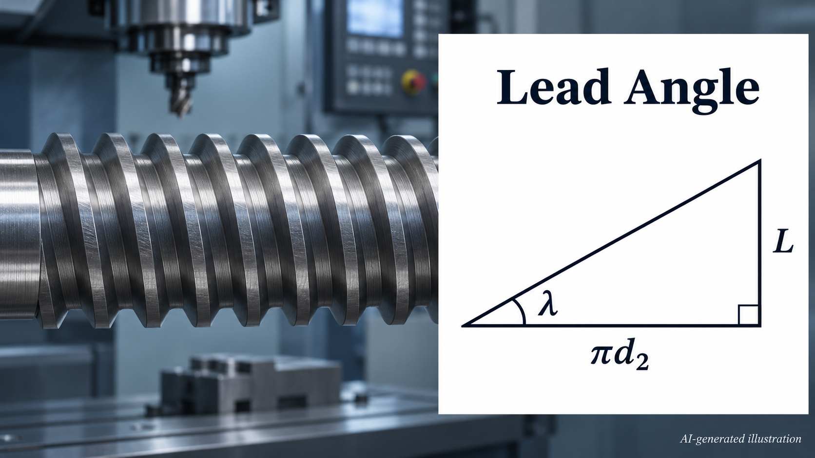
If a screw's helical thread path is unwrapped onto a flat surface, it forms a straight, sloping line rather than a curve. The thread lead angle describes the inclination of the helical path at the pitch diameter relative to a plane perpendicular to the screw axis. It's in degrees. The reference is taken around the shaft. Not along its length. Note that this geometric feature is for fastening screws, power screws, and other components with threads.
Lead Angle in Worm Drives
Now, let's think about a worm drive. A screw shaft coupled with a toothed wheel is used for the transmission of rotary movement between shafts at right angles. The worm lead angle is measured at the reference cylinder between the tooth helix and a plane perpendicular to the worm axis. It can be calculated from the worm lead and reference diameter using the same geometric relationship as for a screw thread. The worm provides continuous contact with the mating gear teeth. So, this geometry is an important aspect of their interaction.

Precision CNC Machining Service
Professional manufacturing, fast turnaround, and quality assurance.
How to Calculate Lead Angle
Lead Angle Formula
In order to calculate the lead angle, you need two measurements. Thread lead as well as pitch diameter. The first is the distance along the axis over one revolution. The second one is the working diameter at which the thread geometry is measured. The formula is:
λ=tan−1(Lπd2)
- λ is the angle in degrees.
- L is the thread lead (mm or inches).
- d₂ is the pitch diameter (mm or inches).
- π is the mathematical constant (3.1416).
How Thread Pitch and Number of Starts Affect Lead Angle
Thread pitch (P) is the axial spacing between corresponding points on adjacent threads. The number of starts (n) is the number of independent helices that provide a turn around the screw. The thread lead is calculated using L = n × P. If a thread has three starts, 2 mm pitch, and 20 mm pitch diameter, its lead is 6 mm and λ = 5.45°. For standard thread lead angle calculations, use the pitch diameter rather than the major diameter, because the lead angle is defined at the pitch diameter.
Single-Start vs. Multi-Start Threads
A single-start screw is a screw that has a single and continuous helical ridge. It performs well in an application that uses small amounts of axial movement over a number of revolutions. Another way to go is with multi-start designs. They have two or more intertwined helices to provide greater axial travel per revolution while retaining a finer pitch than a single-start thread with the same lead. Multi-start threads are useful when an application requires greater axial travel per revolution rather than fine linear positioning. However, it is difficult to produce them. Each independent helix must be machined with the correct angular indexing in order to maintain the thread geometry.
For projects involving threaded components, JLCCNC provides CNC machining services for custom parts with application-specific dimensional requirements. Upload your CAD files to get an instant CNC machining quote and DFM feedback from JLCCNC engineers.
Lead Angle vs. Helix Angle: What Is the Difference?
| Comparison Factor | Lead Angle | Helix Angle |
|---|---|---|
| Definition | Angle between the thread's helical path and a plane perpendicular to the screw axis. | Angle between the thread's helical path and the screw axis. |
| Reference Direction | Relative to the circumferential direction around the screw. | Relative to the axial direction along the screw. |
| Mathematical Formula | λ=tan−1(Lπd2) | β=tan−1(πd2L) |
| Angular Relationship | λ=90∘−β | β=90∘−λ |
| Effect of Increasing Thread Lead | Increases when pitch diameter is constant. | Decreases under the same conditions. |
| Example | A thread with a 10° lead angle has a shallow inclination to the circumferential direction. | The same thread has an 80° helix angle relative to its axis. |
The helix angle is measured relative to the screw axis and is complementary to the lead angle. Learn more about its definition and calculation in our guide to helix angle.
How Does Lead Angle Affect Mechanical Performance?
Lead Angle and Screw Transmission Efficiency
For power screws, some of the rotational energy is not converted into linear motion. Some is lost as heat through friction. The lead angle determines the direction of the force on the thread surfaces. Thus, the balance is affected. The higher the inclination, the higher the transmission efficiency in the normal operating ranges. But it also increases the torque needed to lift a given load at a given diameter. For an ideal square-thread screw, neglecting collar friction, efficiency can be η=tanλ/tan(λ+ϕ). λ is the lead angle, and φ is the friction angle.
Lead Angle and Self-Locking in Worm Drives
Not all the time does efficiency matter. Sometimes, sidestepping unwanted movement is of more worth. Self-locking is possible in worm drives. Under static conditions, the driven wheel cannot rotate the worm backward. This occurs when frictional resistance is greater than the force to reverse the mechanism. In a simplified worm-drive model, self-locking occurs when the worm's lead angle is smaller than the friction angle. A smaller lead angle generally makes self-locking more likely, although the actual behavior also depends on the friction conditions at the tooth surfaces. This is even more likely if the numbers are small. Therefore, these types of arrangements are suitable for lifting equipment and positioning mechanisms. But there's a catch. Static resistance can change under the influence of shock and vibration. Thus, independently operated holding brakes are required for safety-critical systems.
Factors Other Than Lead Angle
The real mechanical performance is not only dependent on geometric calculations. Sliding behaviour is affected by material pairing, surface roughness, lubricant viscosity, and operating temperature. Hardened steel against bronze may not behave the same as two steel parts against each other. The rotational velocity affects the formation of the lubricant film. Continued loading can increase wear if the contact surfaces are not protected. Even bearings, seals, and alignment of assembly cause power losses. Engineers need to consider the entire operating environment. They should not use only the thread geometry to predict the mechanical performance.
Lead Angle Considerations in CNC Thread Machining
CNC thread turning and thread milling
Thread Turning Insert Inclination and Flank Clearance
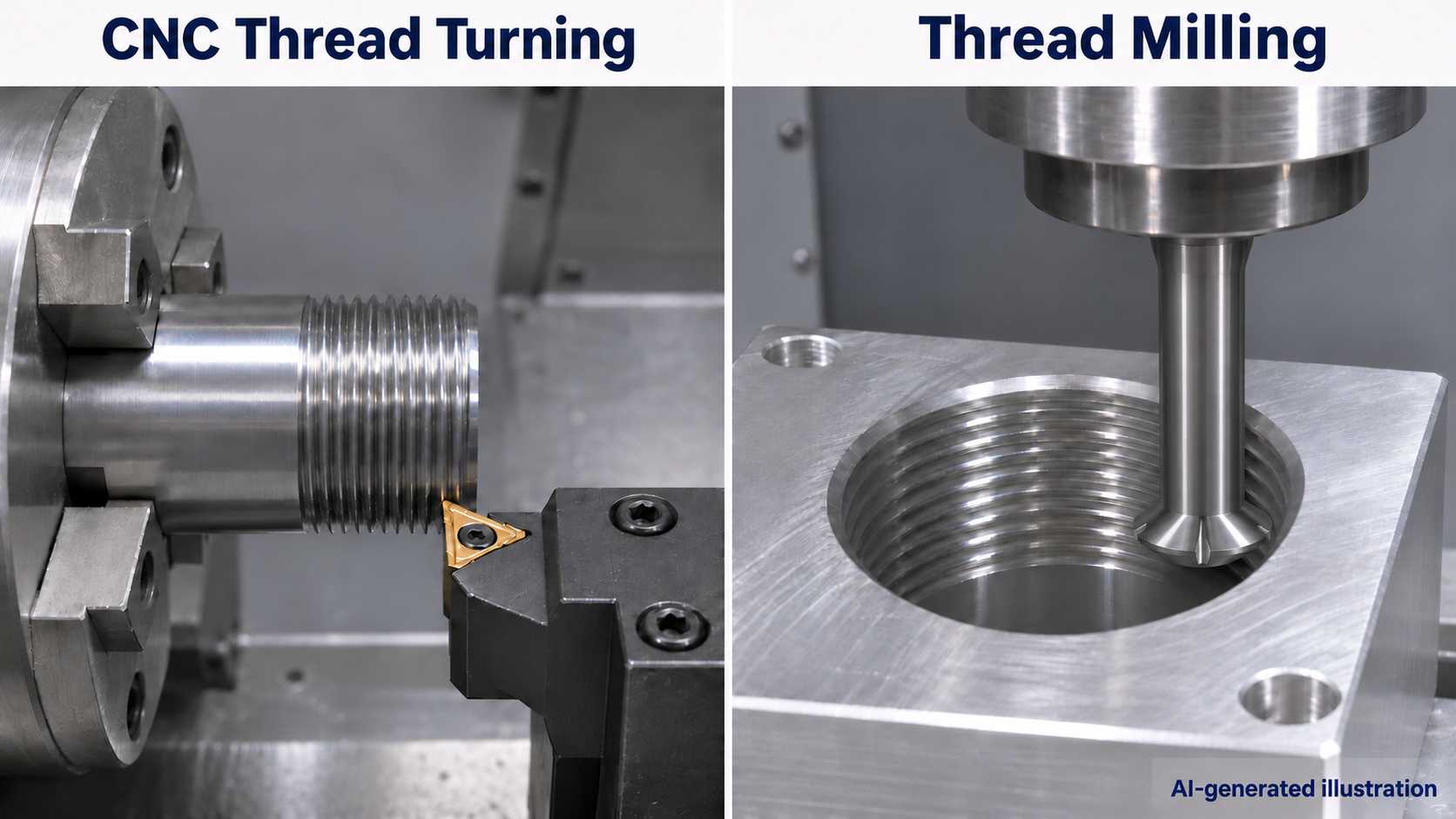
The cutting insert on the CNC thread turning has to be set at the right angle. So its sides do not rub against the flanks of the newly formed thread. The threading insert must be tilted to match the thread's helix angle so that both insert flanks maintain sufficient clearance from the thread flanks. Machinists select a suitable shim to set the required inclination. An incorrect setting can cause flank interference and uneven cutting-edge wear. Misalignment may cause one cutting edge to lose clearance. This causes uneven wear, excessive heat, or a poor surface finish. The setup is also dependent on the thread handedness, toolholder orientation, and profile geometry. Pay particular attention to threads with small profile angles, such as Acme and trapezoidal threads, because their geometry provides less flank clearance.
Lead Angle Considerations in Thread Milling
Thread milling has a different approach. It is not a stationary insert with a rotating work piece. But the cutter follows a preprogrammed spiral path. Here the thread lead angle affects the clearance between the cutter and the developing groove. For the context of high-inclination threads, the tool relief geometry must take care of the spiral so as not to rub the trailing surfaces on the workpiece. The cutter diameter is also important. Profile errors in internal threads may be caused by internal interference of an oversized tool. Using a properly sized cutter and checking its relief geometry ensures dimensional accuracy throughout the operation.
Need custom CNC-machined parts with threaded features? Submit your CAD files to JLCCNC for a project review and get a quote based on your part specifications and manufacturing requirements.
Precision CNC Machining Service
Professional manufacturing, fast turnaround, and quality assurance.
FAQs About Lead Angle
Q: Is Lead Angle the Same as Thread Pitch?
No. Thread pitch is a linear measurement that describes the distance between corresponding points on adjacent threads. Lead angle is an angular measurement expressed in degrees. Pitch describes thread spacing, not the inclination of the helical path.
Q: Is Lead Angle the Same as Helix Angle?
No. When measured from the same helical path, the lead angle and helix angle are complementary if the helix angle is measured relative to the screw axis. Their sum is 90°.
Q: At What Diameter Is Thread Lead Angle Measured?
Engineers use the pitch diameter (effective diameter) as the reference diameter for standard thread lead angle calculations, rather than the major diameter at the crests or the minor diameter at the roots.
Q: Does a Larger Lead Angle Always Improve Transmission Efficiency?
No. Increasing angle decreases the relative friction losses in conventional sliding-thread mechanisms. But it's not a panacea. Ball screws act differently. Their operation is dominated by rolling contact. Yet, efficiency can be altered by bearing losses as well as lubrication conditions.
Keep Learning
Lead Angle: Definition, Formula, and Applications
Lead Angle: Definition, Formula, and Applications
Titanium CNC Machining: Properties, Challenges & Best Practices
Titanium CNC Machining: Properties, Challenges & Best Practices A shop that's comfortable machining aluminum all day can still get caught off guard the first time a titanium job comes through. The part looks the same on the CAD screen, the toolpath strategy looks reasonable, and then the tool overheats, work-hardens the surface it just cut, and the finish comes out nothing like what aluminum would have produced at the same settings. Titanium isn't just "harder aluminum" — it behaves differently enough......
PEEK CNC Machining: Properties, Applications & Best Practices
PEEK CNC Machining: Properties, Applications & Best Practices Most plastics get chosen for CNC machining because they're easy to cut and cheap enough that the ease doesn't matter much either way. PEEK gets chosen for the opposite reason — it's genuinely difficult and expensive to machine, and engineers spec it anyway because nothing else in the plastic world does what it does at the temperatures and loads it's asked to handle. Understanding why PEEK earns that reputation, and what it actually takes to......
PTFE CNC Machining: Properties, Applications & Best Practices
PTFE CNC Machining: Properties, Applications & Best Practices PTFE — better known by the DuPont trade name Teflon — is a strange material to put on a CNC machine. It's soft, it barely holds a sharp edge itself, and it deforms under clamping pressure in ways that would ruin tolerance on almost any other engineering plastic. And yet it gets machined constantly, because nothing else offers PTFE's combination of an almost unbelievably low coefficient of friction and near-universal chemical resistance. Mac......
Laser Engraving Aluminum: Marking Methods & Surface Effects
Key Takeaways Laser engraving usually removes base material to create a recess. Laser marking is a broader term that can describe a surface-color change or material removal, so the process name alone does not define the final result. On aluminum, alloy and surface finish affect marking contrast. A light mark on dark anodized aluminum is a common design target, but the actual appearance depends on the finish and laser process. JLCCNC laser marking produces a recessed area 0.03–0.1 mm deep. The result i......
CNC Cutting Fluid: Types, Functions, Applications, and Selection Guide
Key Takeaways Cutting fluid in machining performs four functions simultaneously: cooling the tool and workpiece, lubricating the tool-chip interface to reduce friction, carrying chips away from the cut zone, and protecting machined surfaces from corrosion between operations. Different machining operations need different fluid priorities: high-speed aluminum milling may need adhesion control and chip evacuation, threading and tapping need strong lubrication, and grinding requires both cooling and fine ......