Helix Angle: Definition, Formula, and Machining Applications
17 min
- What Is a Helix Angle?
- How Does Helix Angle Affect Cutting Performance?
- High Helix vs. Low Helix Angles in Milling
- How Does Helix Angle Affect Drill Performance?
- FAQs About Helix Angle
Key Takeaways
- Helix angle refers to the angle between a cutting tool's spiral flute and its axis. It has an influence on chip removal, cutting force and how the cutting edge contacts the work material.
- The helix angles of most general-purpose end mills are about 30° to 40°. The lower angles promote cutting edge strength, and the higher angles can enhance the removal of chips and provide smoother cutting action.
- High-helix end mills typically have helix angles of 45° to 60° and are used for materials that generate long chips like aluminum. Higher axial cutting forces need to be taken into account for tool and workpiece stability.
- Twist drills also have helix angles. The typical range of general-purpose designs is in the neighborhood of 25° to 35° but will vary with the design of the drill and with the material to be drilled.
- There's no single "best" helix angle, it's dependent on the use case. Depending on the workpiece material, chip formation, cutting forces, tool rigidity and machining conditions.
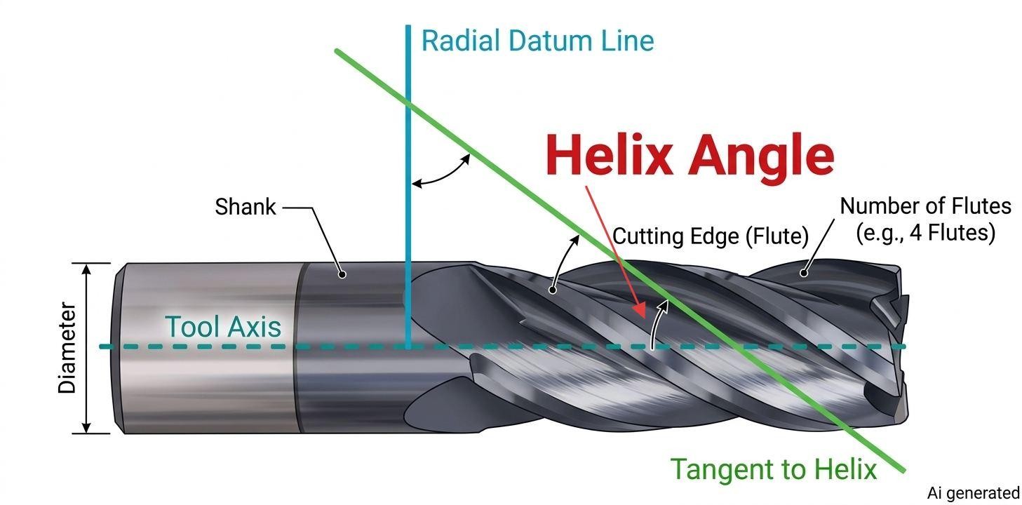
A labelled diagram depicting helix angle
The spiral grooves (flutes) on an end mill or twist drill do more than provide a path for chip removal. The angle they are at will have an impact on a number of elements of cutting performance.
The challenge is to know which geometry is right for your machining operation. For example, a helix angle suitable for aluminum may be inappropriate for hardened steel, thin-walled parts or drilling.
This guide explains how angle of helix is measured, how it affects end mills and drills, and what to consider when selecting one for a particular material and machining application.
What Is a Helix Angle?
A helix angle is the angle of the spiral flute relative to the lengthwise centerline of a cutting tool. In simpler words, it tells you how steep or shallow the spiral grooves are.
You find these helices in screw threads, spring coils, and the flutes of cutting tools. Helical gear teeth also follow this type of path around the gear. The same geometric principle applies in each case, although the diameter and reference surface used to define the angle depend on the application.
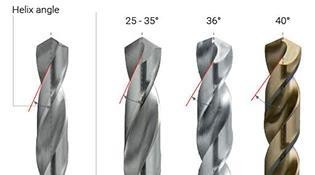
(Viking Drill) Low, medium and high helix angles
- Low helix angles (10° – 19°) gives a lengthy spiral.
- High helix angles (27° – 45°) gives a rammed (short) spiral.
- Normal Spirals have a Helix angle of (19° – 40°).
For general-purpose end mills, helix angles around 30° to 40° are a common starting point. The best choice still depends on the workpiece material, cutting conditions, and the type of operation. Even a modest change in helix angle can affect chip evacuation, cutting forces, and edge strength, so selecting the right geometry matters when planning a machining operation.

Precision CNC Machining Service
Planning a custom CNC-milled part? Upload your CAD files to get an instant CNC machining quote and DFM feedback from JLCCNC engineers.
How Is the Helix Angle Measured?
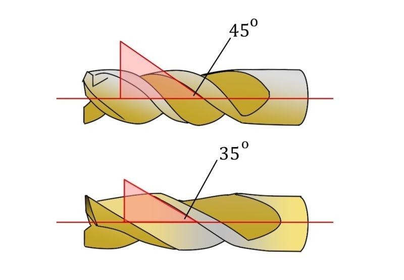
(Linkedin via Chase Reiter)
The reference is the cylinder's axis. Consider a straight line parallel to the axis, and then measure the angle between the straight line and the helical path.
At 0°, the path is straight along the axis, similar to the path on a straight fluted cutting tool. The greater the angle, the further the path will wrap around the cylinder for each increment of movement along the axis.
At 90°, the path would circle the circumference without advancing along the axis.
Helix angle can be checked using an optical comparator or a tool presetter equipped for this measurement. The other option is to measure the lead (L) on the flute and use the following formula to calculate the angle. The nominal helix angle is typically specified in a tool catalog. When the geometry of the tool is critical, verify it rather than relying only on the catalog value.
Helix Angle vs. Pitch, Lead, and Lead Angle
These terms describe related features, but they do not all measure the same thing.
Helix angle and lead angle are complementary if they refer to the same helix on the same diameter. The sum of their angles is 90°. Depending on the application and the reference, the term helix angle or lead angle is often used in thread references, and in cutting-tool catalogs.
Lead and pitch are lengths, not angles. For a single-start thread, lead equals thread pitch. For a multi-start thread, lead equals the number of starts multiplied by thread pitch. In a general helix calculation, use lead—the axial advance per revolution—rather than assuming that thread-pitch terminology applies to every helical feature.
| Term | What it describes | Reference |
|---|---|---|
| Helix angle | Angle between the helical path and the cylinder axis | Measured from the axis |
| Lead angle | Angle between the helical path and a plane perpendicular to the axis | Measured from the transverse plane |
| Lead | Axial distance the helix advances in one complete revolution | A length |
| Pitch | Axial distance between corresponding points on adjacent threads | A length |
Helix Angle Formula and Calculation Example
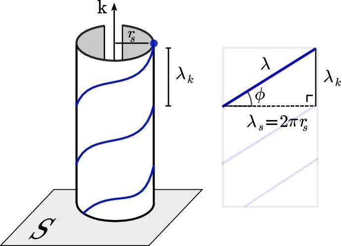
(Research Gate) Path of helical motion in space, wavelengths identified by unwrapping the cylindrical symmetry
Imagine a cylinder with a spiral line running around its surface. If you cut the cylinder lengthwise and unroll its surface flat, that spiral becomes the hypotenuse of a right triangle. The helix angle is the angle between that line and the cylinder's axis. Using this unwrapped view of the cylinder, you can calculate the helix angle from the triangle's sides.
rs = radius of the cylinder.
λs = circumferential distance for one complete revolution, equal to 2πrs.
λk = axial distance covered in one complete revolution. This is the lead (L).
λ = actual length of the helical path over one revolution. It is the hypotenuse.
ϕ = angle measured from the circumferential direction, not from the cylinder's axis.
The helix angle is measured from the cylinder's axis:
tan(β)=π×DL
Where:
- (β) = helix angle
- (D) = cylinder diameter
- (L) = lead, or axial distance covered in one revolution
Example: Consider a 10 mm end mill with a flute lead of 54.4 mm.
First, calculate the circumference:
C=πD=π×10=31.416mm
Then calculate the helix angle:
tan(β)=CL=31.41654.4=0.5775
β=tan−1(0.5775)≈30∘
Taking the inverse tangent gives a helix angle of approximately 30°.
You can also calculate the lead when the required angle is known. For a 10 mm tool with a 45° helix angle:
L=πDtan(β)
Substitute the values:
L=π×10tan(45∘)
Since tan(45∘)=1:
L=31.416mm
At a 45° helix angle, the axial lead equals the cylinder's circumference because the tangent of 45° is 1.
How Does Helix Angle Affect Cutting Performance?
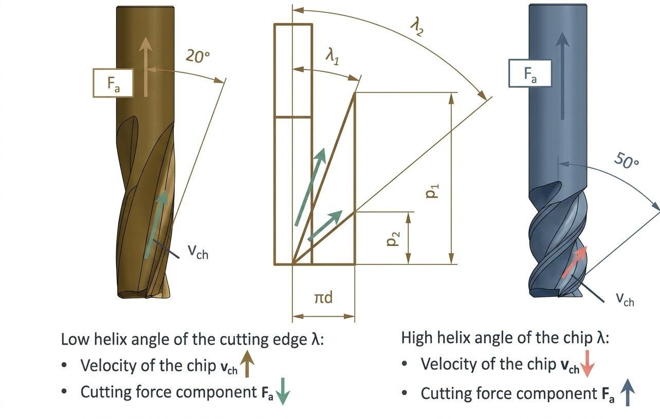
(Research Gate) Influence of helix angle on cutting force and chip formation
Angle of helix affects:
- How the cutting edge enters the material
- How chips move out of the cutting zone
- How cutting forces act on the tool.
These effects are connected, but improving one aspect can introduce another consideration, such as greater axial loading on the tool holder.
This is why two cutting tools with similar diameters and flute counts can behave differently during machining.
Cutting Forces and Axial Loads
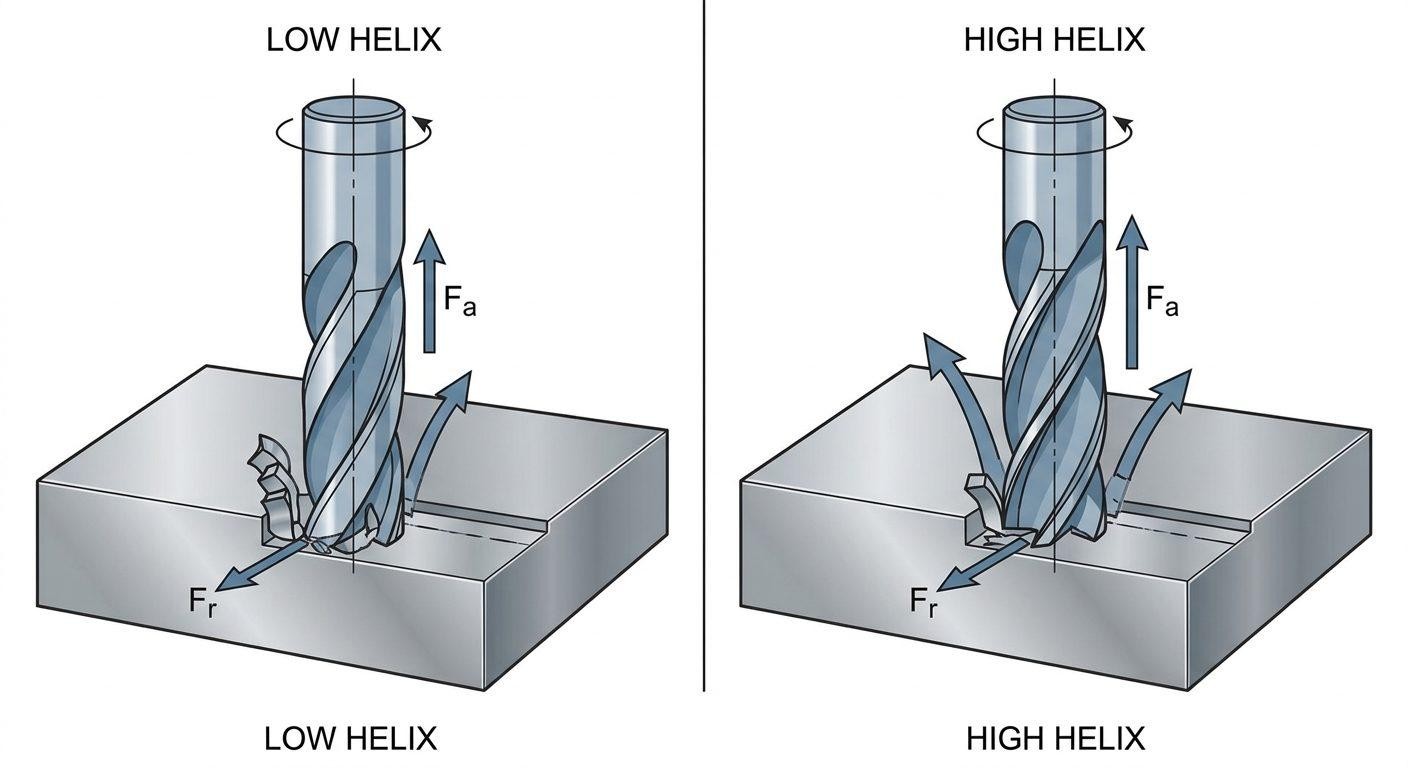
Depiction of radial and axial forces
During milling, cutting forces act in both radial and axial directions.
- Radial force (Fr) acts perpendicular to the tool axis
- Axial force (Fa) acts along the tool axis
- A higher helix angle generally increases the axial force component (Fa).
- A lower helix angle generally produces a larger radial force component (Fr) relative to the axial component.
Note
Secure tool clamping is especially important when using high-helix cutters, as axial cutting forces can increase the risk of tool pullout. A holder with sufficient pullout resistance is essential when this loading becomes significant.
Axial forces can also affect workpiece retention, particularly when machining thin or poorly supported parts. On thin walls, radial forces are often the more direct deflection risk because they push the wall away from the cutter.
Chip Evacuation and Cutting Smoothness
The spiral flutes move chips along the tool, away from the cutting zone.
The flutes have a stronger axial chip-flow direction at higher helix angles, which helps remove long chips from materials like aluminum. This is useful in operations where chips might otherwise remain in the cut and be recut.
A helical cutting edge enters the workpiece progressively along the tool axis rather than engaging its full axial length at once, as a straight cutting edge would. This distributes the cutting engagement and can produce a smoother cutting action.
Lower helix angle means less axial chip-flow action but it does not mean that it will necessarily result in chip packing. The flute count, flute size, depth of cut, coolant delivery and the machining strategy are also important factors in the chip evacuation process.
Cutting Edge Engagement and Tool Stability
A helical cutting edge does not engage the workpiece along its entire axial length at the same instant. As the tool rotates, engagement progresses along the flute. Increasing the helix angle generally increases the length of cutting edge engaged at a given axial depth of cut. This spreads the cutting load and can reduce abrupt force fluctuations, helping to limit vibration.
However, tool stability depends on more than helix angle. Cutting-edge strength is affected by rake and clearance angles, while tool rigidity also depends on the core diameter, flute depth, tool diameter, and unsupported length.
Low-helix tools are often selected when cutting-edge support and lower axial loading are priorities. High-helix tools offer smoother engagement and stronger axial chip flow, but require secure tool clamping.
High Helix vs. Low Helix Angles in Milling
End mills are available with a range of helix angles. Toolmakers commonly describe them as low-, standard-, or high-helix designs, although the angle ranges vary between manufacturers.
The table below summarizes their general characteristics. Treat these as design tendencies rather than fixed performance ratings.
| Helix Angle | Advantages | Limitations |
|---|---|---|
| High helix (45° to 60°) | Better chip evacuation and smoother cutting engagement. | Generates a greater axial force component, which may push the cutter toward the holder or pull it out, depending on the helix hand and cutting direction. |
| Low helix (15° to 30°) | Provides greater cutting-edge support and can be suitable for demanding cuts. | Less axial chip-flow action, which may make chip evacuation less effective for long chips. Generates a larger radial force component relative to the axial component, which can bend the cutter or push the workpiece away from it. |
| Feature | Low helix (about 15° to 30°) | Standard (about 30° to 40°) | High helix (about 45° to 60°) |
|---|---|---|---|
| Cutting-edge geometry | Can leave more material supporting the cutting edge, depending on rake and flute design | Balances edge support with cutting action | Often uses a more positive cutting geometry; edge strength depends on the remaining material behind the edge |
| Chip evacuation | Produces less axial chip-flow action, which may be less effective for long chips | Provides a balance between chip flow and edge geometry | Creates a stronger axial chip-flow direction, helping move long chips out of the cutting zone |
| Axial force | Generally produces a smaller axial force component relative to the radial component | Produces an intermediate axial force component | Generally produces a larger axial force component, increasing the importance of secure tool and workpiece clamping |
| Cutting-edge engagement | The edge engages with less gradual progression along the tool axis | Provides an intermediate progression of engagement | The edge engages more gradually along the tool axis, spreading cutting action over a longer portion of the edge |
| Common applications | Can suit abrasive or short-chipping materials and demanding cuts where edge support matters | Used for general-purpose milling across a range of materials | Often selected for aluminum, other long-chipping materials, and finishing operations where chip evacuation and smooth engagement matter |
| Tool example | 15° | 30° | 60° |
These are starting points, not universal material rules. The best choice also depends on the tool's rake and clearance angles, flute geometry, cutting parameters, workpiece material, and machine rigidity.
Helix angle is only one part of cutter selection. Flute count, coating, cutting-edge geometry, and tool material also affect how an end mill performs. See our guide to CNC machining tools and their applications for a broader look at these factors.
Variable Helix End Mills
A variable-helix end mill uses unequal helix geometry between flutes and/or a helix angle that varies along a flute, depending on the tool design. This changes the timing at which cutting edges enter the workpiece and can disrupt regular force fluctuations that contribute to chatter.
Variable helix and variable pitch are related but different features. Variable pitch changes the angular spacing between neighboring flutes, while variable helix changes the flute's spiral angle. Toolmakers often combine both in anti-chatter end mills.
By disrupting regular tooth-engagement patterns, these geometries can reduce vibration and improve stability. They are useful in operations involving long tool overhangs, thin walls, or difficult-to-machine materials. However, they do not eliminate chatter or guarantee higher cutting speeds and depths of cut. The result still depends on tool length, workholding, spindle speed, feed rate, and machine rigidity.
Variable-helix tooling is one way to manage vibration, but chatter can also result from excessive tool overhang, poor workholding, and unsuitable cutting parameters. Read our guide to the causes and solutions for machining chatter
How Does Helix Angle Affect Drill Performance?
In a twist drill, the flute helix affects the rake geometry along the cutting edge. The flute helix strongly influences the local rake geometry along the cutting lip. At the outer corner, it is closely related to the side-rake condition, but the effective rake also depends on the drill point geometry and grinding. A steeper helix gives a more positive rake at the outer corner, so the edge cuts with less resistance and the chip curls out more readily. That helps in soft, ductile materials like aluminum and copper, where chips are long and sticky. A shallower helix gives a less positive rake, a stronger edge and a stiffer flute, which suits hard materials where chipping is the risk.
General-purpose twist drills commonly use helix angles around 25° to 35°. High-helix drills often fall around 35° to 45° and are used for ductile materials such as aluminum that produce long chips. Low-helix or slow-spiral drills may use angles around 12° to 22° and are often selected for brass and other materials where a steep flute can cause the drill to grab. Classification ranges vary by manufacturer. If you wonder why a drill that works in steel seems to dig in or chatter in brass, the helix angle is a common reason. A drill ground to suit the material cuts more smoothly.
In deep-hole drilling, chip evacuation depends on more than the helix angle. Flute volume and shape determine how much chip can travel up the drill, while coolant delivery and the pecking strategy help prevent chip packing and drill breakage.
How to Choose an End Mill Helix Angle
Start with the workpiece material, then consider the operation and the rigidity of the setup. The right helix angle depends on how the tool needs to cut, where the chips need to go, and which cutting-force components the tool and workpiece can withstand.
The table below gives practical starting points for selecting an end mill. These are general recommendations, not fixed rules for every material or machining condition.
| Machining condition | Starting helix angle or tool type | Why this may work |
|---|---|---|
| Aluminum and other long-chipping materials | High helix, around 45° to 60° | Helps move continuous chips out of the cutting zone and provides more gradual cutting-edge engagement. |
| Steel, cast iron, and general-purpose milling | Standard helix, around 30° to 40° | Provides a practical balance between chip flow, cutting action, and edge geometry. |
| Abrasive or short-chipping materials | Low helix, around 15° to 30°, depending on the material and tool design | Can provide a more suitable edge geometry for materials that produce short chips or cause abrasive wear. Check the toolmaker's material recommendations. |
| Slotting and pocketing | High or standard helix, depending on chip space and setup | Chip evacuation is important because chips can remain in the cut and be machined again. Flute count, flute volume, depth of cut, and coolant delivery also affect chip removal. |
| Heavy roughing or interrupted cuts | Select a tool with suitable edge support; a lower or standard helix may be appropriate | Edge preparation, core diameter, flute geometry, and tool engagement matter more than helix angle alone. |
| Thin walls and floors | Choose based on the direction of the dominant cutting force and how the part is supported | Radial forces can deflect thin walls, while axial forces can bend thin floors. A higher helix shifts more of the force component toward the tool axis, so it is not automatically the better choice for thin sections. |
| Long tool overhang or vibration-prone setups | Consider a variable-helix or variable-pitch end mill | Unequal engagement timing can disrupt regular force patterns and reduce the risk of chatter. Tool overhang, workholding, and spindle conditions still matter. |
| Finishing passes | A standard or high helix, selected for the material and setup | A higher helix can provide smoother engagement, but surface finish also depends on runout, feed per tooth, tool condition, and machine stability. |
Tool life and productivity also depend on the complete cutter design. A high helix does not automatically shorten tool life through a weaker core, and a low helix does not automatically improve material removal rates. Core diameter, flute depth, cutting-edge geometry, coating, cutting parameters, and chip evacuation all affect performance.
Practical Example
Consider a CNC-machined aluminum 6061 housing with deep pockets and thin side walls. The pockets need enough chip clearance to prevent chips from collecting around the cutter, while the thin walls must remain stable during machining.
A high-helix end mill may help move aluminum chips out of the pockets and provide smoother cutting engagement. However, its greater axial force component also needs to be considered. A secure workholding setup, suitable tool overhang, and appropriate cutting parameters are important to keep the part stable.
A variable-helix tool may also help reduce chatter if vibration becomes a problem. The final choice depends on the pocket depth, wall thickness, cutter geometry, and machining setup. A high helix alone does not guarantee a better finish or prevent wall deflection.
Precision CNC Machining Service
For a custom aluminum housing or another precision-milled component, upload your CAD file to JLCCNC for a CNC machining quote starting from $1, with lead times as short as 3 days.
FAQs About Helix Angle
Q: What is the difference between helix angle and lead angle?
Under the convention used in this guide, the helix angle is measured from the axis, while the lead angle is measured from a plane perpendicular to the axis. They are complementary and add up to 90 degrees.
Q: Does a higher helix angle always improve surface finish?
No. A higher helix angle can produce more gradual cutting engagement and improve chip evacuation, which may benefit surface finish in suitable operations. However, it also increases the axial force component, which can affect machining stability. Surface finish still depends on tool geometry, runout, cutting parameters, tool condition, and workholding.
Q: What is a typical helix angle for an end mill?
Most general-purpose end mills fall between 30 and 40 degrees. Aluminum-oriented tools go to around 45 to 60 degrees, and tools for hard materials can go as low as 15 to 30 degrees.
Q: What is a variable helix end mill?
A variable-helix end mill has a helix angle that changes along the flute. This alters how the cutting edges engage the workpiece and can help disrupt regular force patterns that contribute to chatter. Variable pitch is different: it changes the angular spacing between adjacent flutes.
Popular Articles
• End Milling Explained: Types, Uses & Best End Mills for Metal & Wood
• End Milling vs Face Milling: Key Differences, Tools & Applications
• CNC Tooling 101: Choosing the Right End Mills and Cutters
• How to Choose the Right Cutting Tool Material (CNC & Lathe Guide)
• A Complete Guide to Tool Wear Detection and Maintenance in CNC Machining
Keep Learning
Helix Angle: Definition, Formula, and Machining Applications
Key Takeaways Helix angle refers to the angle between a cutting tool's spiral flute and its axis. It has an influence on chip removal, cutting force and how the cutting edge contacts the work material. The helix angles of most general-purpose end mills are about 30° to 40°. The lower angles promote cutting edge strength, and the higher angles can enhance the removal of chips and provide smoother cutting action. High-helix end mills typically have helix angles of 45° to 60° and are used for materials t......
Broken Tap Removal Methods and When to Use Them
Key Takeaways Method Best suited for Main limitation Pliers Exposed tap stub with enough material to grip May crush the stub or damage the surrounding surface Tap extractor Accessible flutes and a fragment that can still rotate Extractor prongs can break if the tap is seized Left-hand drill bit A centered fragment that is not fully seized May back out the fragment, but is not a reliable way to drill through hardened tap steel Carbide end mill Controlled removal on a rigid, accurately aligned machine M......
CNC Probing Guide: How CNC Probe Systems Work, Applications, and Benefits
Key Takeaways About CNC Probing CNC probing is on-machine measurement that replaces or reduces manual setup and inspection steps. A CNC probing system combines a probe body, stylus, signal transmission, and controller integration to measure workpiece position, tool length, feature dimensions, and surface location. CNC probing solutions range from basic workpiece location routines on a manual machine to fully automated in-process verification in unattended manufacturing cells. CNC probing simulation le......
Drill Point Angle: Selection, Materials, and Drilling Performance
Key Takeaways About Drill Point Angle A 118° point is used most often in steel and aluminum jobs because it drills without special setup changes on standard machines. 135° points show up more in stainless and tool steel work since they keep the drill from pushing hard at the center during entry. In aluminum and similar ductile materials, chips often come out in long strands when the point geometry does not support breakage. Hole entry stays more consistent when the drill point matches the material ins......
Jig vs Fixture: Key Differences and Applications in Machining
(AI generated) Drilling jig with guide bushings and CNC machining fixture holding a metal workpiece on a machine shop workbench. If you ask three machinists to explain the difference between jigs and fixtures, you’ll likely get three different answers. It’s one of those things that gets mixed up constantly, especially by anyone who isn’t actually standing at the machine. But when you’re planning a setup, that distinction becomes critical. How you hold a part changes everything: alignment, repeatabilit......
Types of Taps: How to Choose the Right Thread Tap for CNC Machining
(AI generated) Close-up of a thread tap cutting internal threads inside a metal workpiece. Tap breakage during blind hole threading is one of the most common production disruptions. This guide explains the different types of thread taps used in CNC machining and provides practical selection advice based on hole type, material, and machining conditions. What Is a Thread Tap and How Tapping Works What Is a Thread Tap? A thread tap is a cutting tool used to create internal threads inside a pre-drilled ho......