Chatter in Machining: Causes, Effects, and How to Reduce It
22 min
- What Is Chatter in Machining?
- What Causes Chatter in Machining?
- How to Identify Chatter
- How Chatter Affects Machining Performance
- How to Reduce Chatter During Machining
- Chatter in Common CNC Machining Operations
- Preventing Chatter Before Production
- FAQs about Chatter in Machining
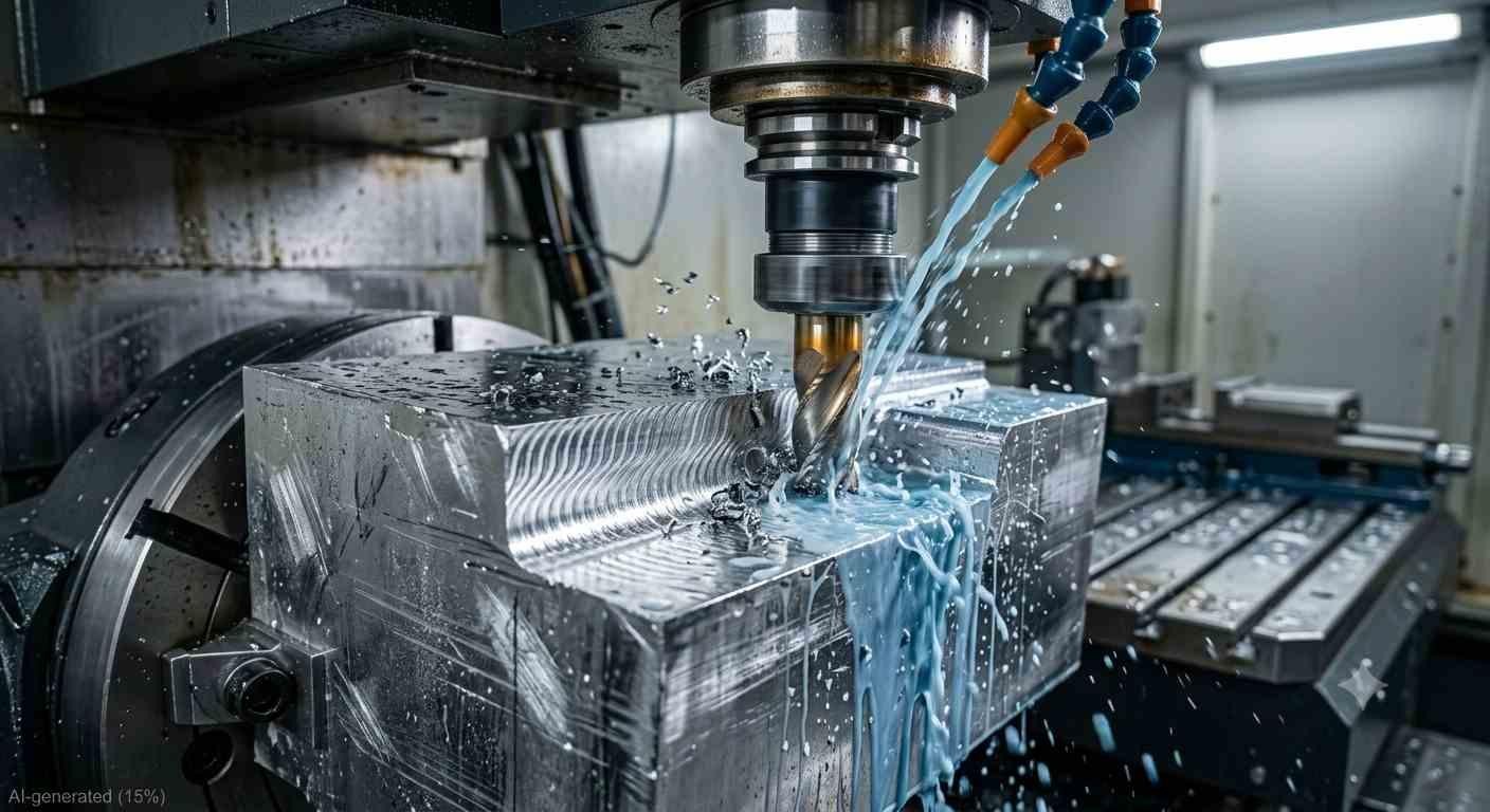
CNC milling operation producing visible chatter marks on an aluminum workpiece
Quick Chatter Diagnosis Checklist
| Symptom | Most Likely Cause | First Action |
|---|---|---|
| High-pitched squeal | Regenerative chatter | Change spindle speed ±15% |
| Chatter only in deep pockets | Excessive tool overhang | Shorten tool |
| Chatter on thin walls | Low workpiece rigidity | Improve fixturing |
| Chatter after tool replacement | Runout / holder issue | Check tool holder |
| Chatter only during finishing | DOC too small / rubbing | Increase feed or adjust speed |
It starts as a hum. Then it becomes a shriek. The surface finish that was Ra 0.8 µm on the last part comes off the machine looking like a washboard, the tool is half-dead, and nobody's entirely sure what changed between the last good part and this one.
Chatter in machining is one of those problems that experienced machinists can diagnose by ear and beginners spend weeks chasing. It's not random, it's a self-reinforcing vibration that follows predictable physics, which means it has predictable solutions. Understanding what actually causes chattering in machining, rather than just trying random parameter changes until it stops, is what separates a reliable fix from temporary luck.
Chatter is rarely caused by a single mistake. It usually comes down to tooling, workholding, machining strategy, and process planning working together. At JLCCNC, every CNC machining project goes through an engineering review before production to identify instability risks early, helping prevent chatter, improve surface finish, and reduce unnecessary machining time.

Precision CNC Machining Service
Professional manufacturing, fast turnaround, and quality assurance.
What Is Chatter in Machining?
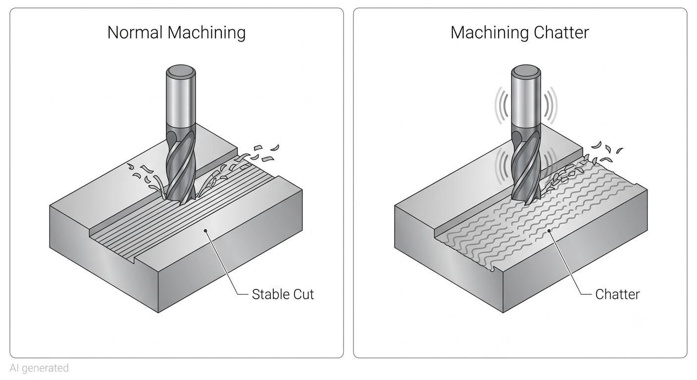
Comparison of stable CNC cutting with machining chatter
Chatter in machining is self-excited vibration that develops during cutting when the dynamic interaction between the cutting tool and the workpiece amplifies rather than damps the vibration already present in the system.
Chatter vs Normal Machine Vibration
Every machine vibrates. Spindle bearings rotate, motors hum, coolant pumps cycle, normal machining produces vibration at low, predictable amplitudes that don't affect part quality. Chattering in machining is different because it grows rather than staying constant. A small disturbance in cutting force excites vibration at the system's natural frequency. That vibration causes the tool to cut a wavy surface on the next revolution. The wavy surface generates a variable chip thickness that produces fluctuating cutting forces. Those forces amplify the vibration further. The cycle feeds itself until the chatter either destroys the tool, damages the part surface, or the operator changes something.
The self-amplifying nature is what makes chatter uniquely destructive compared to ordinary vibration. Background machine vibration stays stable, chatter grows until something stops it.
Why Chatter Develops During Cutting
The physics behind chattering in machining comes down to a concept called regenerative chatter. The tool cuts a surface, leaves a wavy pattern from the vibration during that cut, and then on the next revolution or pass, cuts over that wavy surface again. The variable chip thickness from the wavy surface creates variable cutting forces, which creates more vibration, which creates a wavier surface. Each cycle reinforces the last.
What determines whether vibration grows into full chatter or stays as background noise is the relationship between the cutting force variation and the damping in the system. If the system has enough damping, rigidity in the machine, fixture, workpiece, and tooling, the vibration loses energy faster than the cutting forces add it, and chatter doesn't develop. If damping is insufficient, vibration grows. Most chatter problems are fundamentally damping problems, which is why increasing rigidity is the first and most consistently effective fix.
What Causes Chatter in Machining?
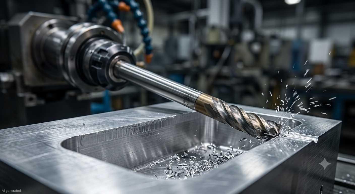
Long reach end mill machining a deep pocket
Machine Tool Rigidity and Dynamic Stability
A rigid machine damping transfers vibration into heat and internal stress rather than amplifying it. A flexible machine lets the spindle, table, and structure move in response to cutting forces, small movements that compound into chatter under the right conditions. Older machines with worn spindle bearings, loose column connections, or worn slideways have less dynamic stiffness than when new, making them more prone to chattering in machining even at parameters that worked fine when the machine was newer.
Dynamic stiffness matters more than static stiffness for chatter. A machine can feel solid under hand pressure and still have poor dynamic response at the frequencies that cutting forces excite. This is why chatter in machining can appear suddenly when spindle speed hits a particular value, the spindle speed has put the tooth engagement frequency at or near a resonant frequency of the machine-tool-workpiece system.
Many vibration issues actually begin with poor fixture design. Following proper CNC clamping guidelines helps create a much more rigid machining setup.
Tool Geometry, Overhang, and Wear
Tool overhang is one of the most direct causes of chatter in machining and one of the most controllable. The longer a tool extends from the holder, the more it deflects under cutting force, that deflection is the starting point for the regenerative cycle that becomes chatter. A tool at 4x diameter overhang is dramatically more susceptible to chattering in machining than the same tool at 2x diameter overhang, because the deflection under the same cutting force is roughly 8x greater (deflection scales with the cube of length for a cantilevered beam).
Worn tools cause chatter through a different mechanism. A dull cutting edge doesn't cut, it rubs and plows, generating fluctuating forces that would excite vibration in even a rigid setup. The combination of a worn tool and any flexibility in the system is a reliable recipe for chattering in machining even at parameters that were stable on the same part with fresh tooling.
Understanding the difference between roughing and finishing also helps reduce vibration because each operation uses very different tooling strategies and cutting parameters.
Workholding and Part Rigidity
The workpiece itself is part of the dynamic system. A part clamped rigidly to a solid fixture has high dynamic stiffness. A part that's clamped at two points with a large unsupported span in the middle is flexible, cutting forces in the middle of that span cause workpiece deflection that feeds the regenerative chatter cycle exactly as tool deflection does.
Thin-walled parts are the most common workholding-related chatter problem. The wall has low natural frequency and low damping, which means even moderate cutting forces at certain spindle speeds excite the wall into resonance. What causes chatter in machining on thin-walled parts is usually the part's own flexibility rather than the machine or tooling.
Cutting Parameters and Spindle Speed
Spindle speed is the parameter most directly connected to chatter through stability lobe analysis. At certain spindle speeds, the tooth engagement frequency coincides with or amplifies the natural frequency of the system, these are unstable zones where chatter develops regardless of how light the depth of cut. Between these unstable zones are stable pockets where the same depth of cut can be taken without chatter.
This is why increasing spindle speed sometimes eliminates chatter that reducing it didn't fix, rather than damping the vibration by cutting less aggressively, the operator has moved the operating point from an unstable lobe to a stable one. The higher speed produces the same or better surface quality with the same or heavier chip load because the dynamics are more favorable.
Depth of cut and feed rate both influence whether chattering in machining develops at a given speed. Deeper cuts increase cutting force, which increases the energy available to amplify vibration. But the relationship isn't linear, at a stable spindle speed, significantly deeper cuts may be taken without chatter than at an unstable speed where even light cuts generate chatter marks in machining.
Material Properties and Cutting Conditions
Materials that generate high cutting forces or exhibit work hardening, such as stainless steel and titanium, are generally more prone to chatter. Stainless steel and titanium are notorious chatter-prone materials partly because of their work-hardening tendency, the material ahead of the cut hardens, increases cutting resistance, generates a force spike, and that spike excites vibration.
Dry cutting removes an important source of damping, cutting fluid in the cutting zone acts as a slight damping medium and temperature stabilizer that influences dynamic behavior. Flood coolant may provide a small damping effect and improve thermal stability, although chatter is primarily controlled by machine rigidity and cutting dynamics.
How to Identify Chatter
Chatter Marks on the Machined Surface
Chatter marks in machining are the most definitive identification. They appear as regular, repeating wave patterns across the machined surface, sometimes visible to the naked eye, sometimes requiring a hand lens to distinguish from feed marks. The spacing between chatter marks corresponds to the vibration frequency divided by the relative velocity between tool and workpiece.
What separates chatter marks in machining from feed marks is the pattern regularity and orientation. Feed marks follow the tool path with spacing equal to feed per revolution. Chatter marks cross the feed direction, appear at a consistent spacing unrelated to the programmed feed, and often have a characteristic shiny or burnished appearance where the vibrating tool rubbed rather than cut cleanly.
Audible Noise and Excessive Vibration
Chattering in machining has a distinctive sound, a high-pitched squeal, howl, or intermittent screech that's immediately identifiable to anyone who's heard it. The frequency of the sound corresponds to the chatter frequency, which is typically in the range of 100-5000 Hz depending on the machine and tooling. Lower-frequency chatter often sounds like rhythmic knocking, while higher-frequency chatter produces a continuous squeal.
Vibration that's visible at the spindle, tool, or workpiece during cutting is another direct indicator. If the setup is vibrating enough to see, the surface is already collecting chatter marks in machining and tool wear is accelerating rapidly.
Changes in Cutting Behavior
Unexpected increases in spindle load or cutting power during a stable operation, intermittent tool deflection visible in the part dimensions, and inconsistent surface finish that varies across a single part are all indirect indicators that chattering in machining is developing even before it becomes severe enough to hear clearly.
Distinguishing Chatter from Other Machining Problems
Not everything that looks like chatter marks in machining is chatter. Built-up edge on the tool produces irregular surface defects without the regular wave pattern of chatter. Feed marks are regular but follow the tool path direction. Thermal expansion during machining produces dimensional drift without surface waviness. True chatter in machining has the combination of regular wave pattern, audible noise, and correlation with spindle speed, change the spindle speed by 10-15% and genuine chatter either gets worse, stays the same, or changes frequency, which distinguishes it from surface finish problems caused by other mechanisms.
How Chatter Affects Machining Performance
Surface Finish and Dimensional Accuracy
Does chatter ruin surface finish in machining? Yes, consistently and significantly. A surface with chatter marks in machining fails Ra requirements regardless of what the programmed feed rate should theoretically produce. The chatter marks add surface roughness that exceeds the tolerance band for any application requiring Ra below 1.6 µm, and at severe chatter levels, the marks are visible to the naked eye on any surface.
Dimensional accuracy suffers alongside surface finish. The vibrating tool cuts a path that deviates from the programmed path, finished dimensions on chatter-affected features are larger or smaller than nominal depending on the vibration direction, and the variation isn't consistent across the surface. Tight-tolerance features produced during chattering in machining routinely fail inspection.
Tool Wear and Tool Life
Chatter accelerates tool wear through two mechanisms. The vibrating tool repeatedly impacts the workpiece at the chatter frequency rather than maintaining smooth continuous contact, each impact shock loads the cutting edge beyond what steady-state cutting would produce. Simultaneously, the variable chip thickness from chattering in machining creates variable cutting temperatures that cycle the tool through thermal stress, which accelerates both flank wear and edge chipping.
A tool that would last 45 minutes at stable cutting conditions might last 8-10 minutes under severe chattering in machining. The wear isn't evenly distributed, chatter tends to concentrate wear at specific points on the cutting edge where the vibration geometry loads the tool most heavily.
Productivity and Cycle Time
Chatter forces parameters down to levels where it doesn't occur, lower depth of cut, lower feed rate, more passes. This directly increases cycle time. A part that could be roughed in 12 minutes at stable aggressive parameters takes 25 minutes at chatter-avoiding conservative parameters. Over a production run, that difference is significant machine time and cost.
Machine Reliability and Process Stability
Severe chattering in machining transmits vibration forces into the machine structure, spindle bearings, column connections, and slideways are subjected to repeated dynamic loads that accelerate wear. Machines that run with persistent chatter show accelerated bearing degradation and loss of geometric accuracy faster than machines where chatter is actively managed. Beyond machine wear, process instability from chatter means that identical parts run under identical parameters produce different results, the repeatability that production machining requires isn't achievable when chattering in machining is a persistent factor.
How to Reduce Chatter During Machining
Increase Machine and Setup Rigidity
The most fundamental approach to how to reduce chatter in machining is increasing the damping in every element of the setup. Shorten the tool. Use the shortest tool and holder combination that can reach the required feature. A 10mm reduction in tool sticking length can eliminate chattering in machining that nothing else fixed. Use the largest diameter tool that the feature geometry allows. Replace worn toolholders that have lost their interference fit precision. Verify that the spindle taper is clean and the holder is fully seated.
On the workpiece side, increase clamping force at the setup verification stage, not so much that the part deforms, but enough that the workpiece can't move in the fixture under cutting forces. Add auxiliary supports under unsupported spans of large or thin workpieces. Check fixture condition and replace worn clamping elements that have lost their holding force.
Reduce Tool Overhang and Improve Tool Selection
If a tool change is possible, reducing tool overhang is usually the first modification worth making to reduce chatter in machining. Going from 5x to 3x diameter overhang reduces deflection under the same cutting force by nearly 5x, the change in chatter behavior is often immediate and dramatic.
Toolholder selection affects chattering in machining through both mass and damping. Hydraulic and shrink-fit holders provide better dynamic balance and runout than collet chucks at the same tool length, which reduces the vibration excitation at the spindle-tool interface. Vibration-damping toolholders with tuned mass dampers are available for particularly problematic long-reach applications where tool overhang cannot be reduced.
Variable-pitch or variable-helix end mills change the timing of successive tooth engagements, which disrupts the regenerative chatter mechanism. Rather than each tooth hitting the wavy surface left by the previous tooth at the same phase angle, which amplifies chatter, variable geometry tools hit at changing phase angles that prevent the amplification cycle from developing. For persistent chatter in machining problems where parameter changes haven't solved the issue, variable-helix tooling is often the fix.
Optimize Spindle Speed, Feed Rate, and Depth of Cut
Changing spindle speed is often the fastest way to reduce chatter in machining because it shifts the tooth engagement frequency relative to the system's natural frequencies. If chatter develops at 8,000 rpm, try 7,000 rpm or 9,000 rpm. One of these speeds may fall into a stable lobe region where the same depth of cut runs without chatter.The change required to move between stable and unstable zones is often 10-20% of spindle speed, not a dramatic cut.
Depth of cut reduction is the most common intervention but not always the most effective for how to reduce chatter. Reducing depth of cut reduces the energy available to amplify vibration, which helps, but if the spindle speed is in an unstable zone, even very light cuts may still chatter. The combination of speed and depth adjustment, rather than just depth reduction, is more reliable.
Increasing feed rate is counterintuitive but sometimes effective for reducing chattering in machining. Higher feed rate increases chip thickness relative to edge radius, which reduces the specific cutting force variation that drives chatter, the tool is cutting more and rubbing less, which changes the dynamic character of the cutting process favorably.
Use Stable Toolpaths and Modern Machining Strategies
Adaptive clearing and high-efficiency milling (HEM) strategies maintain constant tool engagement angles throughout the cut, the tool load stays consistent rather than spiking at corners and full-width entry moves that typically trigger chattering in machining. Consistent load means consistent cutting force, which means less dynamic excitation that can grow into chatter marks in machining.
For thin-walled features, machining from both sides alternately rather than completing one face before the other keeps the wall balanced and supported throughout the operation. This reduces the wall's tendency to vibrate freely during cutting, which is the dominant cause of chattering in machining on thin-walled parts.
Verify Improvements Through Trial Cuts
The only reliable way to verify that changes have reduced chatter is to run a trial cut and inspect the results. Run a trial pass at the modified parameters, stop and measure surface finish, and check the audible character of the cut before committing to a full production run. Predicted stability improvements from parameter changes do not always translate to actual improvement if the root cause was something other than what was assumed.
Many chatter problems can be prevented long before the first chip is cut. Before production begins, JLCCNC reviews the machining approach for each project to help identify potential process issues before cutting starts. Upload your CAD files to receive a quotation and an engineering review for your project.
Precision CNC Machining Service
Professional manufacturing, fast turnaround, and quality assurance.
Chatter in Common CNC Machining Operations
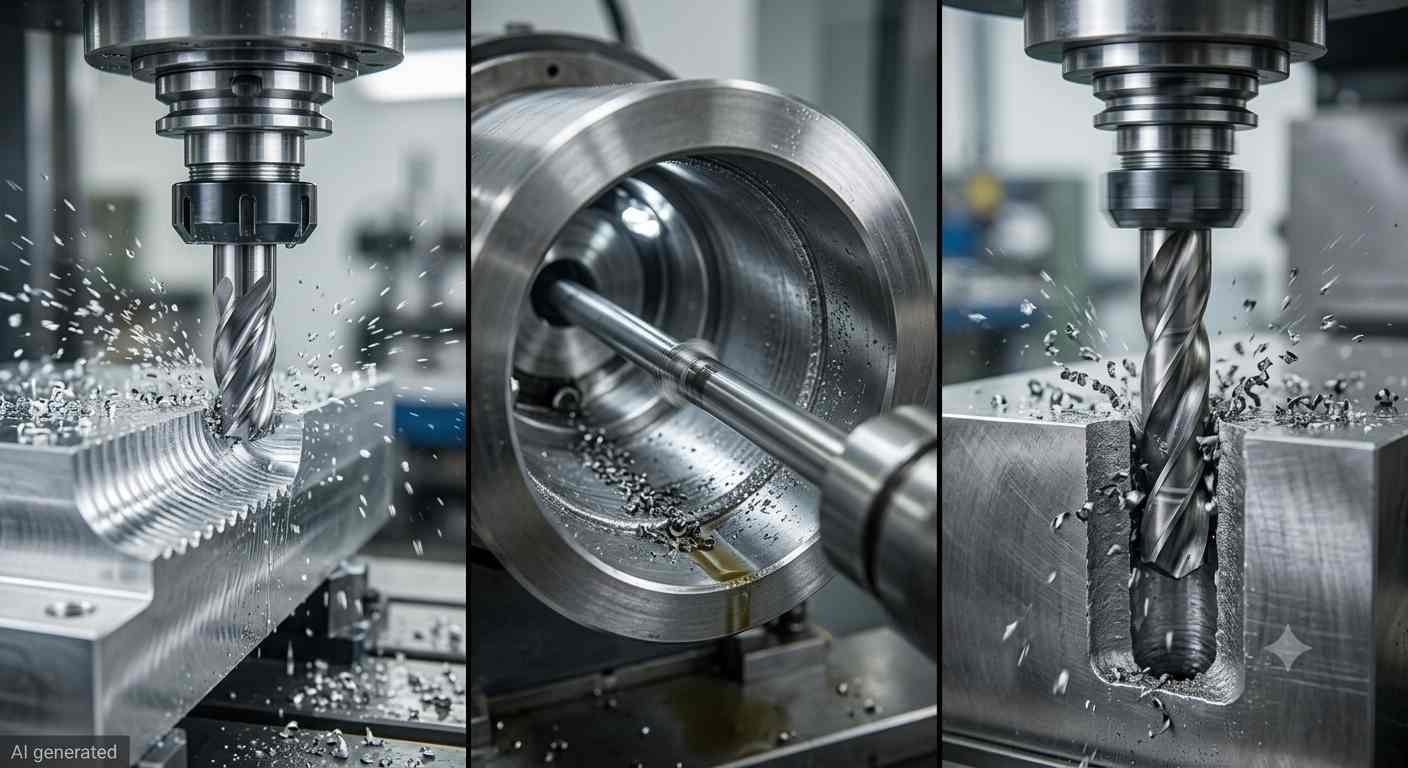
Chatter during milling boring and drilling operations
Milling
Milling chatter in machining is the most common form because the interrupted cutting action, each tooth engages and exits the cut periodically, creates a natural forcing frequency that can align with structural resonances. Long end mills in deep pockets, face mills on thin flanges, and ball nose tools on unsupported surfaces are the most frequent chatter scenarios in milling operations.
The characteristic chatter marks in machining from milling are typically oriented across the feed direction with spacing that indicates the vibration frequency. Pocket walls show the marks most clearly because the tool engagement condition is consistent around the pocket perimeter.
Turning
Chattering in machining during turning usually involves either tool overhang in boring operations or workpiece flexibility on long slender parts. A 200mm diameter shaft 1500mm long has very little radial stiffness at the middle, cutting forces at that location excite the workpiece's natural frequency, producing chatter marks in machining that run as helical patterns along the shaft length.
Boring bar chatter is the turning equivalent of long end mill chatter, the boring bar must reach into a deep bore, and the required overhang makes it flexible. Anti-vibration boring bars with tuned internal dampers are the standard solution for deep boring chatter that can't be resolved by parameter changes alone.
Drilling and Boring
Deep hole drilling produces chattering in machining through whirl, the drill drifts off-center under the asymmetric cutting forces from the two cutting lips and orbits around the programmed centerline. The resulting bore has lobed roundness error and chatter marks on the bore wall. Pilot holes that guide the drill for the first few diameters, peck drilling cycles that clear chips and reduce cutting force buildup, and through-tool coolant that flushes chips and reduces cutting temperature all help manage chatter during deep drilling.
Preventing Chatter Before Production
Design Parts for Greater Rigidity
Thin walls are the most reliably chatter-prone geometry in machining. Where function permits, increasing wall thickness reduces the wall's tendency to vibrate during cutting. Adding ribs to thin sections increases local stiffness without the mass penalty of solid material. Designing parts with accessible support surfaces, faces the fixture can contact to provide backing against cutting forces, reduces the unsupported spans where workpiece deflection drives chattering in machining.
Select Stable Cutting Tools and Holders
Before production starts, select tool length and holder type with chatter prevention in mind. The minimum tool length that reaches the feature, the holder type that provides the best dynamic stiffness at that length, and tool geometry suited to the material and operation are all decisions that prevent chatter marks in machining before the first cut runs rather than fixing them afterward.
Optimize CAM Toolpaths Before Machining
CAM toolpath selection influences whether chattering in machining develops during production. High-efficiency milling strategies that maintain constant engagement, rest machining approaches that minimize re-cutting of previously machined surfaces, and finishing passes that take a consistent, light, final chip all reduce the dynamic forcing that leads to chatter in machining. Review toolpaths specifically for conditions that could trigger chattering, full-width slot entries, sudden engagement increases at corners, and long unsupported radial cuts on thin features.
Validate the Machining Process Before Production
A trial cut on the first part of a new job identifies chattering in machining before it affects an entire batch. Run the first part at slightly conservative parameters, inspect for chatter marks in machining, confirm surface finish and dimensional accuracy, then adjust to production parameters. The cost of a trial cut is small compared to the cost of a batch of parts scrapped for chatter-induced surface finish failure.
Reviewing the entire machining process before production is one of the biggest advantages of following good Design for Manufacturing practices.
FAQs about Chatter in Machining
Q: What is chatter in machining?
Chatter in machining is self-excited, self-amplifying vibration that develops during cutting when the dynamic interaction between the tool and workpiece reinforces rather than damps vibration. It produces chatter marks on machined surfaces, degrades surface finish, accelerates tool wear, and indicates process instability.
Q: What causes chatter in machining?
What causes chatter in machining is typically one or more of: insufficient machine or setup rigidity, excessive tool overhang, poor workholding that allows workpiece movement, cutting parameters in an unstable speed-depth combination, worn tooling, or material properties that generate variable cutting forces. Most chattering in machining problems involve multiple contributing factors rather than a single cause.
Q: What is the difference between chatter and vibration?
All machine tools experience some level of low-amplitude, stable vibration during operation, and this is normal. Chatter is a self-excited vibration that grows over time because the cutting process feeds energy into the system faster than it can be dissipated. Normal vibration remains relatively constant, whereas chatter increases until the cutting conditions change or the process becomes unstable enough to require intervention.
Q: How do chatter marks affect surface finish?
Chatter marks in machining add regular wave patterns to the machined surface that increase Ra and Rz values significantly above what the programmed cutting parameters would otherwise produce. Does chatter ruin surface finish in machining? Yes, chatter marks in machining fail surface finish requirements regardless of feed rate, and parts with visible chatter marks are typically rejected at inspection.
Q: How can chatter be reduced?
Shorten tool overhang, increase workholding rigidity, change spindle speed by 10-20% to find a stable lobe, reduce depth of cut, use variable-helix tooling that disrupts the regenerative cycle, and switch to high-efficiency milling toolpaths that maintain consistent cutting engagement. Address the most likely root cause first rather than randomly changing all parameters at once.
Q: Why does chatter shorten tool life?
Chattering in machining creates impact loading on the cutting edge each time the vibrating tool contacts the wavy surface it previously cut, rather than smooth continuous cutting, the edge repeatedly shocks against a wavy surface at the chatter frequency. This impact loading causes edge chipping and accelerates both thermal and mechanical wear beyond what steady-state cutting would produce.
Q: Is chatter more common in milling or turning?
Chatter in machining occurs in both, but is most commonly encountered in milling because the interrupted cutting action creates a natural periodic forcing that can excite structural resonances. Deep boring in turning is a close second, where bar overhang requirements make the tool highly susceptible to chattering in machining. Turning of slender workpieces is the third most common scenario.
Q: Does spindle speed affect chatter?
Spindle speed directly affects chattering in machining because it determines the tooth engagement frequency relative to the system's natural frequencies. Certain spindle speeds put the engagement frequency in alignment with structural resonances, unstable zones where chatter develops easily. Shifting speed by 10-20% often moves the operating point to a stable zone where chattering in machining stops without any other change to the setup.
Q: Can adaptive toolpaths help reduce chatter?
Yes. Adaptive clearing and high-efficiency milling toolpaths maintain constant tool engagement angles rather than allowing sudden changes in chip load that create dynamic forcing spikes. Consistent cutting force means less dynamic excitation, which reduces the probability of chattering in machining developing, particularly in pocketing and slotting operations where conventional toolpaths create full-width engagement that's a frequent trigger for chatter marks in machining.
Precision CNC Machining Service
Professional manufacturing, fast turnaround, and quality assurance.
Conclusion About Chatter in Machining
Chatter in machining usually results from an unstable cutting system rather than a single machining parameter. Once the source of the instability is identified, the problem often becomes much easier to correct. In many cases, relatively small changes to the setup, tooling, or cutting conditions are enough to restore stable machining.
Reviewing machining stability before production can help prevent unnecessary troubleshooting later and reduce the risk of scrap caused by unstable cutting. For projects with demanding surface finish or tight tolerance requirements, JLCCNC evaluates the machining approach before production to help ensure the process is appropriate for the part. Upload your CAD file to receive a quotation and an engineering review.
Keep Learning
Laser Engraving Aluminum: Marking Methods & Surface Effects
Key Takeaways Laser engraving usually removes base material to create a recess. Laser marking is a broader term that can describe a surface-color change or material removal, so the process name alone does not define the final result. On aluminum, alloy and surface finish affect marking contrast. A light mark on dark anodized aluminum is a common design target, but the actual appearance depends on the finish and laser process. JLCCNC laser marking produces a recessed area 0.03–0.1 mm deep. The result i......
CNC Cutting Fluid: Types, Functions, Applications, and Selection Guide
Key Takeaways Cutting fluid in machining performs four functions simultaneously: cooling the tool and workpiece, lubricating the tool-chip interface to reduce friction, carrying chips away from the cut zone, and protecting machined surfaces from corrosion between operations. Different machining operations need different fluid priorities: high-speed aluminum milling may need adhesion control and chip evacuation, threading and tapping need strong lubrication, and grinding requires both cooling and fine ......
Blind Hole Machining Guide: What Is a Blind Hole, Types of Holes, and Tapping Tips
What Is a Blind Hole? Types of Holes and CNC Hole Machining Explained In CNC machining, few operations challenge process control and tool stability as much as blind hole machining. A blind hole is a hole that terminates at a defined internal depth rather than breaking through the opposite surface. Because the cavity is enclosed at the bottom, chip evacuation, thermal behavior, tool wear, and dimensional accuracy become far more difficult to manage compared to through-hole machining. These constraints ......
Rake Angle in Machining: Machinists’ Guide to Perfect Cuts
What is Rake Angle? (minaprem) If you've ever stood in front of a CNC machine or a manual lathe, you know that the cutting tool's geometry isn't just some arbitrary design. Every angle, edge, and surface has a job to do, and one of the most important of those is the rake angle. We've been running machines long enough to know that rake angle can make or break your surface finish, tool life, and machining efficiency. In this guide, we're going to walk you through what rake angle is, how it works, and ho......
Sheet Metal vs CNC Machining: A Guide to Choosing the Right Method for Your Metal Parts
Quick Answer: Choose sheet metal for uniform-thickness enclosures, panels, and formed brackets when bends and production volume support lower unit cost. Choose CNC machining for variable wall thickness, precision bores, tight feature relationships, and complex 3D geometry. Use a hybrid design when a formed structure needs precision-machined interfaces. A quote comes back for a bracket, and it's priced as a CNC part — machined from solid aluminum, a few hours of spindle time, a per-part cost that makes......
What Steps Are Taken To Minimize Waste In CNC Machining Processes?
How to Reduce Waste in CNC Machining: 5 Practical Strategies Quick Answer: CNC machining waste is reduced mainly through DFM, near-net stock, efficient toolpaths, preventive tool maintenance, and alloy-segregated recycling. The biggest gains usually come before cutting: reduce unnecessary material removal and prevent scrap or rework. Every CNC-machined part starts as more material than it ends up being. A pocket gets milled out, a profile gets cut away, a boss gets faced down to size — and all of that......