Roughing and Finishing in Machining: Differences, Methods, and Applications
26 min
- What Is Roughing?
- What Is Finishing?
- Typical Machining Workflow: Roughing to Finishing
- Roughing vs Finishing: Key Differences
- Roughing Operations in CNC Machining
- Finishing Operations in CNC Machining
- Finishing Allowance: How Much Material Should Be Left?
- How Roughing and Finishing Affect Part Quality
- How Roughing and Finishing Affect Machining Cost
- Roughing and Finishing in Different Manufacturing Scenarios
- Common Mistakes in Roughing and Finishing
- Conclusion About Roughing and Finishing
- FAQ About Roughing and Finishing
Quick Comparison Between Roughing and Finishing
Typical surface finish ranges vary by material, tooling, machine rigidity, and cutting strategy.
| Factor | Roughing | Semi-Finishing | Finishing |
|---|---|---|---|
| Primary Goal | Maximum material removal | Stock preparation | Final dimensions and surface |
| Depth of Cut | 2-8mm | 0.5-2mm | 0.1-0.5mm |
| Feed Rate | High | Medium | Low |
| Surface Finish | Ra 3.2-12.5 µm | Ra 1.6-3.2 µm | Ra 0.4-1.6 µm |
| Tolerance | Rough (±0.5-1mm) | Medium (±0.1-0.3mm) | Tight (±0.01-0.05mm) |
| Tool Wear | High | Medium | Low |
| Cycle Time | Longest | Medium | Shortest per pass |
| Tool Type | Strong, coated inserts | Transitional | Sharp, fine-finish tooling |
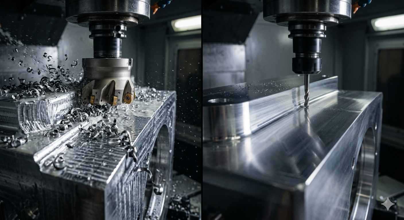
(AI generated) CNC roughing operation and precision finishing pass producing a smooth machined surface
Two operations. One part. Neither one works without the other.
Roughing cuts get the material close to the final shape fast, without caring about surface finish or precise dimensions. Finishing operations then take what roughing left behind and bring it to the dimension, tolerance, and surface quality the drawing specifies. Mix up the goals of these two stages, try to finish while roughing, or rough when you should be finishing, and you get slow cycle times, poor surface quality, premature tool failure, or parts that fail inspection.
Understanding what roughing and finishing actually do, and what separates them, is the foundation of intelligent process planning for any CNC machining operation.
What Is Roughing?
Roughing is the first machining stage, focused entirely on removing the maximum amount of material in the minimum amount of time. Rough milling doesn't care what the surface looks like or whether dimensions are precise. It cares about how quickly the workpiece can go from raw stock to something close to the finished shape.
Roughing cuts run at aggressive parameters: high depth of cut, high feed rate, and cutting speeds chosen for tool life and material removal rate rather than surface quality. The surface left behind after roughing is rough, visible tool marks, step lines from stepovers, and dimensional stock remaining on all surfaces intentionally, ready for the finishing stage to clean up.
The job of roughing is to do the heavy lifting efficiently. Every minute saved in roughing is a minute that goes toward productive machining time. For CNC customers, an optimized roughing strategy directly affects machining cost because most cycle time is often spent removing excess material. A roughing strategy that leaves consistent, controlled stock, the same amount remaining all over the part, sets up the finishing operation to work predictably and accurately.
What Is Finishing?
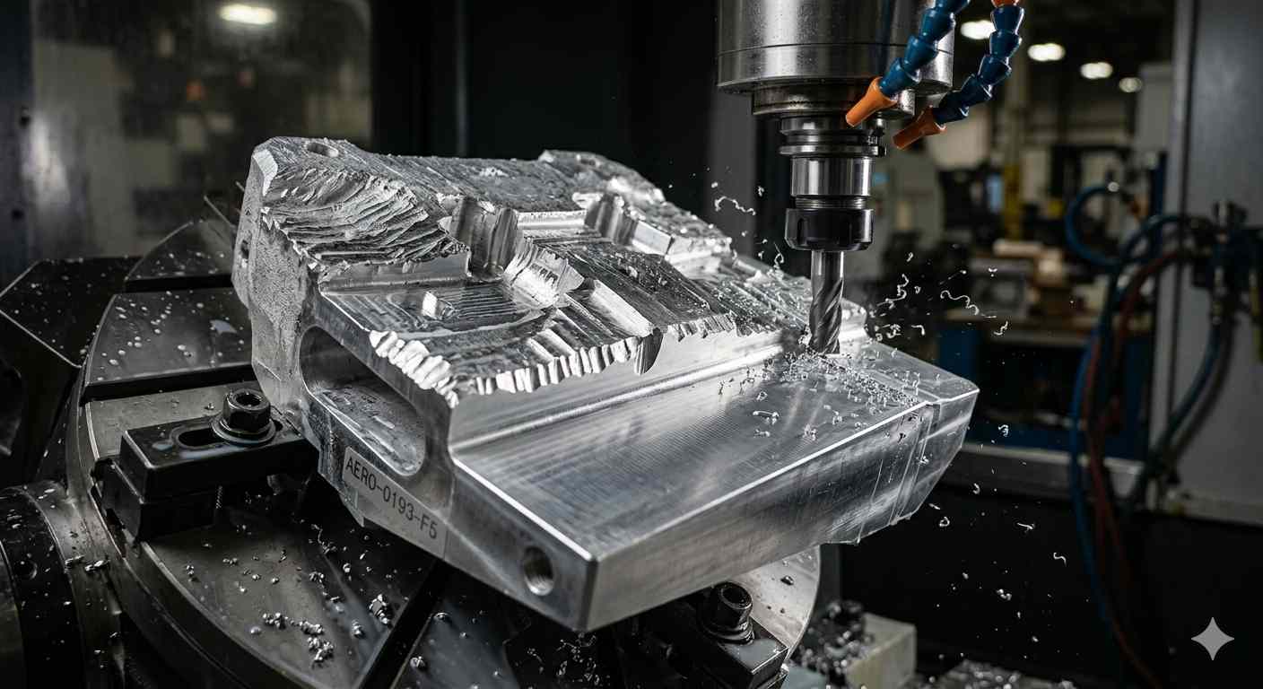
(AI generated) CNC semi-finishing operation showing a machined aluminum component transitioning
Finishing in machining is the final cutting stage that brings the part to its specified dimensions, tolerances, and surface finish. Where roughing prioritizes speed, finishing prioritizes accuracy. The depth of cut drops dramatically, the feed rate slows down, and tool selection shifts toward geometries optimized for surface quality rather than material removal.
Machining and finishing the same part well requires different thinking for each stage. Finishing operations often take a fraction of the total machining time but determine whether the part passes inspection. A part that was roughed perfectly can still be scrapped if the finishing stage is poorly executed, chatter, tool deflection, incorrect parameters, or insufficient finishing allowance all manifest at this stage.
Finishing cuts work on the controlled stock left by roughing, removing a precise, consistent layer to hit the final dimension and surface finish simultaneously.
What Is Semi-Finishing?
Semi-finishing sits between roughing and finishing in both purpose and parameters. It's not trying to remove bulk material at maximum rate, and it's not trying to hit final dimensions, it's evening out the stock left by roughing so the finishing operation has a consistent, uniform layer to remove.
Why does this matter? Rough milling leaves irregular stock, more remaining in corners where the tool couldn't reach efficiently, less on flat faces where the tool tracked cleanly. If finishing takes over from that irregular stock directly, the finishing tool encounters varying chip loads that cause deflection, chatter, and inconsistent surface finish. Semi-finishing removes those irregularities, leaving a controlled, even layer that finishing cuts can remove predictably and accurately.
For simple parts with forgiving tolerances, semi-finishing can be skipped. For precision components, complex geometry, and tight surface finish requirements, it's the step that makes the difference between finishing that works first pass and finishing that fights you.
The right balance between roughing, semi-finishing, and finishing depends on more than just the drawing. Material behavior, feature geometry, tolerance requirements, and production volume all influence the machining strategy. For custom CNC parts, reviewing these factors early often reduces cycle time and avoids unnecessary machining costs.
JLCCNC's engineering team evaluates machining processes during quoting to help identify practical roughing and finishing approaches before production begins.
Upload your CAD file to receive a manufacturability review and instant quote.

Precision CNC Machining Service
Professional manufacturing, fast turnaround, and quality assurance.
Typical Machining Workflow: Roughing to Finishing
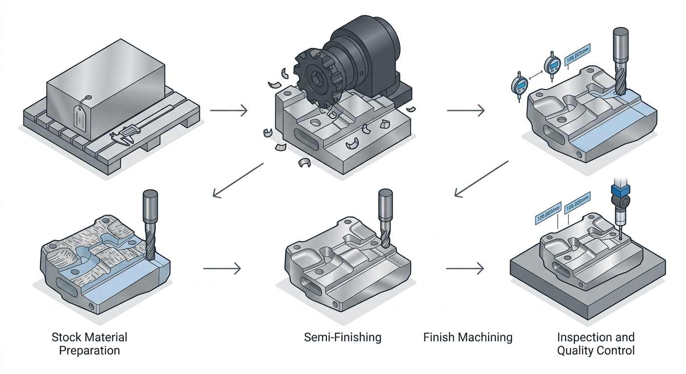
(AI generated) Workflow diagram
Stock Material Preparation
Before roughing cuts start, the stock material needs to be in a condition the machining program expects. This means correct dimensions, appropriate surface condition for workholding, and in some cases, particularly for aluminum and steel parts with tight final tolerances, stress relief if the material has significant internal stress from rolling or prior processing. Starting a roughing operation on material with significant residual stress produces parts that move dimensionally as stock is removed, which no amount of finishing skill can fully correct.
Rough Machining Stage
Roughing takes the workpiece from raw stock to rough shape. The machinist or programmer selects the highest material removal rate the machine, tooling, and workpiece setup can sustain without excessive deflection, tool wear, or workholding instability. Roughing typically leaves 0.3–1.5 mm of stock for subsequent operations on general CNC parts, while larger allowances may be used for molds, forgings, or distortion-sensitive components.
The roughing stage is where most of the machining time is concentrated on complex parts, deep pockets, large surfaces, significant volume reduction all happen here. Getting roughing efficient and fast directly reduces total cycle time and part cost.
Semi-Finishing Stage
Where required, semi-finishing follows roughing to clean up the stock consistency. Stepovers from rough milling passes, corner radii that roughing couldn't fully clear, and any areas of irregular remaining stock get addressed here. The parameters are intermediate, not as aggressive as roughing, not as fine as finishing, and the goal is uniformity, not final dimensions.
Finish Machining Stage
Finishing takes the semi-finished surface to final dimensions and surface finish. Parameters shift: depth of cut drops to 0.1-0.5mm, feed rate reduces to whatever produces the target surface finish with the selected tool geometry, and cutting speed adjusts for the finish-grade insert or end mill being used rather than the roughing tool. The finishing tool is sharper, has tighter tolerance on its geometry, and is fresh, a worn finishing tool produces inconsistent surface finish and may not hold dimensional accuracy.
Inspection and Final Quality Control
After finishing, the part is measured against the drawing requirements. Critical dimensions get checked with the appropriate instruments, micrometers, CMM, bore gauges, surface profilometers for Ra verification. Any dimensions outside tolerance need to be evaluated: can they be corrected with additional finishing passes, or is the part scrap? Finding this out at the machine, before the part comes out of the fixture, is preferable to discovering it after the setup is broken down.
Roughing vs Finishing: Key Differences
Machining Objectives
Roughing and finishing have objectives so different that treating them as the same operation type is the root cause of a surprising number of machining problems. The difference between roughing and finishing operations in machining comes down to this: roughing is a productivity operation, finishing is a quality operation. Confusing them, running finishing parameters during roughing (slow and wasteful), or running roughing parameters during finishing (inaccurate and rough), fails at both objectives simultaneously.
Material Removal Rate and Cycle Time
Roughing cuts generate the highest material removal rates (MRR) in the machining sequence. MRR in roughing can run 10-50x higher than in finishing, a roughing pass removing 3mm depth of cut at 0.3mm/tooth feed removes far more material per minute than a finishing pass at 0.1mm depth and 0.05mm/tooth. This is intentional. The roughing stage should dominate machine time on parts with significant material removal, and finishing should be a relatively small fraction of total cycle time for the same reason.
Cutting Parameters
Rough milling parameters are chosen to maximize chip load within the limits of tool strength and machine power. Large depths of cut, large widths of cut (though high-efficiency milling strategies modify this), and feed rates that keep the insert working hard without overloading it. Finishing parameters are chosen to control surface finish and dimensional accuracy, lighter cuts that eliminate the cutting force variations that cause deflection and dimensional error.
Dimensional Accuracy and Surface Finish
Roughing produces surfaces in the Ra 3.2-12.5 µm range with dimensional accuracy typically ±0.3-1mm from nominal. Finishing targets Ra 0.4-1.6 µm and dimensional accuracy in the ±0.01-0.05mm range for standard CNC machining operations. These aren't overlapping ranges, they're completely different performance categories, which is exactly why the operations that achieve them use different parameters, different tools, and different process logic.
Roughing Operations in CNC Machining
Common Roughing Strategies
Adaptive clearing is a CAM roughing strategy that shares many principles with trochoidal milling and high-efficiency milling (HEM), including constant tool engagement and reduced radial cutting loads. Instead of running a conventional full-width cut that overloads the tool on engagement and underloads it through the cut, adaptive clearing maintains a consistent tool engagement angle throughout the toolpath by using high-speed, small-stepover, curved paths that keep the cutter working at a consistent chip load. The result is dramatically better tool life, higher cutting speeds, and better heat management, all with smaller depth-per-pass in radial engagement but full axial depth of cut that makes adaptive clearing faster overall than conventional roughing on suitable geometry.
Conventional roughing, parallel passes at full stepover and moderate depth, remains appropriate for open roughing on simple geometry where the constant engagement of adaptive clearing doesn't provide the same benefit it does in pocketing or complex geometry. Large flat areas and simple profiles can be roughed efficiently with conventional approaches without the toolpath overhead that adaptive strategies add.
High-efficiency milling (HEM) takes the adaptive concept further by using long flute length, shallow radial depth of cut, and very high cutting speeds to maximize MRR while keeping tool temperatures manageable. HEM works particularly well in aluminum and soft metals where cutting speeds can be very high and heat generation is less critical.
Tool Selection for Roughing
Roughing cuts demand strong tools. For milling, this means carbide end mills with large core diameters (for rigidity under high chip loads), moderate to high helix angles depending on material, and coatings that handle heat, TiAlN for steel, uncoated or ZrN for aluminum. Indexable insert tools are common for large-volume roughing where the insert cutting edge geometry and grade can be optimized independently of the tool body, and where insert replacement is faster than regrinding solid carbide.
The tool for roughing doesn't need to produce a good surface finish. It needs to survive the chip loads, manage heat, and hold geometry long enough to rough the whole part without needing replacement mid-operation.
Typical Roughing Parameters
Actual roughing parameters depend on material, tool diameter, machine rigidity, and cutting strategy. For example, aluminum can generally be machined more aggressively than titanium or hardened steel because of its higher machinability.
For aluminum rough milling on a capable 3-axis machining center: cutting speed 200-600 m/min, feed per tooth 0.05-0.15mm, axial depth of cut 1.5-5x tool diameter with adaptive strategies or 0.5-1x with conventional, radial depth 40-80% tool diameter for conventional or 5-15% for adaptive.
For steel rough milling (1045 or similar): cutting speed 80-150 m/min, feed per tooth 0.03-0.1mm, axial depth 0.5-2x tool diameter, radial depth 30-60% for conventional.
These are starting points, actual parameters depend on machine rigidity, spindle power, workholding, and specific tool specifications.
Common Challenges in Rough Machining
Chatter during roughing is usually a workholding or setup rigidity problem rather than a cutting parameter problem, though parameters can make it worse. Long tool overhangs, inadequate clamping, and thin workpiece walls are the most common physical causes of chatter in roughing.
Heat buildup in materials with low thermal conductivity, titanium, stainless steel, nickel alloys, accumulates in roughing cuts and damages both the tool and the workpiece surface if coolant strategy isn't correct. Through-spindle coolant is often preferred for roughing difficult materials and deep cavities because it improves chip evacuation and tool life.
Tool deflection in deep pockets with long tool lengths causes the bottom of the pocket to be slightly oversized, which the finishing operation then needs to correct, but if the deflection-induced oversize is more than the finishing allowance, the wall is already too thin and the part is potentially scrap.
Roughing strategies vary significantly between processes, which is why understanding the differences between CNC milling vs CNC turning is important during process planning.
Finishing Operations in CNC Machining
Common Finishing Strategies
Profile finishing traces the part geometry with a consistent small stepover to generate the final surface. For prismatic parts, milled pockets, slots, planar surfaces, profile finishing follows the geometry in a single pass or a series of closely spaced passes with very light radial depth of cut. The tool follows the boundary of each feature precisely, removing the finishing allowance cleanly.
Contour finishing applies to 3D surfaces where the finishing tool follows surface contours with controlled scallop height, the small ridges left between adjacent tool passes. Scallop height determines the effective surface finish on 3D surfaces: smaller scallop requires tighter stepover, more passes, and longer cycle time, but produces finer surface finish. The scallop target gets calculated back to a stepover from the tool radius and the required Ra.
Fine passes, multiple overlapping finish passes, are used on particularly demanding surface finish requirements where a single finish pass at the achievable depth of cut leaves a surface that's still too rough. Each additional pass removes progressively less material and approaches the Ra limit of the tool-material-parameter combination.
Tool Selection for Finishing
Finishing tools are optimized for surface quality rather than material removal resistance. Sharp cutting edges, tight tolerances on tool geometry (runout, diameter, form), and coatings chosen for the final surface rather than heat resistance. Ball nose end mills for 3D surface finishing, flat end mills for floor finishing, and large-radius corner end mills for finishing where corner geometry matters.
Wiper inserts for finishing turning operations carry a flat land on the tool nose that produces significantly better surface finish at the same feed rate as a conventional insert, or the same surface finish at a higher feed rate. For production turning where both surface finish and cycle time matter, wiper inserts on finishing operations are often standard.
Surface Finish and Tolerance Requirements
Finishing in machining targets the Ra values and dimensional tolerances that the drawing specifies. For standard CNC milling, Ra 0.8-1.6 µm is achievable with good finishing parameters and sharp tooling. Ra 0.4 µm requires careful parameter optimization and very sharp tooling in good condition. Sub-0.4 µm from milling alone is very difficult, grinding or other operations become necessary.
Dimensional tolerance requirements of ±0.025mm or tighter on finishing passes require in-process measurement and tool offset correction. The thermal state of the machine, tool wear since the last offset adjustment, and material springback all contribute to dimensional variation that's perfectly normal but needs to be managed actively on tight-tolerance features.
Common Challenges in Finish Machining
Tool deflection in finishing is more damaging than in roughing because there's less stock to hide it. A 0.02mm deflection during roughing leaves a slight oversize that finishing removes. The same 0.02mm deflection during finishing means the finished dimension is 0.02mm off nominal, which may be within or outside tolerance, but either way it wasn't planned.
Chatter in finishing often appears on surfaces that were fine during roughing, because the finishing tool is longer and more slender relative to its cutting depth, and because the frequencies involved at the lighter chip loads are different from roughing chatter. Varying spindle speed, reducing overhang, and taking the finish pass in climb milling direction (where deflection tends to generate less chatter than conventional) are the standard first responses.
Finishing Allowance: How Much Material Should Be Left?
Why Finishing Allowance Matters
The finishing allowance is the controlled amount of material left on all surfaces after roughing (and semi-finishing where applicable) for the finishing operation to remove. It's not arbitrary, too little and the finishing tool can't clean up the roughing surface marks or correct any geometric irregularities left by roughing. Too much and the finishing tool is essentially re-roughing, with cutting forces and tool deflection that prevent it from achieving the intended surface finish and tolerance.
Getting finishing allowance right is one of the most important decisions in process planning because it connects roughing and finishing into a coherent sequence rather than two independent operations.
Typical Finishing Allowances for CNC Milling
For standard milled steel and stainless steel surfaces: 0.3-0.8mm per side is typical for surface finishing, with 0.5mm being a common default for general work. For aluminum: 0.2-0.5mm per side, since aluminum's better machinability means less variation from roughing passes to clean up. For tight tolerance features, precision bores, accurate shoulders, close-tolerance pockets, 0.2-0.3mm per side is usually appropriate, giving the finishing tool a consistent, light chip without leaving it a re-roughing job.
Rough milling with adaptive strategies tends to leave more consistent stock than conventional roughing, which allows slightly smaller finishing allowances because the variation to be corrected is lower.
Typical Finishing Allowances for CNC Turning
For turning operations, finishing allowance on diameter (total, not per side) typically runs 0.3-0.8mm for steel, 0.2-0.5mm for aluminum. Tight tolerance turned features, bearing seats, precision journals, mating diameters, often use 0.2-0.3mm total diameter allowance to ensure the finishing pass takes a consistent chip around the full circumference without the feed-force variation that a larger allowance can produce.
Factors That Affect Stock Allowance
Material springback, particularly in thin-walled parts and flexible geometries, means the part moves slightly as stock is removed in finishing, and the allowance needs to account for this movement. Larger allowance gives more opportunity to correct springback-induced geometry error.
Tool wear progression during roughing affects how consistent the remaining stock is, a dull roughing tool leaves different stock distribution than a sharp one. Managing roughing tool life and replacing tools at consistent intervals keeps the finishing allowance consistent from part to part.
Surface condition of the material matters too, rough stock with scale, casting skin, or significant surface irregularity may require larger allowances to clear the full irregular surface before achieving clean metal.
How Roughing and Finishing Affect Part Quality
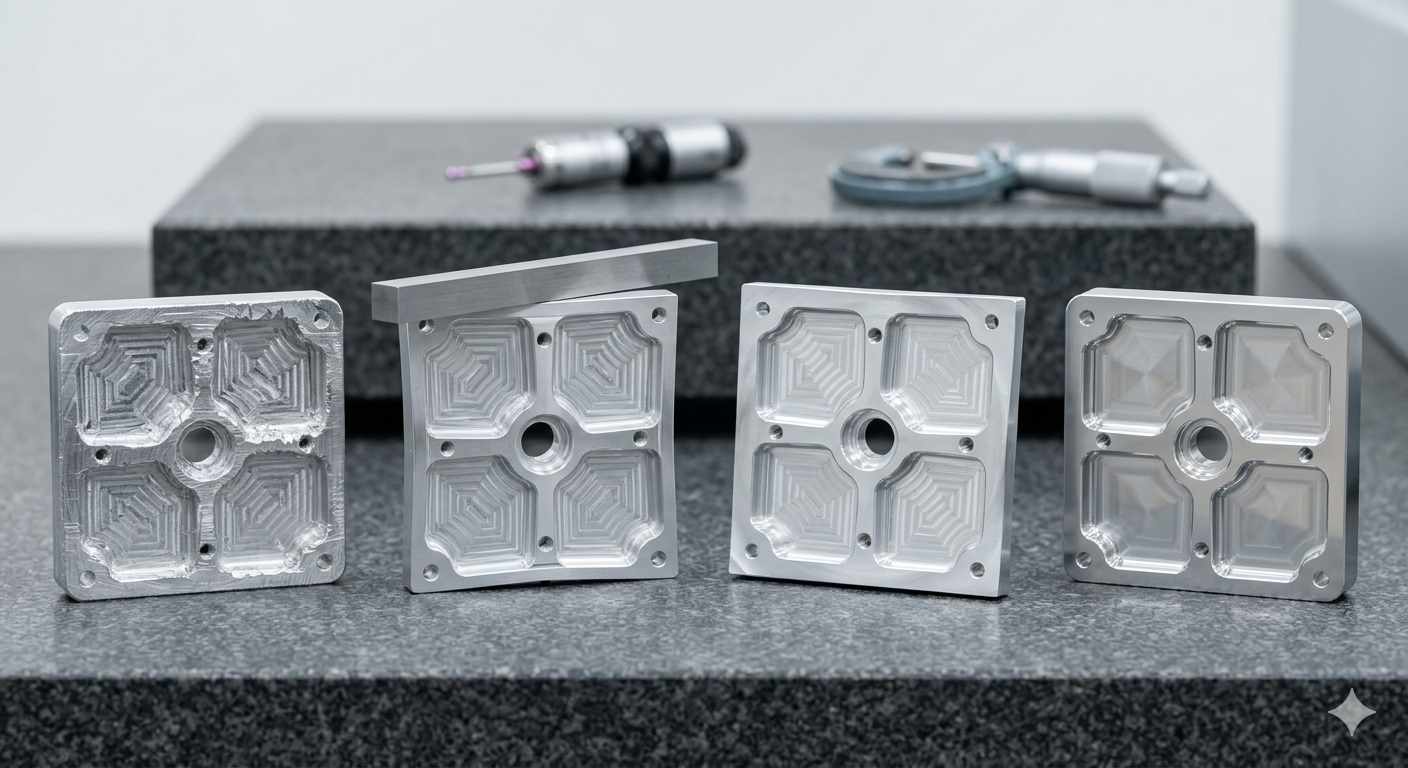
(AI generated) Four CNC machined aluminum components
Surface Finish Quality
Roughing produces the surface that finishing has to clean up. A roughing strategy that leaves consistent, uniform stock gives the finishing operation predictable cutting conditions, consistent chip load, consistent cutting force, consistent deflection behavior, all of which produce consistent surface finish. A roughing strategy that leaves irregular stock, hard edges from full-width engagement, or work-hardened surfaces from rubbing rather than cutting gives the finishing operation a harder job and produces more variable surface finish results.
Dimensional Accuracy
Dimensional accuracy in the finished part comes primarily from the finishing stage, but it's set up by the roughing stage. Roughing that distorts the part, through residual stress release, asymmetric material removal, or excessive heat introduction, changes what the finishing tool is working on. A pocket roughed from one side with all the material removed asymmetrically bows slightly as the stress redistributes, and finishing then chases a moving target.
Residual Stress and Part Distortion
Roughing introduces and releases residual stress. Aggressive roughing cuts in one direction on a part that was originally in stress balance from the rolling or forging process releases that stress asymmetrically, which causes the part to bow or twist. This is the reason that rough machining, stress relief, and then finish machining is a standard sequence for precision parts, the stress movement happens during roughing and the stress relief step, not during finishing.
Process Consistency
A well-defined roughing and finishing sequence is a repeatable roughing and finishing sequence. When the roughing strategy, tool, parameters, and allowance are documented and followed consistently, the input to the finishing operation is consistent, same stock left, same surface condition, same thermal state. That consistency translates directly into consistent finished part dimensions and surface finish, which is what production efficiency requires.
The most efficient machining projects aren't won during the finishing pass. They're won long before production starts with the right tooling strategy, machining process, and DFM review.
How Roughing and Finishing Affect Machining Cost
Tool Consumption
Roughing consumes tools faster than finishing due to the higher chip loads, higher cutting temperatures, and harder working conditions. In production environments, roughing tool consumption can be a significant cost driver, particularly in difficult materials. The economics favor durable roughing tools (indexable inserts with established replacement intervals) over solid carbide tools that are slower to replace, and justify through-spindle coolant investment that extends roughing tool life significantly in steel and stainless.
Finishing tools typically last much longer per tool because chip loads are light and temperatures are lower. But finishing tool condition directly determines surface finish and dimensional accuracy, a slightly worn finishing tool that would be acceptable for another pass might produce a surface that's just over the Ra limit, making tool management in finishing more quality-critical even if tools are changed less frequently.
Machine Time
Roughing cuts dominate machine time for parts with significant material removal. Optimizing roughing, better strategies, higher speeds, more aggressive parameters where the machine and tooling allow, has the greatest impact on total cycle time reduction. Finishing machining contributes less to total machine time but can't be compressed as easily without sacrificing dimensional accuracy and surface finish.
Surface Finish Requirements
Tighter surface finish requirements add finishing time. Achieving Ra 0.4 µm instead of Ra 0.8 µm may require an additional light pass at reduced feed, which adds cycle time even though the material removed is negligible. At production volumes, this additional time is a real cost that needs to be balanced against whether Ra 0.4 µm is actually functionally required or whether Ra 0.8 µm serves the application equally well.
Tolerance Requirements
Tight tolerances add cost at the finishing stage through slower parameters, in-process measurement, tool offset corrections, and higher first-article rejection risk. A part held to ±0.025mm costs more to produce than the same part held to ±0.1mm because the finishing process requires more care, more verification, and more correction actions to hit the tighter window consistently.
Material Type
Difficult materials, titanium, nickel superalloys, hardened steels, increase both roughing and finishing costs through higher tool wear rates, lower cutting speeds, and more demanding process control requirements. The roughing to finishing sequence remains the same, but every parameter gets adjusted downward and tool consumption goes up, which multiplies cost versus easier materials like aluminum.
Roughing and Finishing in Different Manufacturing Scenarios
| Manufacturing Scenario | Roughing Approach | Finishing Approach | Key Priority |
|---|---|---|---|
| Prototype & Low-Volume Production | Conservative roughing allowances to reduce scrap risk. Semi-finishing may be skipped to save programming time. | Conservative finishing parameters focused on accuracy rather than speed. | Getting the part correct on the first attempt. |
| High-Volume Production | Optimized adaptive roughing strategies maximize material removal rates (MRR) and machine utilization. | Highly repeatable finishing processes with predefined tool life management and automated wear compensation. | Lowest cycle time and consistent quality across thousands of parts. |
| Mold & Die Manufacturing | High-efficiency roughing removes large volumes of hardened steel while controlling tool load. | Semi-finishing prepares complex surfaces, followed by fine finishing with ball nose end mills and tight stepovers for superior surface quality. | Achieving complex geometry and minimizing manual polishing. |
| Aerospace & Precision Components | Aggressive roughing within material limits while carefully controlling heat generation, tool wear, and residual stress. | Precision finishing with in-process measurement, tool offset corrections, and comprehensive inspection. Stress relief may occur between roughing and finishing stages. | Tight tolerances, dimensional stability, and process reliability. |
Common Mistakes in Roughing and Finishing
Leaving Insufficient Material for Finishing
When roughing removes too much, leaving 0.05mm instead of 0.3mm, the finishing tool has almost nothing to remove. This seems like it saves finishing time, but it actually creates problems: the finishing tool can't correct any geometry variations left by roughing, any tool deflection during finishing immediately affects the final dimension, and the part is dangerously close to being undersize if any deflection occurs. Adequate finishing allowance is what gives the finishing stage its ability to produce accurate, clean results.
Removing Too Much Material During Finishing
Taking a heavy finishing cut, trying to combine semi-finishing and finishing into one pass, defeats the purpose of having a finishing stage. Heavy finishing cuts produce cutting forces and tool deflection similar to semi-finishing, which means the surface finish and dimensional accuracy are similar to semi-finishing, not to proper finishing. If the part needs tight tolerance and good Ra, it needs a proper light finishing cut with parameters chosen for that goal.
Using the Same Strategy for Both Operations
Rough milling with a finishing tool is expensive and slow, sharp finishing tools wearing out on heavy cuts. Finishing after roughing with the same aggressive parameters produces a surface indistinguishable from the roughed surface. These two stages need different tools and different parameters because they have different objectives. Treating them as the same operation by running one set of parameters for the whole job is a false efficiency that produces neither good rough machining and finishing results.
Ignoring Tool Deflection and Part Rigidity
Deflection is the invisible variable in both roughing and finishing. During rough milling, deflection means the actual depth of cut differs from the programmed depth, which affects how much finishing allowance remains. During finishing, deflection means the finished dimension differs from the programmed dimension. Planning the machining sequence to minimize overhang, maximize workpiece support, and use the shortest tool that reaches each feature manages deflection rather than hoping it's small enough to ignore.
Conclusion About Roughing and Finishing
Most machining problems that appear during finishing actually start much earlier. Uneven stock, excessive tool deflection, poor roughing strategies, or insufficient allowance all make the final pass harder than it needs to be.
A stable process is built step by step. Roughing creates the foundation. Semi-finishing, when needed, helps control stock consistency. Finishing then removes a predictable amount of material instead of compensating for problems left behind.
For custom CNC parts, the best results usually come from process planning before the machine starts cutting. Tool selection, stock allowance, and machining sequence all influence cycle time, dimensional accuracy, and overall production cost.
At JLCCNC, machining strategies are reviewed during the quoting stage so potential manufacturing issues can be identified before production begins.
Upload your CAD files to get an instant CNC machining quote and DFM feedback from JLCCNC engineers.
Precision CNC Machining Service
Professional manufacturing, fast turnaround, and quality assurance.
FAQ About Roughing and Finishing
Q: What is rough milling?
Rough milling is the aggressive first milling stage that removes the majority of material from a workpiece at maximum feed rates and depth of cut, leaving a controlled amount of stock on all surfaces for finishing operations to remove. Rough milling prioritizes material removal rate over surface quality and dimensional precision.
Q: What is finishing in machining?
Finishing in machining is the final cutting stage that removes the controlled stock left by roughing to bring the part to its specified final dimensions, tolerance, and surface finish. Finishing operations use lighter depth of cut, slower feed rates, and sharper tooling than roughing, prioritizing accuracy and surface quality over speed.
Q: What is the difference between roughing and finishing?
The difference between roughing and finishing operations in machining is in their objectives and parameters. Roughing maximizes material removal rate with aggressive parameters, producing rough surfaces and approximate dimensions. Finishing achieves final dimensional accuracy and surface quality with light, precise cuts. Roughing sets up the geometry; finishing delivers the specification.
Q: Can roughing and finishing use the same cutting tool?
Technically yes, but it's rarely optimal. Roughing wears tools rapidly through high chip loads and heat, while finishing requires sharp, precise cutting edges for surface quality. Using a roughing-worn tool for finishing produces inferior surface finish and potentially out-of-tolerance dimensions. Dedicated finishing tools in fresh condition produce better and more consistent results.
Q: How much material should be left for finishing?
For CNC milling: 0.3-0.8mm per side for standard steel operations, 0.2-0.5mm per side for aluminum. For CNC turning: 0.3-0.8mm on diameter for steel, 0.2-0.5mm on diameter for aluminum. Tight-tolerance features work better with the lower end of these ranges where roughing strategy leaves consistent stock.
Q: Why is finishing necessary after roughing?
Roughing cuts leave surfaces in the Ra 3.2-12.5 µm range with dimensional variation of ±0.3-1mm, too rough and too imprecise for most engineering applications. Finishing in machining removes the stock left by roughing in a controlled, precise operation that achieves the specified Ra and dimensional tolerance. Without finishing, the part fails both surface finish and dimensional requirements.
Q: How do roughing and finishing affect machining cost?
Roughing affects machining cost mainly through material removal time and tool consumption. Finishing affects cost through tolerance requirements, surface finish requirements, inspection, and process control.
Q: Which operation has the greatest impact on surface finish?
Finishing has the greatest impact on surface finish in machining. The Ra produced by finishing is what the finished part carries, roughing surface finish is irrelevant as long as it's completely removed by finishing. However, roughing indirectly affects surface finish by determining how consistent and clean the stock is that finishing has to work with.
Popular Articles
• Cutting with Precision: A Comprehensive Guide to CNC Water Jet Technology
• CNC Coolant Explained: Types, Maintenance & Safety
• Rake Angle in Machining: Machinists’ Guide to Perfect Cuts
• What Steps Are Taken To Minimize Waste In CNC Machining Processes?
• How EDM Wire Cutting Works: Complete Guide to Precision CNC Wire Cutting
Keep Learning
Chatter in Machining: Causes, Effects, and How to Reduce It
CNC milling operation producing visible chatter marks on an aluminum workpiece Quick Chatter Diagnosis Checklist Symptom Most Likely Cause First Action High-pitched squeal Regenerative chatter Change spindle speed ±15% Chatter only in deep pockets Excessive tool overhang Shorten tool Chatter on thin walls Low workpiece rigidity Improve fixturing Chatter after tool replacement Runout / holder issue Check tool holder Chatter only during finishing DOC too small / rubbing Increase feed or adjust speed It ......
What Is Tool Offset in CNC? Types, Setup & Best Practices
CNC tool offset setup with measurement overlay Key Takeaways CNC offsets connect programmed intent with actual cutter position. Length data guides Z-axis depth control. Radius data protects part size during contour milling. Geometry values define the cutter's measured baseline. Wear values support fine correction during production. Verified data lowers scrap risk before full machining. Good offset habits protect tools, fixtures, and parts. In the context of CNC machining , tool offset is the quiet set......
Trochoidal Milling: Complete Guide to High-Efficiency CNC Machining
Key Takeaways Trochoidal milling combines circular cutter motion with continuous forward feed. The cutter normally engages 5 to 20% of its diameter instead of making a full-width cut. A smaller engagement angle limits force changes during slotting and pocket roughing. Low radial engagement often allows greater axial depths of cut than conventional slot milling. CAM software calculates the circular path automatically from the selected machining parameters. This strategy is widely applied to titanium, s......
What Is Die Casting? Process, Materials, and Applications
Key Takeaways Die casting is a metal casting process that forces molten metal into a reusable steel mold under high pressure, producing parts with tight tolerances and good surface finish at high volume. Aluminum die casting is the most common form by far, thanks to its combination of light weight, decent strength, and good corrosion resistance. The die casting process runs through mold preparation, injection, cooling, and ejection in a cycle that can repeat every few seconds to minutes depending on p......
First Angle vs Third Angle: Understanding Orthographic Projection Methods
Key Takeaways Orthographic projection is the system that lets a 3D part be represented through multiple 2D views, front, top, side, and so on. First angle projection and third angle projection are the two standard methods for arranging those views, and they place views in opposite positions relative to the object. First angle projection is the ISO standard used across most of Europe, India, China, Russia, and many other countries following ISO standards Third angle projection is the standard in the Un......
Micro EDM Machining: Capabilities, Materials, and Applications for Precision Components
Key Takeaways About Micro EDM Machining Only electrically conductive materials can be machined. Hole diameters can reach below 50 μm on specialized equipment. The process produces almost no mechanical cutting force, making it suitable for thin or delicate features. Surface integrity still requires attention because recast layers and heat-affected zones may remain after machining. Micro EDM is often combined with CNC machining, with milling producing the main geometry before EDM finishes critical micro......