Drill Point Angle: Selection, Materials, and Drilling Performance
21 min
- What Is a Drill Point Angle?
- Why Drill Point Angle Matters
- Common Drill Point Angles and Their Applications
- Choosing Drill Point Angles for Different Materials
- How Drill Point Angle Affects Hole Quality
- Drill Point Angle vs Other Drill Geometry Features
- How to Select the Correct Drill Point Angle
- Best Practices for Selecting Drill Point Angles
- Conclusion About Drill Point Angle
- FAQ About Drill Point Angle
Key Takeaways About Drill Point Angle
- A 118° point is used most often in steel and aluminum jobs because it drills without special setup changes on standard machines.
- 135° points show up more in stainless and tool steel work since they keep the drill from pushing hard at the center during entry.
- In aluminum and similar ductile materials, chips often come out in long strands when the point geometry does not support breakage.
- Hole entry stays more consistent when the drill point matches the material instead of using a universal geometry for all jobs.
- Wear usually starts near the center of the drill first, especially when drilling harder steels, where the entry load stays concentrated.
- Exit burr size changes between materials, even if the same drill and feed settings are used on the same machine.
- Deep holes need better chip flow control, since chips packed inside flutes can mark the hole surface and slow cutting.
- Material type, hole depth, machine stiffness, and required hole finish are usually checked together before choosing the drill point angle.
Drill point angle receives attention during tooling selection because the drill tip is the first section of the tool that engages the workpiece. Small changes in point geometry can produce noticeable differences in chip formation, thrust load, hole condition, and wear distribution during production drilling.
In CNC machining, drill performance is not evaluated by hole diameter alone. Engineers also review:
- Hole straightness
- Entry condition
- Burr formation
- Surface finish
- Tool life
The drill point contributes directly to many of these outcomes because cutting begins at the tip before the remaining cutting edges become fully engaged.
Material behavior also influences drill geometry selection. For example, aluminum alloys, stainless steels, cast irons, engineering plastics, and composite materials do not respond the same way during penetration. A geometry that performs well in free-cutting aluminum may generate excessive heat, unstable chips, and accelerated wear in stainless steel.
In addition, deep holes require stable chip evacuation. Thin-wall components demand controlled entry behavior. High-volume manufacturing often focuses on predictable wear patterns to reduce unexpected tool changes during machining.
For these reasons, drill point angle selection extends beyond a catalog specification. It becomes part of the overall drilling strategy used to balance hole quality, tool longevity, material behavior, and production stability.
What Is a Drill Point Angle?
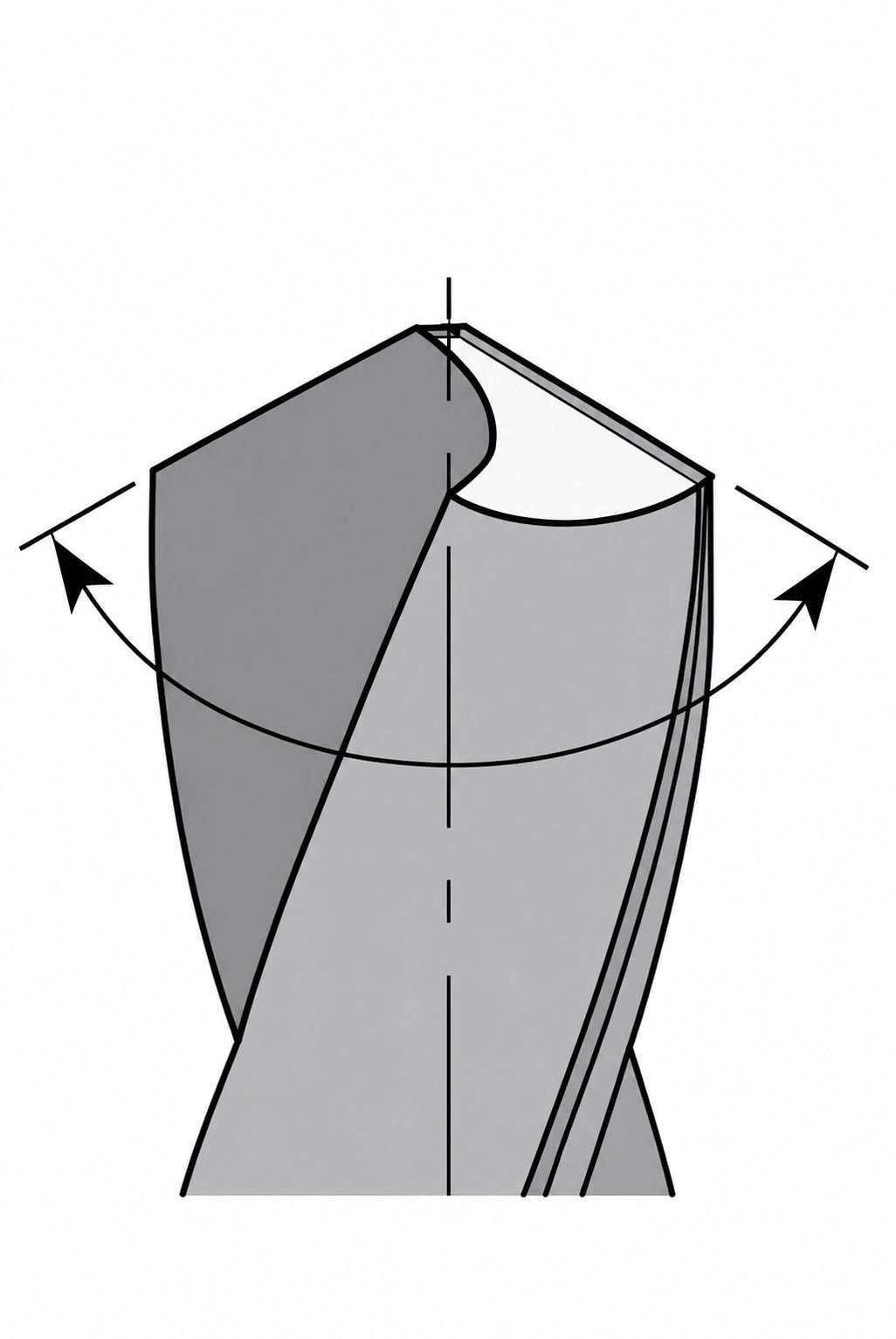
Drill point angle (Sharpening Handbook)
Drill point angle, sometimes called drill tip angle or drill bit angle, defines the geometry at the cutting end of the tool. Although it appears as a small feature, it directly influences how the tool enters the material, how chips form during penetration, and how cutting load is distributed across the drill point.
Different point angles are used because materials respond differently during CNC drilling, especially when chip behavior, heat generation, and hole quality become production concerns.
Simply put: the drill point angle is the included angle formed between the two primary cutting edges at the tip of a drill bit.
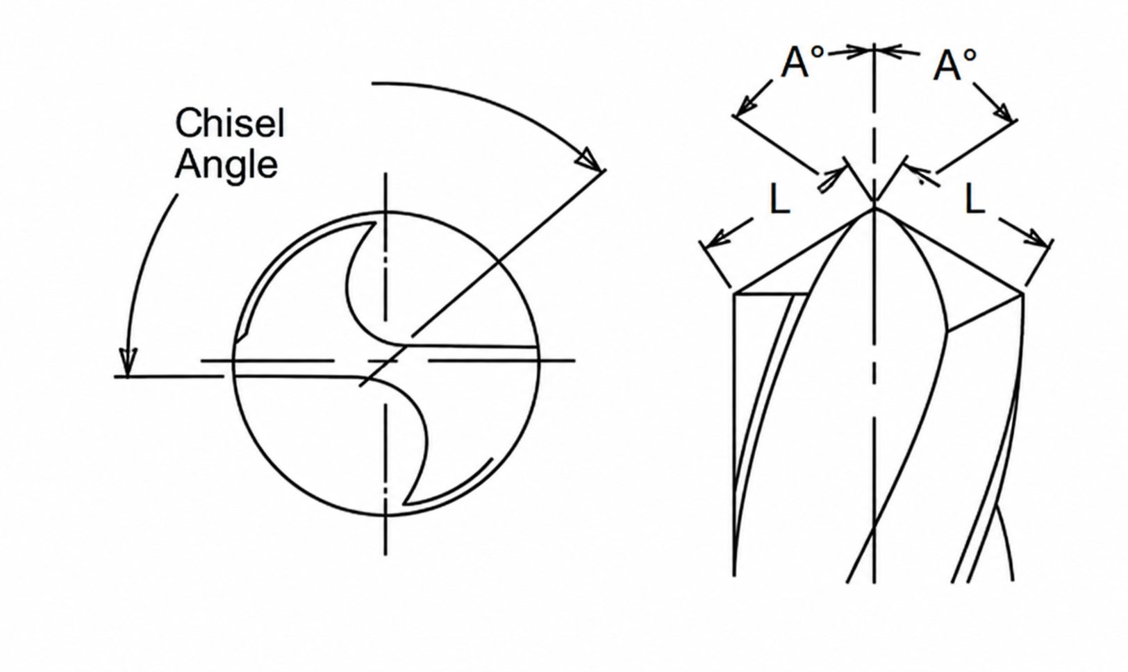
How Drill Point Angle Is Measured
The measurement is taken across the drill tip by evaluating the angle created where the two cutting lips meet at the center. Standard twist drills are commonly manufactured with point angles such as 90°, 118°, 135°, and 140°, although specialized drilling applications may use different geometries.
A smaller point angle creates a sharper tip with a longer cutting edge engagement near the center. In contrast, a wider point angle produces a flatter tip profile and distributes cutting action across a larger portion of the cutting edge.
During tool inspection, point angle is usually checked with drill gauges, optical measurement systems, or tool presetting equipment. Production shops often verify this geometry after regrinding because even small variations can alter hole entry behavior and wear patterns.
What Is the Standard Drill Bit Angle?
The answer is usually 118°.
Pick up a standard HSS twist drill from a maintenance cabinet, a tooling cart, or a general-purpose drill index. Most will have a 118° point.
The reason is practical rather than technical.
A shop running aluminum in the morning and low-carbon steel in the afternoon rarely wants to swap drill geometry every few hours. A 118° point handles both reasonably well. Not perfect. Usually good enough.
Once stainless steel enters the picture, things change.
Drill pressure builds near the center. Heat rises quickly if feed is inconsistent. Many manufacturers move toward 135° split-point drills because they start more predictably and tend to wander less during entry.
A 90° point exists too, although far fewer machinists see it in day-to-day production. It shows up around thin material, specialty tooling, and a handful of drilling operations where fast penetration matters more than tool life.
That's why asking for the "standard drill bit angle" usually leads to one answer:
118°.
Asking for the best drill point angle is a different question entirely.
Drill Point Angle vs Helix Angle
Drill point angle and helix angle are often discussed together, yet they control different aspects of drilling performance. The point angle governs how the drill penetrates the material, whereas the helix angle mainly guides chip evacuation through the flutes after material removal begins.
| Parameter | Drill Point Angle | Helix Angle |
|---|---|---|
| Location of the tool | Drill tip | Fluted section of the drill |
| Primary function | Establishes cutting geometry during penetration | Guides chip movement away from the cutting zone |
| Typical values | 90° to 140° | 15° to 40° |
| Direct influence on drilling | Hole entry behavior and cutting load distribution | Chip evacuation and flute performance |
| Relationship with chips | Influences initial chip generation | Influences chip removal after formation |
| Influence on thrust load | High | Limited |
| Influence on hole entry accuracy | Significant | Indirect |
| Common material consideration | Selected according to material hardness and drilling conditions | Selected according to chip type and material behavior |
| Wear a concentration area | Cutting lips with a chisel edge | Flute surfaces and cutting-edge support zones |
Although both geometries contribute to drilling performance, engineers usually evaluate point angle first when addressing penetration behavior, hole quality concerns, and material-specific drilling requirements.
Why Drill Point Angle Matters
Drill point angle defines the tip geometry that first contacts the material during drilling. That first contact zone sets the condition for penetration, chip initiation, and load distribution across the cutting edges. Changes in this geometry show up in entry stability, chip shape, tool wear location, and hole consistency during production.
Different materials respond differently to the same point geometry. Soft metals, stainless steels, and cast irons each produce distinct cutting behavior at the drill tip, which is why multiple point angles exist in standard CNC tooling practice.
Cutting Forces During Drilling
Cutting forces concentrate at the drill point during entry. The shape of the point controls how this force spreads across the cutting lips and center zone.
Wider point angles spread the load across a larger cutting edge area. This reduces force concentration at the center and supports drilling in materials that resist penetration. Sharper point angles place more load near the center region, which increases entry resistance and places higher demand on axial feed control.
Force imbalance between cutting lips often appears when grind quality or tool alignment is inconsistent. This shows up as uneven hole entry and slight deviation in hole formation, especially in deeper drilling operations.
Heat Generation and Chip Evacuation
Heat develops at the contact zone between the cutting edges and the material. Point geometry changes chip shape at the moment of formation, which affects how heat is carried away from the cutting area.
Sharper point angles generate thinner chips at entry, but chip flow can remain continuous in ductile materials. This keeps heat concentrated near the tip for longer durations.
Wider point angles often encourage shorter and thicker chip formation, particularly in tougher materials, although chip shape is also influenced by feed rate, helix geometry, and material properties. This changes heat distribution along the cutting edge and reduces localized thermal concentration at the center.
Chip evacuation becomes more sensitive in deep holes where flute space limits flow. In such cases, chip packing can interrupt cutting continuity and raise the temperature near the drill point.
Tool Wear and Tool Life
Wear begins at the drill point due to direct contact with uncut material during penetration. The location and progression of wear depend on point geometry and material response.
Wear often begins near the chisel edge because cutting speed approaches zero at the drill center. This region becomes a frequent wear zone during repeated production cycles.
Wider point angles shift wear toward the cutting lips. This spreads the load across a larger area but increases edge exposure during sustained cutting in abrasive materials.
Wear patterns also change with chip behavior. Poor chip breakage increases rubbing at the cutting edges, which accelerates flank wear and shortens tool life.
Impact on Productivity and Machining Efficiency
Drilling output depends on how consistently the tool maintains cutting conditions across repeated holes. Point geometry affects entry behavior, chip control, and stability during full-depth drilling.
Sharper geometries allow faster entry in softer materials but show faster wear in tougher alloys. This leads to more frequent tool changes in production runs involving harder steels.
Wider geometries support more stable cutting in resistant materials, but penetration speed decreases in free-cutting metals due to increased edge contact area.
Chip flow stability also influences cycle continuity. When chips exit cleanly, drilling remains steady. When chips accumulate in the flute, cutting becomes inconsistent and slows down the operation.
Common Drill Point Angles and Their Applications
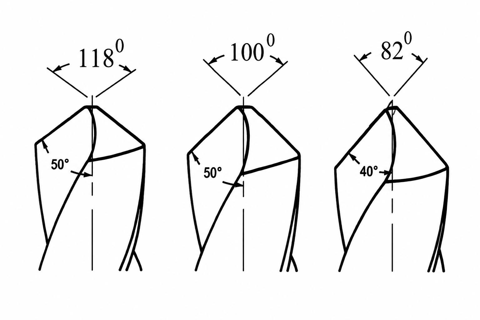
Illustration of drill point angles (ResearchGate)
Drill point angles are standardized across machining practice. Each angle supports a different cutting condition at the drill entry, especially when materials respond differently to penetration and chip formation. Selection is usually linked to material type and drilling stability during production use.
90° Drill Point Angle
A 90° point forms a sharp tip with a short contact zone at entry. The drill engages the material quickly, which works well for thin sections and softer materials.
90° point angles are less common in general-purpose drilling and are typically reserved for thin materials, countersinking-related operations, or specialized applications. In harder steels, the center region wears faster because the load stays concentrated near the tip.
118° Drill Point Angle
The 118° angle is the standard choice in general machining setups. It performs well across mild steel, aluminum, and brass. Entry remains steady without excessive force buildup, which helps in mixed production environments where material changes occur between batches.
Most job shops keep this geometry as the default because it handles a wide range of drilling conditions without special adjustments.
135° Drill Point Angle
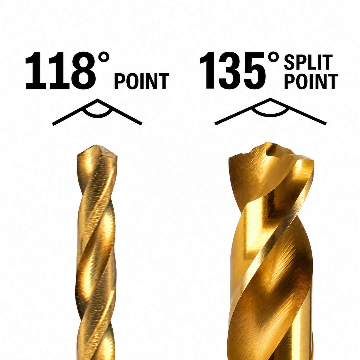
118° vs 135° drill point angles - (Punchlist Zero)
A 135° point is used when materials resist penetration more strongly. It reduces load at the drill center and supports stable entry in stainless steel, alloy steels, and work-hardening grades. Chip formation becomes shorter, which helps maintain more controlled evacuation in production drilling.
Split-point variants are commonly used with this geometry to reduce walking at the start of the hole. In production tooling, 135° drills are frequently combined with split-point grinding, making it difficult to separate the influence of point angle from the influence of point thinning.
Specialty Angles for Advanced Applications
Non-standard point angles appear in applications where standard geometries do not maintain stable drilling conditions. These include aerospace parts, composite stacks, and deep-hole work.
These tools are designed to adjust entry behavior and chip shape based on material response, especially when heat, chip packing, or surface condition becomes difficult to control.
Drill Point Angle Comparison
| Angle | Typical Use | Material Range | Entry Behavior | Chip Pattern | Notes |
|---|---|---|---|---|---|
| 90° | Thin sections, light drilling | Soft metals, plastics | Fast entry, sharp contact | Longer chips in ductile metals | Higher center wear in hard materials |
| 118° | General machining | Mild steel, aluminum, brass | Stable and balanced entry | Medium chip length | Common workshop standard |
| 135° | Harder materials | Stainless steel, alloy steel | Controlled entry, lower load | Short chips | Often used with a split point |
| Specialty | Aerospace, composites, deep holes | Application-specific | Controlled entry behavior | Designed chip control | Custom geometry based on the process |
Each angle is chosen based on how the drill enters the material and how stable the cutting condition remains during continuous drilling.
Choosing Drill Point Angles for Different Materials
Drill point angle selection follows material behavior at the drill entry. Each material reacts differently to penetration. Some cut freely, while others resist and generate a higher load at the center of the drill tip. Point geometry is adjusted to keep drilling stable and prevent early tool damage.
Aluminum and Non-Ferrous Metals
Aluminum and non-ferrous metals allow easy cutting at the drill point. Entry stays smooth, and chips form continuously.
A 118° point angle is commonly used because it keeps the entry stable without increasing the load at the center. In thin sheets, a 90° point may be used for quick penetration, but chip control becomes less stable in deeper holes.
Chip evacuation becomes more important than cutting force in long drilling operations with aluminum parts.
Carbon and Alloy Steels
Carbon and alloy steels increase resistance at the drill center during entry. The cutting edge carries more load compared to aluminum.
A 118° or 135° point is used depending on hardness. 135° is preferred when the material is harder or when tool wear appears early at the drill tip.
With steel, wear often starts near the center edge before spreading along the cutting lips.
Stainless Steel and Heat-Resistant Alloys
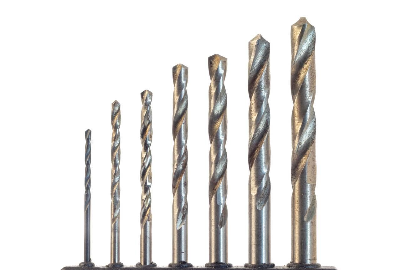
Hardened steel drill bits in a set of different sizes (Alamy)
Stainless steel creates higher entry resistance and uneven chip formation. The drill tip experiences a concentrated load during the initial cut.
A 135° point angle is commonly used to reduce center pressure. Split-point drills are also used to improve centering at the start of drilling.
Without proper geometry, the drill can show entry wandering and early edge wear in repeated operations.
Plastics and Composite Materials
Plastics and composites react based on structure rather than hardness alone. Soft plastics cut easily, but reinforced layers behave differently.
A 90° or modified point may be used for soft plastics to support clean entry. For reinforced plastics and composites, wider angles help reduce edge damage and avoid material separation at the hole boundary.
Layered composites need controlled entry to prevent lifting or separation at the exit side of the hole.
How Drill Point Angle Affects Hole Quality
Hole quality depends on how the drill tip behaves during entry and full-depth cutting. Drill point angle sets the initial contact condition, which then influences straightness, edge condition, internal surface, and size stability across repeated holes.
Hole Straightness and Positional Accuracy
Drill point angle affects how the drill centers at entry. A stable entry helps the drill follow the intended path through the depth of cut.
A 118° point usually stays balanced in common materials and supports steady tracking. A 135° point reduces initial push in harder steels, which helps reduce entry shift. When the drill struggles to center, the hole can start slightly off position and continue that deviation through the full depth.
Tool condition and grinding symmetry also play a role, especially when both cutting lips do not engage evenly.
Burr Formation at Hole Entry and Exit
Burrs form when material does not separate cleanly at the edge of the hole. Drill point angle influences how force exits the material.
Sharper points can increase exit burr in ductile metals due to higher penetration pressure. Wider angles reduce this effect by spreading the load across the cutting lips.
Exit burr is more visible in soft aluminum and stainless steel sheets, where the material tends to deform before breaking.
Surface Finish Inside the Hole
Internal surface finish depends on chip flow along the cutting edges. Drill point angle affects how chips form and move away from the cutting zone.
A stable angle produces consistent chip flow, which leaves smoother internal walls. If chip flow becomes uneven, the drill rubs instead of cutting, leaving visible tool marks inside the hole.
In stainless steel, surface marks are more noticeable when chip evacuation slows down during deep drilling.
Dimensional Consistency in Production
In repeated drilling cycles, point angle stability affects how consistent the hole size remains across batches.
A stable geometry keeps cutting load predictable, so hole diameter variation stays within a narrow range. If the drill wears faster at the center or lips, the hole size begins to drift.
This variation becomes more visible in high-volume production, where the same tool runs for long cycles without regrinding.
In production machining, drilling issues are often linked to the interaction between tool geometry, material behavior, and process parameters rather than a single factor alone. A drill point angle that performs well in aluminum may create excessive thrust load or unstable chip formation in stainless steel.
For parts with deep holes, tight positional tolerances, or difficult-to-machine alloys, JLCCNC reviews drilling requirements during process planning to identify potential tooling and machining risks before production begins.
Upload your CAD file to receive a manufacturing review and quotation.

Precision CNC Machining Service
Professional manufacturing, fast turnaround, and quality assurance.
Drill Point Angle vs Other Drill Geometry Features
Drill performance does not depend only on point angle. The tip geometry works together with helix shape, chisel edge form, and point design type. Each feature affects a different part of drilling, so changes in one feature often shift how the others behave during cutting.
Point Angle vs Helix Angle
- Point angle controls how the drill starts cutting at entry and how the load spreads at the tip.
- Helix angle controls how chips move away from the cutting zone after they form.
- A stable entry from point angle still fails if chip evacuation is poor due to a wrong helix design.
Point Angle vs Chisel Edge Geometry
Chisel edge geometry (Regal Cutting Tools)
- Point angle defines the outer cutting lips, while chisel edge geometry affects the center penetration zone.
- A blunt chisel edge increases thrust load even if the point angle is correct.
- Grinding the chisel edge properly reduces center pressure and improves entry stability.
Point Angle vs Split Point Design
- Point angle sets the basic tip shape, while split point modifies the center cutting action.
- Split point reduces walking by creating a self-centering effect at the entry.
- Even with the same point angle, split-point drills perform better on hard or uneven surfaces.
Drill Geometry Interaction Summary
| Geometry Feature | Main Function | Effect on Drilling | Practical Impact | Common Issue if Incorrect |
|---|---|---|---|---|
| Point Angle | Entry cutting shape | Controls penetration and load spread | Affects hole start and wear distribution | Entry instability and tool wear |
| Helix Angle | Chip evacuation path | Moves chips out of the hole | Maintains cutting continuity | Chip packing and heat buildup |
| Chisel Edge Geometry | Center cutting zone | Controls thrust force at the center | Affects penetration pressure | High thrust and poor centering |
| Split Point Design | Center modification | Improves self-centering | Reduces drill walking | Off-center holes and a poor start |
Each geometry feature supports a different stage of drilling, so stable performance comes from matching all features instead of adjusting only the point angle.
How to Select the Correct Drill Point Angle
Drill point angle selection depends on job conditions and material response. Each factor changes how the drill starts cutting and how stable it stays through depth. The goal is consistent holes with controlled tool load.
Hole Depth Ratio (L/D)
When the hole depth increases, the drill stays engaged inside the material for a longer time. For deeper holes, wider point angles are often preferred because they can improve entry stability, although hole depth usually requires additional considerations such as chip evacuation and coolant delivery. In shallow holes, 118° is usually enough since tool support is not a major issue.
Material Hardness
Hard materials increase resistance at the drill tip, especially during entry. A 135° point helps reduce this entry pressure in steels and alloy grades. Softer materials like aluminum can use 118° or even 90° because cutting starts easily without high resistance.
Machine Rigidity
Less rigid machines allow more tool movement during entry. This can shift the hole position if the cutting load is high at the drill center. A wider point angle helps reduce sudden force at entry, so the drill stays more stable on lighter setups.
Chip Evacuation Requirement
Some materials produce long chips that do not break easily. If chips stay inside the flutes, drilling becomes unstable and heat builds up. Point angles that support shorter chip formation help keep chip flow clear, especially in deeper or enclosed holes.
Production Volume
In long production runs, tool stability becomes more important than cutting speed. Standard angles like 118° and 135° are used because they give consistent wear and predictable performance. This reduces tool changes and keeps output steady across batches.
Best Practices for Selecting Drill Point Angles
Drill point angle selection works best when it follows job conditions step by step. Material behavior, hole size, and production target all affect how the drill performs during entry and full-depth cutting. A structured selection approach reduces tool issues and keeps hole results consistent.
Start With Material Requirements
- Begin with how the material reacts at the drill tip during entry and cutting.
- Use 118° for general metals and 135° for harder steels where the entry load stays high.
Consider Hole Depth and Diameter
- Deep holes keep the drill engaged longer, so entry stability becomes more important.
- Wider point angles work better in deep drilling, while smaller diameters often use standard 118° geometry.
Match Drill Geometry to Production Goals
- High-volume work needs stable wear and predictable tool life across long runs.
- Standard geometries like 118° and 135° help maintain consistent output without frequent tool changes.
Verify Performance Through Trial Machining
- Initial test drilling helps confirm entry behavior, chip flow, and hole condition.
- Small adjustments in point angle or feed can improve stability before full production starts.
Conclusion About Drill Point Angle
Drill point angle decides how the drill behaves at entry and how the load spreads through the cutting lips. In shop use, small changes in this angle show up as entry shift, early edge wear, or chip congestion inside the flutes.
118° stays common in general steel and aluminum work because it keeps entry stable without extra setup changes. 135° is used in stainless steel and tougher alloys because it reduces pressure at the drill center and keeps the tool from loading up quickly during penetration. Short depth jobs tolerate more variation, while deeper holes expose angle mismatch through drift and chip packing.
In repeated drilling runs, the wrong angle shows up first as uneven wear at the center, then as size variation between holes in the same batch. Correct selection keeps the drill cutting in a predictable way across long production cycles.
At JLCCNC, drilling work is reviewed based on material, hole depth, and production run size before machining starts. This helps keep entry stable, reduce early tool wear, and maintain consistent hole results across prototype and production batches.
Precision CNC Machining Service
Professional manufacturing, fast turnaround, and quality assurance.
FAQ About Drill Point Angle
Q: What is the standard drill point angle?
The most common drill point angle is 118°. It is widely used in general machining because it performs well on materials like steel, aluminum, and brass without special setup changes.
Q: What is the difference between a 118° and a 135° drill bit?
A 118° drill bit has a more aggressive center cutting action, which works well for softer and general materials. A 135° drill bit reduces pressure at the center, so it performs better in harder steels and keeps the entry more stable.
Q: Which drill point angle is best for stainless steel?
A 135° drill point angle is commonly used for stainless steel. It reduces entry resistance and helps control heat and tool wear in work-hardening conditions.
Q: How does drill point angle affect hole quality?
Drill point angle affects how the drill enters and stays in position during cutting. A stable angle improves hole alignment, reduces burr formation, and keeps the internal surface more consistent.
Q: Does a larger drill point angle increase tool life?
A larger drill point angle can often improve tool life in many harder materials because it spreads the cutting load over a larger area. This reduces stress at the center of the drill and slows wear.
Q: What causes drill walking during drilling?
Drill walking happens when the drill does not center properly at the start of the cut. It is usually linked to an unsuitable point angle, uneven tool grinding, or lack of self-centering geometry.
Q: How do engineers select the correct drill point angle?
Engineers select the drill point angle based on material hardness, hole depth, and production requirements. Harder materials usually need 135° to reduce entry load, while general steels and aluminum often work with 118°. Deep holes also push selection toward wider angles to keep drilling stable through full depth. Chip behavior and tool wear patterns are checked to confirm if the chosen angle stays consistent during repeated drilling cycles.
Popular Articles
• End Milling Explained: Types, Uses & Best End Mills for Metal & Wood
• End Milling vs Face Milling: Key Differences, Tools & Applications
• CNC Tooling 101: Choosing the Right End Mills and Cutters
• How to Choose the Right Cutting Tool Material (CNC & Lathe Guide)
• A Complete Guide to Tool Wear Detection and Maintenance in CNC Machining
Keep Learning
CNC Probing Guide: How CNC Probe Systems Work, Applications, and Benefits
Key Takeaways About CNC Probing CNC probing is on-machine measurement that replaces or reduces manual setup and inspection steps. A CNC probing system combines a probe body, stylus, signal transmission, and controller integration to measure workpiece position, tool length, feature dimensions, and surface location. CNC probing solutions range from basic workpiece location routines on a manual machine to fully automated in-process verification in unattended manufacturing cells. CNC probing simulation le......
Drill Point Angle: Selection, Materials, and Drilling Performance
Key Takeaways About Drill Point Angle A 118° point is used most often in steel and aluminum jobs because it drills without special setup changes on standard machines. 135° points show up more in stainless and tool steel work since they keep the drill from pushing hard at the center during entry. In aluminum and similar ductile materials, chips often come out in long strands when the point geometry does not support breakage. Hole entry stays more consistent when the drill point matches the material ins......
Jig vs Fixture: Key Differences and Applications in Machining
(AI generated) Drilling jig with guide bushings and CNC machining fixture holding a metal workpiece on a machine shop workbench. If you ask three machinists to explain the difference between jigs and fixtures, you’ll likely get three different answers. It’s one of those things that gets mixed up constantly, especially by anyone who isn’t actually standing at the machine. But when you’re planning a setup, that distinction becomes critical. How you hold a part changes everything: alignment, repeatabilit......
Types of Taps: How to Choose the Right Thread Tap for CNC Machining
(AI generated) Close-up of a thread tap cutting internal threads inside a metal workpiece. Tap breakage during blind hole threading is one of the most common production disruptions. This guide explains the different types of thread taps used in CNC machining and provides practical selection advice based on hole type, material, and machining conditions. What Is a Thread Tap and How Tapping Works What Is a Thread Tap? A thread tap is a cutting tool used to create internal threads inside a pre-drilled ho......
CNC Tooling 101: Choosing the Right End Mills and Cutters
Introduction: The Unsung Heroes of CNC Machining In CNC machining, precision doesn’t start with the machine—it starts with the tooling. Choosing the right end mills and cutters determines not only the surface finish and dimensional accuracy but also the machining time, tool life, and overall production cost. Many machinists and engineers underestimate how much tooling affects performance. Whether you’re shaping aluminum, cutting stainless steel, or milling engineering plastics, the right CNC tool can ......
How to Choose the Right Cutting Tool Material (CNC & Lathe Guide)
If you've ever heard a cutting tool scream with chatter or watched an edge chip after just a few passes, you already know, the wrong tool material will wreck your part, your time, and your budget. Geometry matters, yes, but material is what defines whether that tool can survive under the pressures of real machining. This is especially true when comparing lathe cutting tools with modern cutting tools for CNC. Traditional lathes can get the job done, but they're limited by manual control, speed, and con......