Sheet Metal Prototype: Design Tips, Lead Times, and Cost Factors
13 min
- What Is Sheet Metal Prototyping
- When Sheet Metal Prototypes Make Sense
- Common Processes Used in Sheet Metal Prototype Fabrication
- Materials for Sheet Metal Prototyping
- Design Tips for Sheet Metal Prototypes
- What Affects Sheet Metal Prototype Cost and Lead Time
- Sheet Metal Prototyping vs CNC Machining vs 3D Printing
- Choosing a Sheet Metal Prototyping Service
- Sheet Metal Prototyping at JLCCNC
- FAQ
Sheet metal prototyping is used to produce early-stage metal parts. It allows engineers to test form, fit, and assembly before getting into full production. It is typically applied when designs involve bent features, intricate cut features, and assembled components that must be validated under actual manufacturing conditions.
Manufacturers typically use standard fabrication techniques. These include precision laser cutting, bending, and joining. Prototypes can usually be produced within a few days rather than weeks, but actual lead time depends on part complexity and material availability.
Typical dimensional accuracy of prototypes is ±0.1–0.2 mm for laser-cut and bent features, depending on material thickness, bend complexity, and part size. Therefore, these are used for most enclosure validation, mechanical fit checks, and functional testing.
This article explains:
- What sheet metal prototyping is and when it is used.
- Common fabrication processes for prototype parts.
- Practical design rules for bends and assemblies.
- How material, complexity, and quantity affect cost and lead time.
What Is Sheet Metal Prototyping
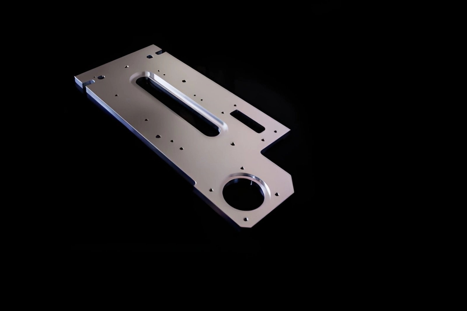
Automotive aluminium sheet metal part used for prototyping and testing fit and assembly. (Source: iStock)
Sheet metal prototyping is the process of making test parts from flat metal sheets using cutting, bending, and simple assembly methods to validate a design before production.
What Sheet Metal Prototypes Are Used For
- Check the part fit in the actual assemblies.
- Validate bend geometry and flat pattern accuracy.
- Test enclosure structure and panel alignment.
- Verify hole positions for fasteners and hardware.
- Evaluate strength and stiffness under load.
- Review surface finish and appearance.
- Support early-stage functional testing.
- Build small batches before production tooling.
When Sheet Metal Prototypes Make Sense
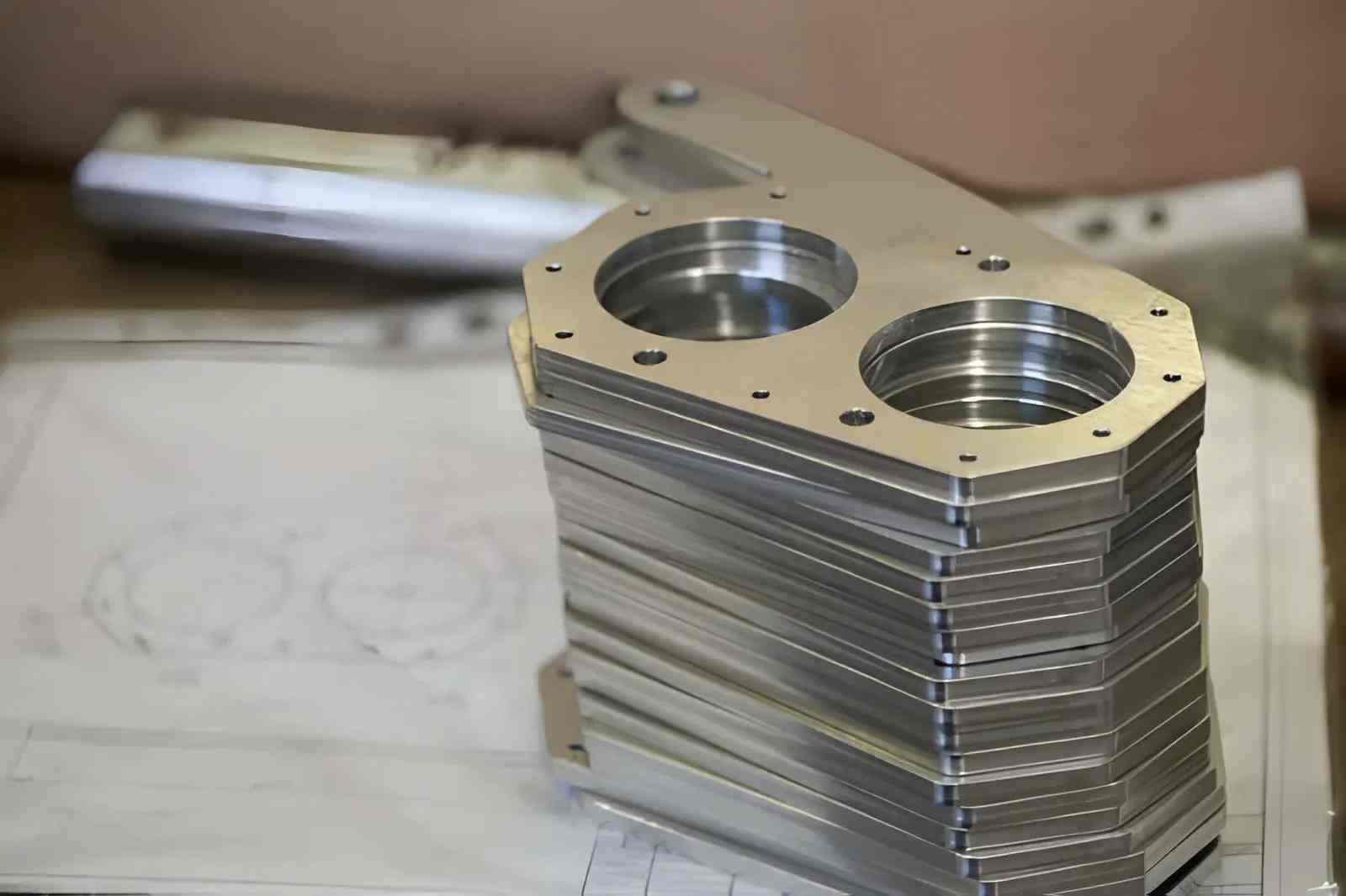
Stack of steel sheet metal prototype parts ready for assembly. (Source: iStock)
Sheet metal prototyping is used when part performance depends on cutting, bending, and assembly behavior. It is suitable when geometry and assembly conditions must be verified before production.
When the Final Product Will Be Made from Bent or Cut Metal
- Part includes bends, flanges, or formed edges.
- Flat pattern accuracy affects final geometry.
- Bend allowance and springback must be checked.
- Cut features influence strength or alignment.
When Form, Fit, and Assembly Need to Be Validated Early
- Parts must align with mating components.
- Hole positions must match fasteners or inserts.
- Assembly sequence needs verification.
- Clearance and interference must be checked.
When Low-Volume Builds Are Needed Before Production Tooling
- Batch size is typically below 50–200 parts.
- Design changes are expected between builds.
- Tooling cost is not justified at this stage.
- Parts are required for testing or pilot runs.
When Speed Matters but Full Hard Tooling Is Not Justified
- Lead time must stay within a few days.
- Laser cutting replaces stamping dies.
- Press brake forming replaces dedicated tools.
- Design iterations are expected after testing.
When Sheet Metal Is Not the Right Prototyping Method
- The part has complex 3D geometry and thick sections.
- Tolerance below ±0.05 mm is required.
- Internal features cannot be formed or accessed.
Common Processes Used in Sheet Metal Prototype Fabrication
Sheet metal prototypes are produced using cutting, bending, forming, and assembly operations to meet dimensional and functional part requirements.
Cutting Techniques for Prototype Sheet Metal Parts
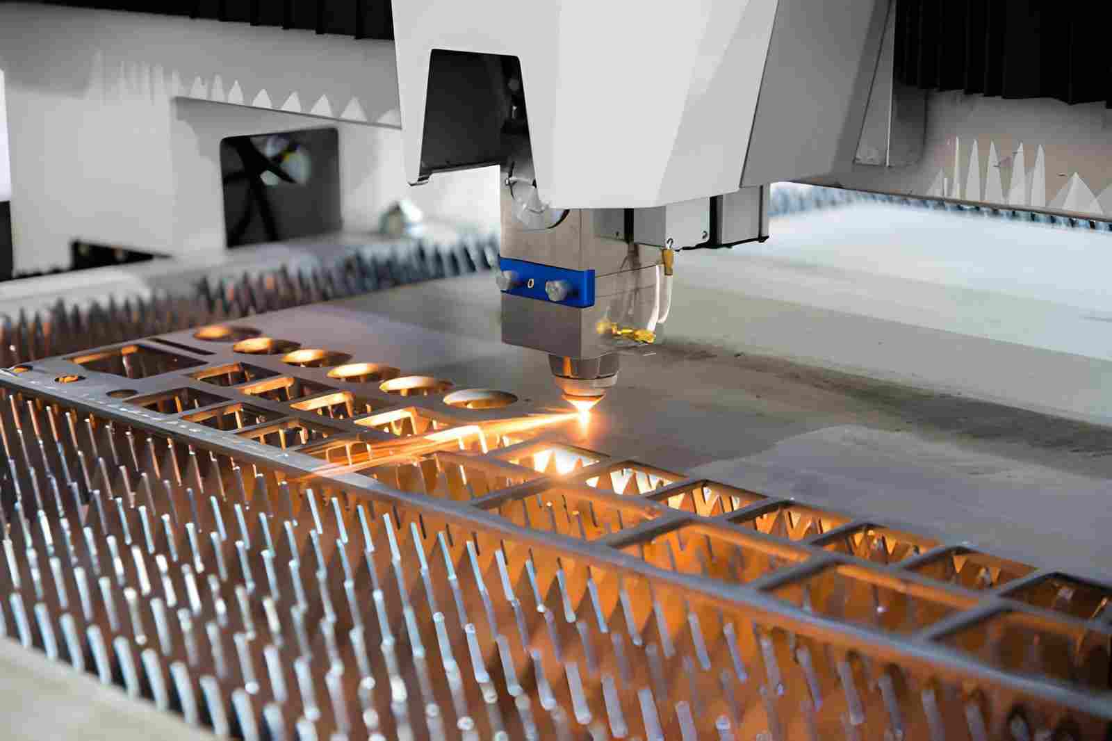
A metal sheet is being cut by a high-precision CNC laser machine. It creates clean, precise edges with minimal material distortion. (Source: iStock)
Laser Cutting: Laser cutting in sheet metal processing uses a controlled beam of light. It creates precise edges and cutouts, suitable for thin to medium sheets.
Waterjet Cutting: It uses abrasives to cut thicker sheets without heat distortion. This is suitable for complex profiles.
Turret Punching: It is efficient for repeated holes and simple shapes; faster for small batches.
Bending and Forming for Functional Sheet Metal Prototypes
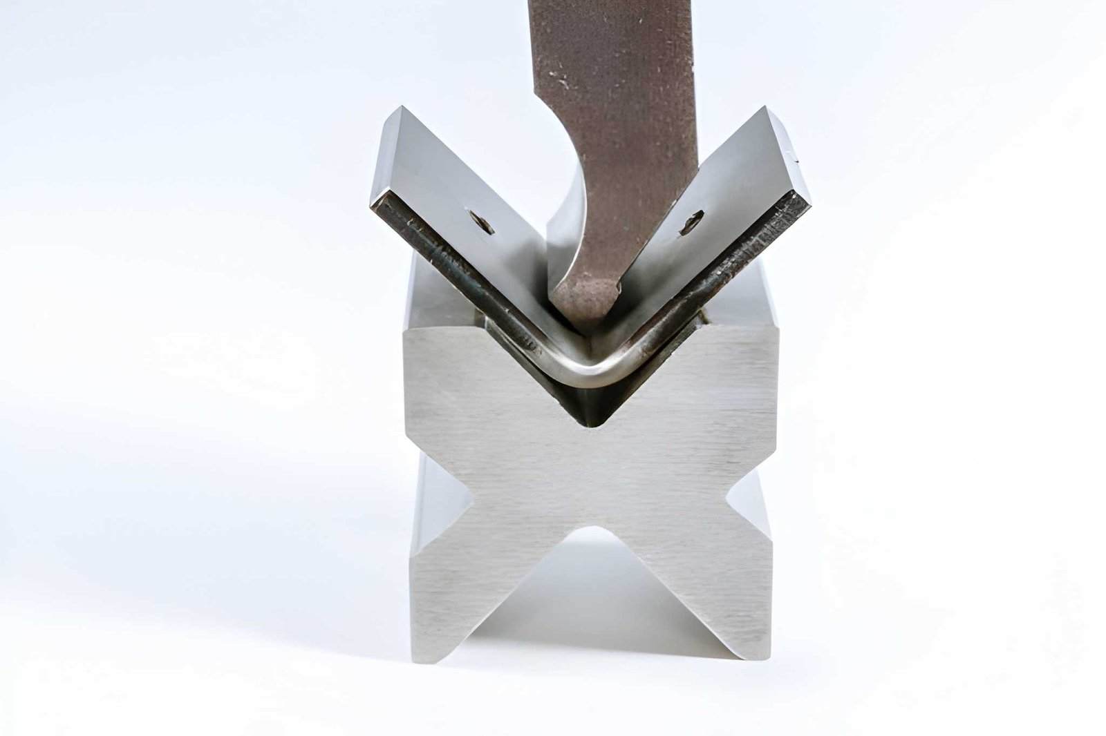
Hydraulic press machine bends a sheet metal prototype to shape precise components. (Source: iStock)
Press Brake: Bends edges and flanges accurately; adjustable for multiple angles.
Rolling: Creates curves or cylinders from flat sheets; suitable for enclosures or tubes.
Simple Forming Operations: Small flanges, tabs, or embosses using manual or mechanical tools. For a deeper explanation of these processes, see our guide on bending and forming techniques for sheet metal processing.
Joining Methods for Multi-Part Assemblies
Welding: Spot or MIG/TIG welding for structural connections.
Riveting: Mechanical joining for sheet overlays or brackets.
Fasteners: Screws, nuts, and bolts for removable assembly.
Surface Finishing
- Deburring edges after cutting.
- Light grinding or sanding to remove burrs.
- Optional coating, painting, or plating for improving appearance.
Materials for Sheet Metal Prototyping
Choosing the right material ensures that prototypes meet performance requirements while keeping costs under control.
Aluminum
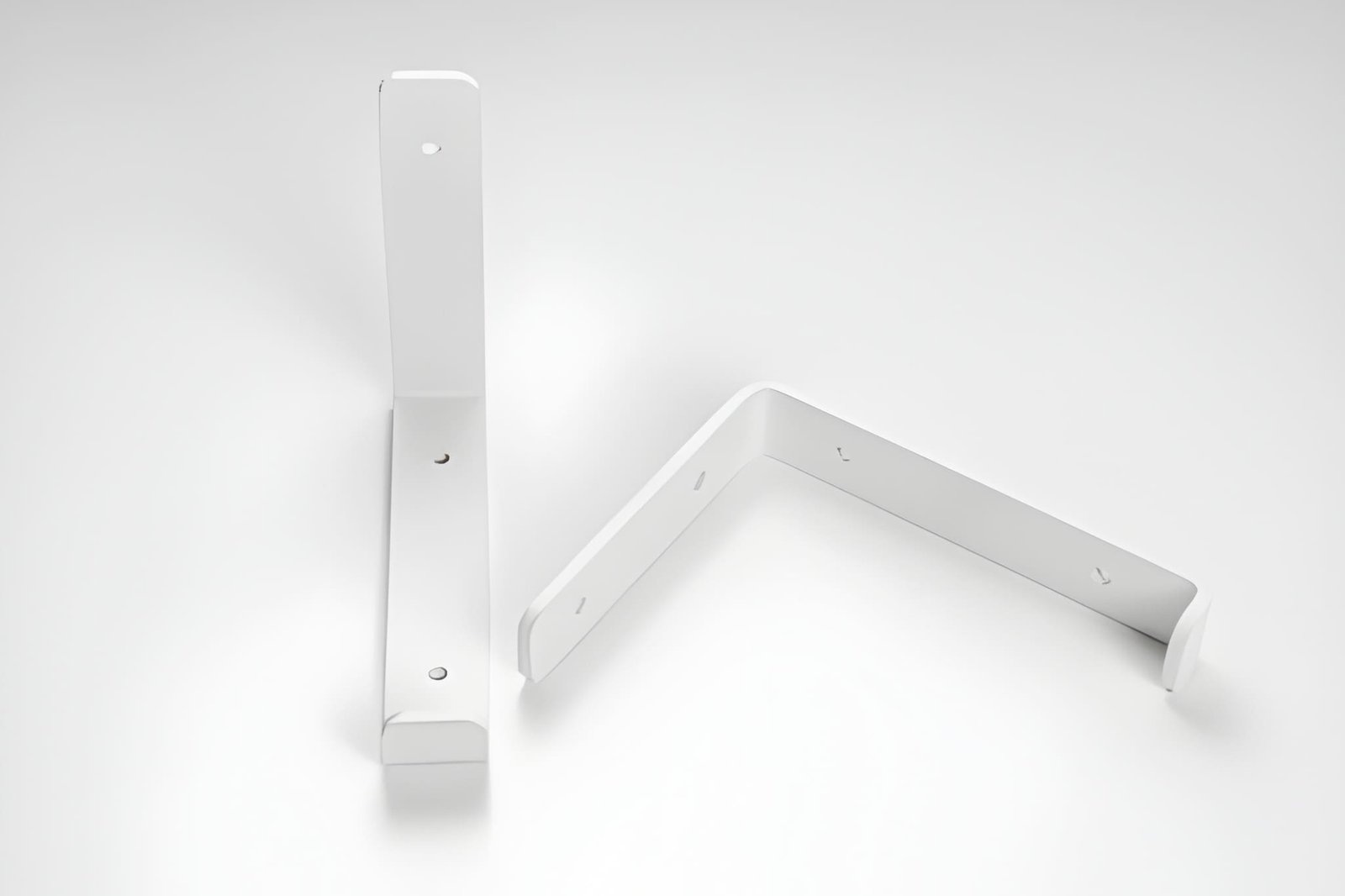
A bent sheet metal bracket on a white background, designed to support shelves. The part has a vertical flange for wall mounting and a horizontal flange. (Source: iStock)
- Lightweight and easy to form.
- Good corrosion resistance without coating.
- Suitable for bends, flanges, and thin sections.
- Common grades: 5052, 6061, 3003, 1100, 7075, 2024.
- Applications: Electronic enclosures, control panels, HVAC covers, heat sinks.
Stainless Steel
- Increased strength and corrosion resistance.
- It is more springy than aluminum; therefore, it tends to need a specific bend allowance.
- Applicable to functional prototypes that are subjected to moisture or other chemicals.
- Common grades: 304, 316, 310, 430, 409.
- Applications: Kitchen equipment panels, medical device brackets, chemical housings
Steel Alloy
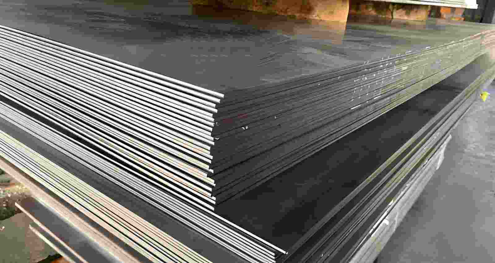
Multiple black steel plates stacked neatly on top of each other. Each plate has uniform thickness and smooth edges (Source: iStock)
- Strong and cost-effective.
- Easier to weld than stainless steel.
- Heavier than aluminum; may require thicker material for stiffness.
- Suitable for structural brackets or mechanical housings.
- Applications: Machine frames, support brackets, automotive chassis panels
Other Prototype Materials
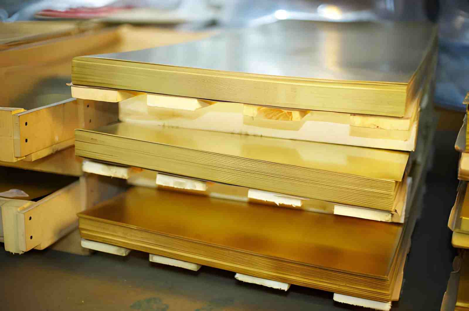
The image shows brass sheets stacked neatly in a factory setting (Source: iStock)
- Copper or brass for electrical or thermal applications
- Titanium has high-strength, low-weight functional parts.
- Special-purpose composite sheets are used to achieve stiffness and corrosion resistance.
- Applications: Heat sinks, battery enclosures, and aerospace brackets.
Design Tips for Sheet Metal Prototypes
Proper design ensures that prototypes are manufacturable and perform as intended. Adherence to bend, hole, and tolerance guidelines decreases rework and maintains short lead times.
Minimum Bend Radius Considerations
- A minimum inside bend radius of 1× material thickness is recommended for most metals, while softer materials like aluminum may require 1.5–2× thickness to prevent cracking.
- Aluminum also requires a larger radius than steel to avoid cracking.
- Sharp bends should be avoided, particularly when beyond press brake capability.
- Check springback, tool allowance, or adjust tool angles.
Hole and Slot Distance from Bends
- The minimum distance between bend lines and holes should be at least twice the material thickness.
- Do not put slots too near a bend to be distorted.
- In critical mounting holes, it is worth considering shifting them to the flat areas.
- Support tools adequately around edges to prevent burrs in bending.
Bend Relief and Corner Design
- Face corner cuts by adding bend relief cuts to avoid tearing in the forming process.
- Internal corners with a chamfer or small radius enhance the accuracy of the bends.
- In cases of several bends converging at a point, give adequate clearance.
- Embosses or work-hardened areas should be designed to remain flat where necessary.
Tolerances and Assembly Fit
- Standard sheet metal tolerance is ±0.1 to 0.2 mm for bends and cut features.
- Stack-up tolerances during part assembly; strategize on fastener clearance.
- Material springback should be accounted for when determining bending angles.
- In the multi-part assemblies, use alignment preceding the final joining activities.
What Affects Sheet Metal Prototype Cost and Lead Time
Prototype cost and lead time are shaped by material selection, geometry, and operations. Decisions made in design have a direct impact on fabrication effort and cycle time.
Material Type and Sheet Thickness
- Thick steel or stainless sheets require slower bending to prevent springback errors.
- Hard alloys increase tool wear and may need extra passes on the press brake.
- Aluminum bends easily. Its thin sheets can wrinkle or distort, and require careful handling.
- Rare or specialty sheets may need to be ordered in small quantities. This adds days to the lead time.
Number of Bends, Cut Features, and Forming Complexity
- Every bend adds setup and alignment checks; multi-bend parts often need multiple fixtures.
- Tight or compound bends may require slow feed to maintain accuracy, increasing cycle time.
- Deep cutouts, tiny tabs, or slots can be multi-passed or punched.
- Deep draws or rolling curves may need pre-bending or blank trimming, which is labor-intensive and time-consuming to check.
Secondary Operations and Surface Finishing Requirements
- Deburring sharp edges is important for assembly, but it can contribute between 5 and 10 min to each small part.
- Assemblies have to be welded, riveted, or bolted individually and checked.
- Finishes like powder coating, plating, or anodizing are surface finishes, and they need time to dry/cure, so the time to turn around is higher.
- Any redoing that stems from the misaligned holes or bends only adds to the cost and time directly.
Quantity and Revision Frequency
- The cost of single-part prototypes is very high, as every setup is used to make one part.
- Low-volume operations (less than 10–50 pieces) are efficient only when tooling and fixtures can be reused.
- New flat patterns, bend allowances, or cut files are often needed between iterations to help in design changes.
- Revision consolidation and batch planned build ensure the minimization of scrap and decreased delivery.
Sheet Metal Prototyping vs CNC Machining vs 3D Printing
Table 1: Sheet metal prototyping vs CNC machining vs 3D printing
Factor | Sheet Metal Prototyping | CNC Machining | 3D Printing (FDM / Resin / Metal) |
|---|---|---|---|
Lead Time | 2 - 7 days for single parts; multi-bend setups add hours | 1 - 5 days depending on stock, tool setup, and machining volume | Hours to days; depends on printer type, layer height, and post-processing |
Material Options | Aluminum, steel, stainless steel, copper, and brass | Solid blocks of aluminum, steel, plastics, and composites | PLA, PETG, Nylon, ABS, photopolymer resins, and some metal powders |
Geometry Capability | Limited to bends, cuts, and formed shapes; cannot make fully 3D internal cavities | High; can machine pockets, through-holes, threads, complex 3D features | Very high for complex or internal geometry; supports lattices, undercuts, and intricate cavities |
Mechanical Strength | High along the sheet plane; weak at bends if over-bent or improperly relieved | Very high; material is continuous and not layered | Layer-dependent; weaker along layer lines; metal prints approach bulk strength if sintered |
Surface Finish | Typically 0.5 to 2 µm Ra after bending and trimming; may need secondary finishing | High, 0.2 to 1 µm Ra achievable depending on tooling | Rough on FDM (~5 - 20 µm); SLA resin smooth (~1 - 5 µm); post-processing usually required |
Dimensional Accuracy | ±0.1 - 0.2 mm for bends and holes | ±0.01 - 0.05 mm depending on tooling and machine | ±0.05 - 0.2 mm for FDM; ±0.02 - 0.05 mm for SLA/metal prints |
Tooling & Setup | Press brake, laser/waterjet cutting, fixtures; multiple setups for complex bends | CNC machine, end mills, tooling, workholding; may require multiple setups for multi-face machining | Minimal: printer setup, support removal, post-cure for resin or sintering for metal |
Revision Flexibility | High; adjust flat pattern or bend sequence; minimal cost for first iteration | Medium; requires new toolpaths or stock adjustments; more setup time | Very high; digital file update and reprint; minimal setup cost |
Best Use Cases | Enclosures, brackets, panels, pilot batches, functional fit validation | Complex mechanical parts, mating features, precision prototypes | Complex internal structures, visual prototypes, and functional testing of geometrically intricate parts |
Limitations | Cannot produce thick 3D features; bends are limited by sheet thickness; springback must be accounted for | Material waste on large parts; setup time can add to cost; some internal cavities may need multi-axis machining | Layer adhesion and anisotropy; surface finish may require post-processing; limited high-strength materials |
Choosing a Sheet Metal Prototyping Service
The right supplier choice will save time, minimize errors, and enhance the quality of the prototypes. You must confirm the following before choosing the right partner.
Fast Quoting and Early DFM Feedback
- Supplier provides quotes within hours, not days.
- Early feedback on bends, hole placement, and material choice.
- Identifies potential manufacturability issues before cutting or forming.
- Reduces rework and shortens the prototype cycle.
Support for Multiple Iteration Rounds
- Can handle design revisions quickly without long delays.
- Maintains fixtures or tooling for repeatable bends.
- Supports incremental changes to flat patterns, holes, or bends.
- Enables functional testing of updated prototypes efficiently.
Fabrication Capacity and Reliability
- Has machines capable of the required sheet thickness and material type.
- Can handle multiple parts in parallel without affecting lead time.
- Maintains consistent quality across small batches.
- Offers predictable delivery for fast project schedules.
Sheet Metal Prototyping at JLCCNC
At JLCCNC, our sheet metal prototyping services focus on precision fabrication, flexible material choice, and quick iteration. JLCCNC ensures that your prototype development moves smoothly from the design phase to testing.
Fabrication Processes and Material Options
- Laser cutting, waterjet, and turret punching for precise cutouts.
- Press brake, rolling, and simple forming for functional bends.
- Joining via welding, riveting, or fasteners for multi-part assemblies.
- Materials: aluminum, stainless steel, copper, and specialty alloys.
- We support thin to medium sheet thickness for most enclosures and mechanical parts.
Rapid Sheet Metal Prototyping and Prototype Sheet Metal Parts
- Functional prototypes for testing bends, hole positions, and assembly fit.
- Able to produce brackets, panels, enclosures, housings, and custom mechanical parts.
Typical Lead Times and Support for Design Iteration
- Lead time is from 1 day, depending on your part complexity and batch volume.
- Quick adjustment for design changes between iterations (if needed).
FAQ
Q: What is sheet metal prototyping used for?
Sheet metal prototyping is used to test bends, cut features, and assembly fit before full-scale production. It helps engineers verify form, function, and mechanical alignment for panels, brackets, and enclosures
Q: What is the difference between sheet metal prototyping and sheet metal fabrication?
Sheet metal prototyping is used to make early sample parts for testing and review. Sheet metal fabrication covers the full process of making metal parts, from prototypes to production.
Q: How much does sheet metal prototyping cost?
The cost depends on material, thickness, complexity, quantity, and finishing. More bends, tighter tolerances, and added processing usually increase the price.
Q: What materials are commonly used for sheet metal prototypes?
Aluminum, stainless steel, carbon steel, copper, and brass are the most common materials. The optimal choice of material depends on its strength, weight, corrosion resistance, and bend behavior.
Q: How quickly can sheet-metal prototypes be made?
Parts with simple design features are typically made in 2 to 3 days. More complicated parts with multiple bends and assemblies typically take 5–7 days.
Q: What files are needed to get a prototype quote?
If you're developing a sheet metal prototype, uploading your CAD file to an online fabrication platform like JLCCNC can help you quickly evaluate manufacturability, cost, and lead time before production.
Q: How does sheet metal prototyping compare to CNC machining or 3D printing?
Sheet metal prototypes are best for bent or cut parts with functional assembly. CNC machining handles solid blocks and complex pockets with high accuracy. 3D printing is well-suited to intricate geometry and internal features but may lack mechanical strength.
Popular Articles
• Rapid Prototyping Guide: Processes Compared and How to Choose the Right Method for Manufacturing
• CNC Rapid Prototyping: Cost, Lead Time, Design Tips & Machining Service
• How is the Cost of CNC Machining Determined
• CNC machining solutions for DIY project designers
• The true cost of CNC machining services what are the main factors affecting price
Keep Learning
Rapid Prototyping Guide: Processes Compared and How to Choose the Right Method for Manufacturing
What Is Rapid Prototyping (AI generated) Various rapid prototyping parts including 3D printed, CNC machined, and sheet metal components on a workshop table. Rapid prototyping is a manufacturing approach that produces physical parts directly from CAD data within hours or days, enabling engineers to quickly validate design, fit, and function before full-scale production. Modern shops use several methods under this umbrella. 3D printing, CNC machining, and sheet processes all fall into the rapid prototyp......
Additive vs Subtractive Manufacturing: Differences, Advantages, and How to Choose the Right Process
Quick Comparison: Additive vs Subtractive Manufacturing Feature Additive Manufacturing Subtractive Manufacturing How it works Builds parts layer by layer Removes material from solid stock Best for Complex geometry, prototypes, low-volume production Precision parts, tight tolerances, production runs Design freedom Excellent, including internal channels and lattices Limited by cutting tool access Typical accuracy Lower as-built accuracy; post-processing is often required High dimensional accuracy direct......
OEM vs ODM: Key Differences, Benefits, and How to Choose
Key Differences at a Glance Between OEM and ODM Factor OEM Manufacturing ODM Manufacturing Design Origin Buyer provides the product design Supplier provides an existing design Product Control Higher control over specifications and development Less control over the core product design Engineering Input Requires more engineering and product development work Requires less technical involvement Customization Extensive customization options Limited to predefined modification options Intellectual Property I......
Large Part CNC Machining: Processes, Challenges, and Manufacturing Considerations
Key Takeaways About Large Part CNC Machining Large part CNC machining handles components where size itself introduces manufacturing challenges that standard machining doesn't face, thermal effects, deflection, workholding complexity, and dimensional control over long spans. Machine travel is one constraint but not the only one, part weight, spindle access, and workholding capability define what a machine can actually do with large components as much as the stated work envelope. Accuracy on large parts......
Low Volume CNC Machining: Small Batch Production Strategies and Manufacturing Guide
Key Takeaways About Low Volume CNC Machining Low volume CNC machining is typically used for production runs ranging from a single part to roughly 1,000 units, without the tooling investment required by molding or casting processes. Small batch CNC machining is often the most practical choice when designs are still evolving, demand is uncertain, or production quantities are too low to justify dedicated tooling. CNC machining can produce production-grade parts from aluminum, stainless steel, titanium, a......
On-Demand Manufacturing Process for CNC Production and Custom Parts
Key Takeaways CNC on-demand manufacturing is the most common implementation, machined metal and plastic parts produced from uploaded files with fast turnaround. The model reduces inventory investment, enables low-minimum-quantity orders, and allows design changes without scrapping committed production batches. On-demand production doesn't eliminate manufacturing cost, it shifts when that cost is incurred and removes the carrying cost of unsold inventory. The economics favor on-demand manufacturing at ......