Surface Roughness: Chart, Ra Values, Units & Applications
20 min
- Key Takeaways
- What Is Surface Roughness?
- Surface Roughness Parameters and Units
- Surface Roughness Chart
- What Affects Surface Roughness?
- Choosing the Right Surface Roughness
- Surface Roughness in CNC Machining
- Surface Roughness Applications
- Design Guidelines for Surface Roughness
- FAQs About Surface Roughness
- Conclusion About Surface Roughness
Key Takeaways
- Surface finish in machining directly influences how a part seals, slides, fits, and wears during service.
- Ra is the roughness value most commonly specified on manufacturing drawings.
- Even the same/similar machining techniques can produce different finishes after changing tooling, cutting data, and material.
- CNC Milling, CNC turning, grinding, and honing each leave their own surface pattern.
- A surface roughness chart gives engineers a practical reference during design and process planning.
- Specifying a finer finish than the application needs often increases machining time without improving the part.
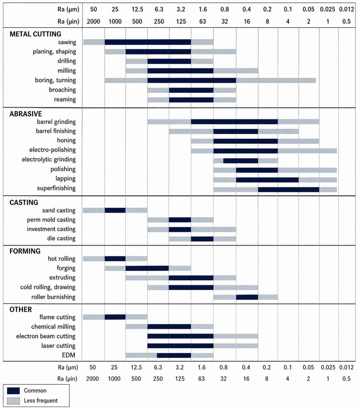
Surface roughness chart for different machining processes (ISO Finishing)
It is common to focus on dimensions during part inspection. If every measured size falls within specification, the component usually looks ready for assembly. Yet many machining problems appear after that stage because the surface finish does not match the drawing.
We have seen shafts that measured correctly but wore bearings sooner than expected. Sealing faces sometimes required rework because the machined surface was too coarse. In other jobs, parts spent extra time on surface grinding even though the application did not need such a fine finish.
Surface roughness helps engineers avoid these situations. Instead of treating it as another inspection value, they use it to select machining processes, plan finishing operations, and communicate the expected surface quality on the drawing.
In this guide, we explain the common roughness parameters, surface finish charts, Ra values, measurement units, and the machining processes used to achieve different surface finishes. You will also see how these values are applied during part design and production planning.
What Is Surface Roughness?
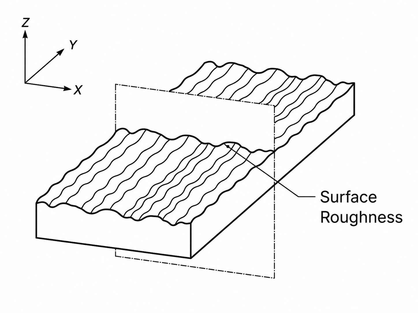
Machining Surface Roughness (Meetyou Carbide)
After machining, no surface comes off the machine completely smooth. A turning tool leaves feed marks, milling leaves cutter paths, and grinding produces its own finish. These marks are usually too small to notice without inspection, but they become important once the part begins to fit with another component. That is why engineering drawings include a surface finish requirement instead of leaving the final result to the machining process.
Surface roughness is the measurement of the fine irregularities left on a surface after a manufacturing process.
Surface Roughness vs Surface Texture
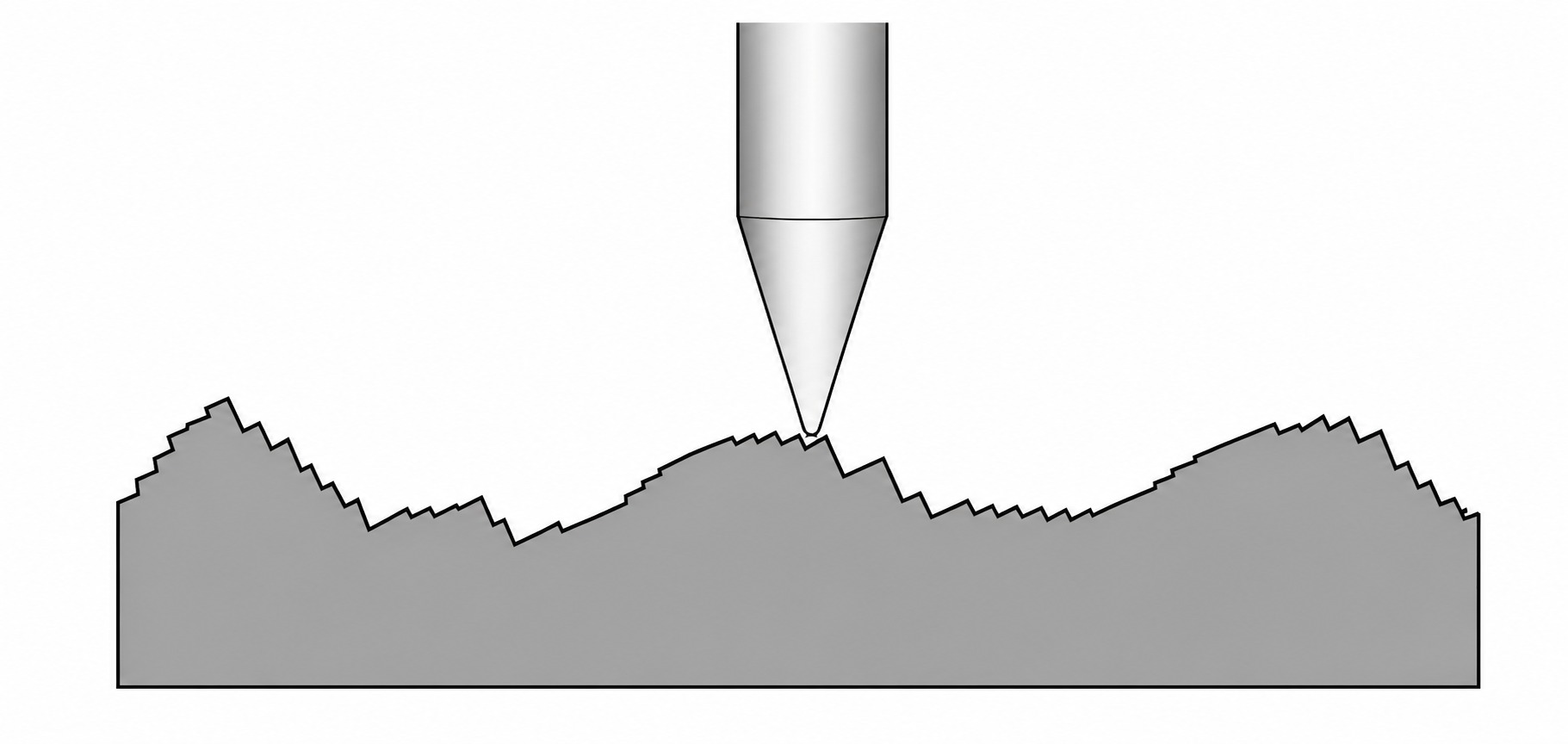
Surface Texture (EngineeringTechnology.org)
During drawing reviews, these two terms are often mixed. They are related, but they do not describe the same thing. Surface roughness looks only at the small irregularities created by the manufacturing process. Surface texture is the broader description used during inspection because it also considers the machining pattern and larger surface variations.
| Comparison | Surface Roughness | Surface Texture |
|---|---|---|
| What it describes | Fine irregularities left by machining | Complete condition of the manufactured surface |
| Engineering focus | Surface finish quality | Overall surface characteristics |
| Includes | Roughness parameters such as Ra and Rz | Roughness, waviness, lay, and surface defects |
| Typical use | Surface finish callouts on engineering drawings | Inspection and surface evaluation |
| Measured at | Microscopic level | Microscopic and larger-scale features |
| Relationship | One characteristic | Includes surface roughness as one element |
Why Surface Roughness Matters
Surface finish becomes noticeable during assembly, not while reading the drawing. A shaft may measure within size but still feel rough during bearing installation. A sealing face may pass dimensional inspection but fail a pressure test because the machining marks are too deep. The opposite also happens. Some parts receive extra finishing even though the application gains nothing from a lower Ra value.
Based on what we see in production, engineers usually match the roughness requirement to the job the surface performs. Sliding faces, sealing areas, bearing seats, and coating surfaces often need different finishes, even on the same component. Choosing the correct value helps the machine shop avoid unnecessary finishing while still producing a part that performs as expected.
Surface Roughness Parameters and Units
A single value does not describe surface roughness. Most engineering drawings specify Ra, so it is the value machinists see most often. However, some parts also call for Rz, Rq, or Rt, especially if the surface has a specific functional requirement. Knowing what these values represent helps during drawing review, machining, and final inspection because everyone is working from the same surface finish requirement.
Ra Surface Roughness
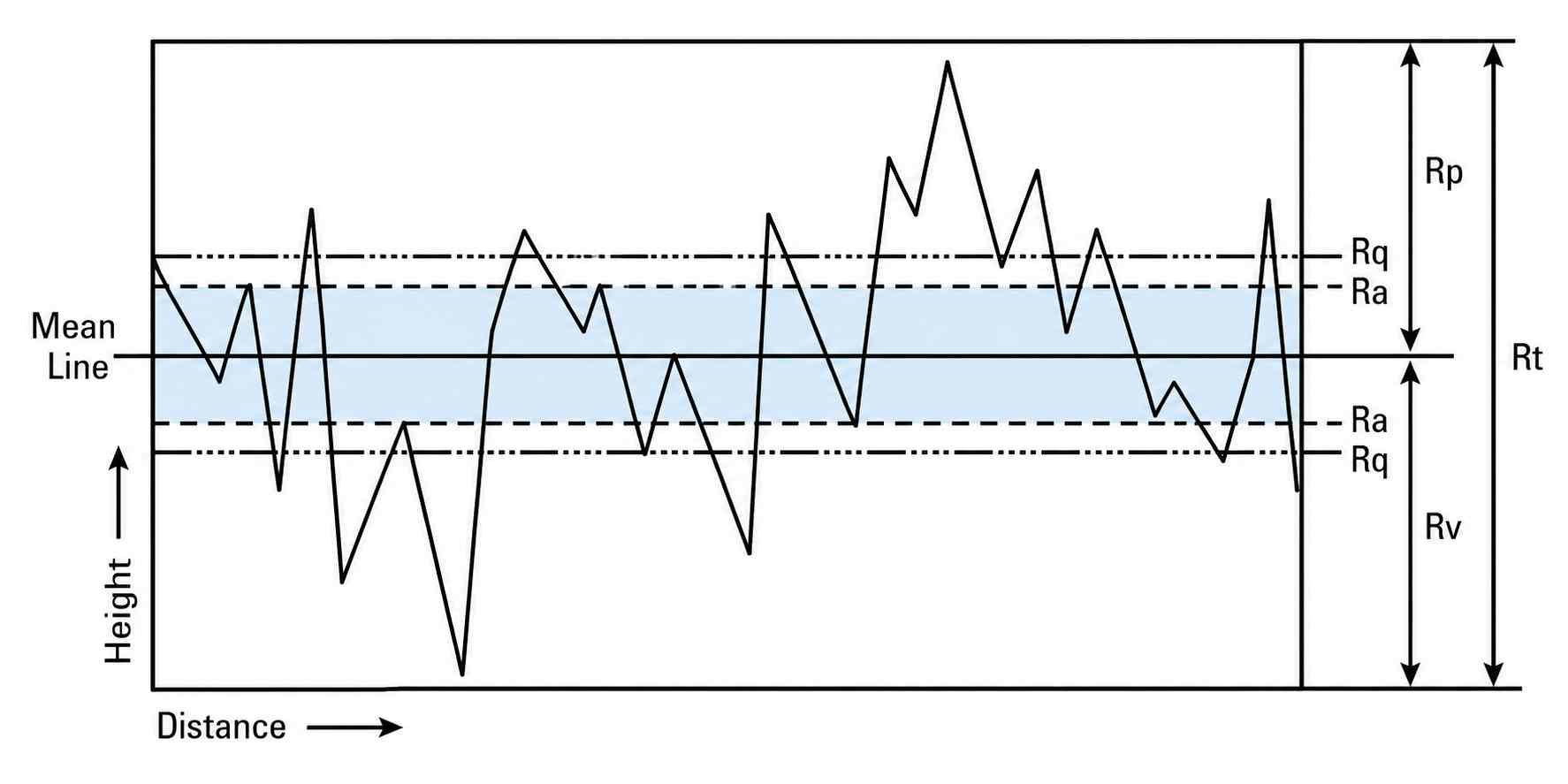
Surface Roughness Ra Inspection (AZo Materials)
Ra is the surface finish value engineers use most often. It represents the average height of the small peaks and valleys measured across a specified length. Because it gives a consistent reference, Ra is commonly added to machining drawings, CNC programs, and inspection reports.
You will find Ra values on bearing seats, sealing faces, machined housings, and many general-purpose components. For most production work, Ra provides enough information without requiring additional surface measurements.
| Ra Value | Typical Surface Finish | Common Applications |
|---|---|---|
| 12.5 μm | Rough machined finish | Sawing, rough machining |
| 6.3 μm | Standard machined finish | General milling and turning |
| 3.2 μm | Fine-machined finish | Standard CNC components |
| 1.6 μm | Smooth finish | Bearing seats, mating surfaces |
| 0.8 μm | Fine precision finish | Shafts, bushings, sealing faces |
| 0.4 μm and below | Very smooth finish | Grinding, polishing, precision components |
Other Common Parameters (Rz, Rq, Rt)
Ra does not describe every surface condition. Some components need additional measurements because the highest peaks and deepest valleys can influence performance.
- Rz measures the average height between the highest peaks and lowest valleys across several sampling lengths. It gives a better picture of prominent surface features.
- Rq is the root mean square value of the surface profile. Since it gives more weight to larger irregularities, it is often used for technical analysis and research.
- Rt measures the total height from the highest peak to the deepest valley within the evaluation length. Engineers may use this value for sealing surfaces, wear analysis, and other applications that are sensitive to extreme surface features.
Surface Roughness Units (μm and μin)
Surface roughness values are normally specified in micrometers (μm) and microinches (μin). Metric drawings usually use micrometers. By contrast, older drawings and many North American industries still use microinches.
Before comparing inspection results, always confirm the unit specified on the drawing.
| Unit | Full Name | Commonly Used In | Example |
|---|---|---|---|
| μm | Micrometer | ISO and metric engineering drawings | Ra 1.6 μm |
| μin | Microinch | Imperial drawings and some aerospace industries | Ra 63 μin |
Surface Roughness Chart
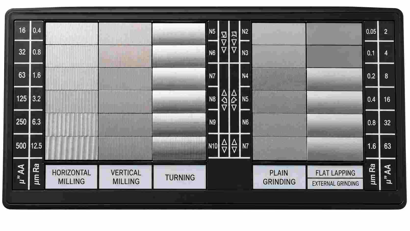
Surface Finish Chart (AN Precision Engineering)
Surface finish requirements vary from one part to another. A welded bracket does not need the same finish as a hydraulic spool and a bearing seat.
Selecting a surface finish starts with the function of the part rather than the lowest possible Ra value. The required finish should match both the engineering requirement and the capability of the planned manufacturing process.
The charts below provide a quick reference when selecting and specifying surface finish requirements.
Typical Surface Roughness Values
| Ra (μm) | Ra (μin) | Typical Finish | Common Examples |
|---|---|---|---|
| 0.025 | 1 | Optical-quality polished surface | Precision optical components |
| 0.05 | 2 | Mirror finish | High-precision molds |
| 0.1 | 4 | Super-finished | Gauge blocks, precision sealing faces |
| 0.2 | 8 | Fine polished | Valve seats, optical mounts |
| 0.4 | 16 | Precision ground | Bearing races, precision shafts |
| 0.8 | 32 | Fine machined | Bearing seats, hydraulic components |
| 1.6 | 63 | Standard CNC finish | Shafts, housings, mating surfaces |
| 3.2 | 125 | General machined finish | CNC milled and turned parts |
| 6.3 | 250 | Rough machining | Structural components |
| 12.5 | 500 | Coarse machining | Weld preparations, fabricated parts |
| 25 | 1000 | Very rough | Flame-cut and rough-machined surfaces |
| 50 | 2000 | As-cut surface | Castings and fabricated steel parts |
ISO Surface Roughness Grades (N1 - N12)
ISO roughness grades give engineers a standard way to specify surface finish on engineering drawings. Instead of writing long descriptions, many drawings simply use an N grade together with the required surface finish symbol.
| ISO Grade | Ra (μm) | Typical Manufacturing Method |
|---|---|---|
| N1 | 0.025 | Precision polishing |
| N2 | 0.05 | Fine polishing |
| N3 | 0.1 | Lapping |
| N4 | 0.2 | Honing, super finishing |
| N5 | 0.4 | Precision grinding |
| N6 | 0.8 | Fine grinding |
| N7 | 1.6 | Finish turning, finish milling |
| N8 | 3.2 | Standard CNC machining |
| N9 | 6.3 | Rough machining |
| N10 | 12.5 | Rough turning, rough milling |
| N11 | 25 | Heavy machining |
| N12 | 50 | Casting, flame cutting |
Surface Finish Achievable by Different Manufacturing Processes
The machining process usually determines the surface finish that can be achieved without additional operations. If the required Ra value is lower than the normal capability of the process, a secondary finishing operation is often added.
| Manufacturing Process | Typical Ra Range (μm) | Common Parts |
|---|---|---|
| Sand Casting | 12.5 - 50 | Cast housings, machine bases |
| Investment Casting | 1.6 - 6.3 | Precision cast components |
| Laser Cutting | 3.2 - 12.5 | Sheet metal parts |
| Turning | 0.8 - 6.3 | Shafts, pins, bushings |
| Milling | 0.8 - 6.3 | Plates, brackets, housings |
| Drilling | 3.2 - 12.5 | Standard holes |
| Reaming | 0.4 - 1.6 | Precision holes |
| Boring | 0.8 - 3.2 | Bearing bores, cylinders |
| Grinding | 0.2 - 1.6 | Bearing seats, tooling |
| Honing | 0.1 - 0.8 | Hydraulic cylinders |
| Lapping | 0.025 - 0.2 | Precision sealing surfaces |
| Polishing | 0.025 - 0.4 | Molds, optical and decorative parts |
Selecting a surface finish is not only about specifying an Ra value. The required finish has to match the machining process, material, and the function of the part. During process planning, JLCCNC reviews drawing requirements to determine whether the specified finish can be achieved through machining alone or whether an additional finishing operation is needed. Upload your CAD file to receive a manufacturing review and CNC machining quote.

Precision CNC Machining Service
Professional manufacturing, fast turnaround, and quality assurance.
What Affects Surface Roughness?
The same part may produce different surface finishes even when machined with the same CNC program. We see this during production after changing inserts, switching material batches, adjusting feeds, and moving the job to another machine. The drawing stays the same, but the finished surface does not. That is why machinists normally check the finish during production instead of assuming the programmed values will always produce the same result.
Material Properties
Not every material responds to the cutting tool in the same way. Some produce short, clean chips, while others leave a built-up edge on the insert and smear across the surface.
For example, free-cutting steels usually machine with a cleaner finish than stainless steel. Soft aluminum may also leave material on the cutting edge if chip evacuation is poor. That is why the machining parameters are often adjusted after changing the workpiece material.
Cutting Parameters
Small changes in cutting parameters are often visible on the finished surface. Feed rate usually changes the spacing of the tool marks, while cutting speed influences the heat at the cutting edge. Even the finishing allowance can change the appearance of the final pass.
In production, machinists commonly observe the following:
- Higher feed rates usually leave deeper feed marks.
- A light finishing pass often produces a cleaner surface.
- Built-up edge becomes more common with unsuitable cutting speeds.
- Stable chip evacuation helps prevent scratches on the machined surface.
Tool Condition and Machine Stability
It is not unusual for the surface finish to change halfway through a production run. The program stays the same, but the finished part starts showing different machining marks. In many cases, the problem comes from the machine setup instead of the CNC code.
A worn insert can leave a rougher finish long before the dimensions move out of tolerance. The same thing happens with loose fixtures, long tool overhang, spindle vibration, or chatter. Before changing feeds and speeds, machinists usually inspect the cutting tool and check whether the setup is still rigid. Many surface finish problems disappear after replacing the insert or improving the workholding.
Machining Process Selection
The selected machining process also changes the finish left on the part. A face milled surface will not have the same appearance as a turned shaft, and neither will match a ground component. Each process removes material differently, so the surface pattern changes as well.
During process planning, engineers usually start with the operation that best matches the feature. If a standard milling or turning operation can produce the required finish, there is little reason to add grinding, polishing, or another secondary process. Keeping the machining route simple often reduces production time while still meeting the drawing requirements.
Choosing the Right Surface Roughness
Selecting a surface finish starts with the function of the part, not the lowest possible roughness value. Every machined surface serves a different purpose, so the finish should match the application instead of using the same requirement across the entire component.
Match Surface Roughness to Functional Requirements
- Choose the surface finish according to how the feature will be used after machining.
- Apply finer finishes to bearing seats, sealing faces, sliding surfaces, and precision fits.
- Use standard machined finishes for surfaces that do not affect assembly or part performance.
- Specify roughness values only on surfaces that have a functional requirement.
Balance Surface Finish with Manufacturing Cost
- Lower roughness values usually require additional machining or finishing operations.
- Grinding, honing, polishing, or extra finishing passes increase production time.
- Use finer finishes only where they provide a functional benefit.
- Standard machining is sufficient for many non-critical surfaces.
Avoid Over-Specifying Surface Finish
- Avoid assigning the same surface finish to every face of the part.
- Tight finish requirements on non-functional areas increase machining time and inspection work.
- Review each surface individually during part design.
- Limiting fine finishes to critical features simplifies manufacturing while maintaining the required part quality.
Surface Roughness in CNC Machining
The machining process leaves its own pattern on the surface. Even if two parts meet the same dimensions, their finish can look different because the cutter moves differently, the cutting edge contacts the material differently, and the operation itself changes. During process planning, engineers usually consider the expected surface finish before selecting the machining method.
Milling Surface Roughness
Milled surfaces typically show cutter marks that follow the toolpath. Their spacing and appearance depend on feed rate, cutter diameter, insert condition, and step-over.
During finishing operations, machinists often reduce the feed rate, use a smaller step-over, and replace worn inserts before making the final pass. A rigid setup also helps reduce vibration marks that become visible on large flat surfaces.
Turning Surface Roughness
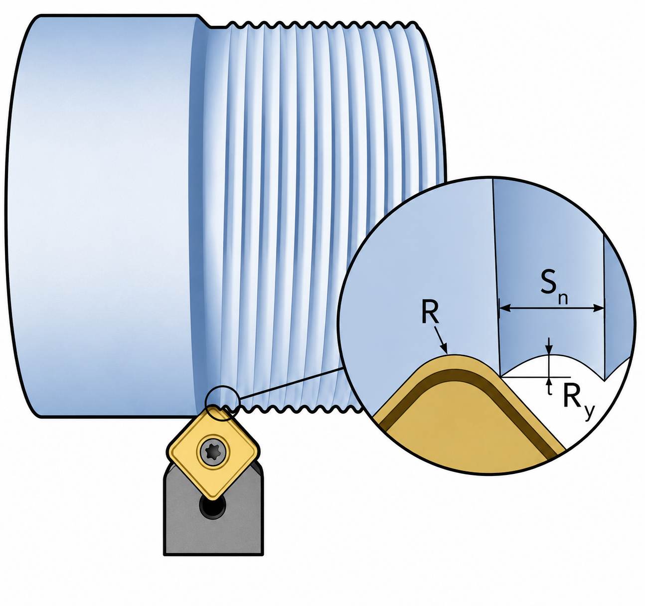
Surface finish when turning (Manufacturing Guide)
A turned surface forms a continuous spiral pattern around the part. Feed rate has a clear influence on this pattern, while insert nose radius and tool wear also affect the final finish.
In production, finish turning is usually performed as a separate operation after rough turning. A sharp insert, stable workholding, and correct cutting data often produce a cleaner shaft finish without adding another machining operation.
Grinding Surface Roughness
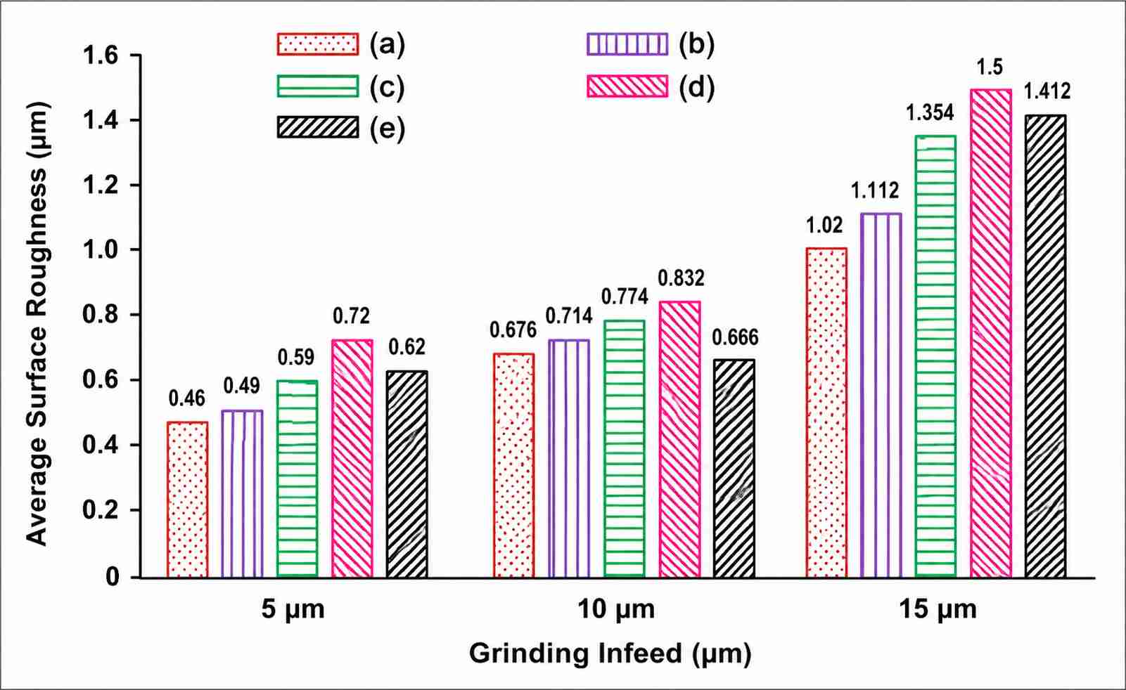
Average Surface roughness observed during different grinding infeeds (ResearchGate)
Grinding is commonly used when conventional machining cannot achieve the required surface finish. It removes a small amount of material while creating a much finer surface than standard milling or turning.
For bearing journals, precision shafts, and hardened components, grinding also improves surface consistency. Wheel condition and dressing intervals are checked regularly because a loaded wheel can quickly reduce surface quality.
Secondary Finishing Processes
Some components require additional finishing after machining. The process is selected according to the drawing requirements rather than applying the same finishing method to every part.
Common secondary finishing methods include:
- Honing: It is used for hydraulic cylinders and precision bores.
- Lapping: Lapping is optimal for sealing faces and gauge surfaces.
- Polishing: It applies to molds, optical components, and decorative parts.
- Superfinishing: It is suitable for bearing races and high-speed rotating parts.
These operations remove only a small amount of material, but they can improve the surface finish beyond what standard CNC machining typically produces while also reducing visible machining marks.
Surface Roughness Applications
Surface finish requirements change from one feature to another. A housing, shaft, sealing face, and optical component rarely share the same Ra value because each surface performs a different job. During design, engineers specify roughness only for the areas that influence assembly, movement, sealing, coating, inspection, and product quality.
Sealing Surfaces
A sealing face must be smooth enough for the gasket, O-ring, or seal to sit evenly against the surface. Deep machining marks can create small leak paths, while an extremely polished surface may reduce the sealing material's ability to grip.
For this reason, sealing faces usually receive their own surface finish callout instead of using the same finish as the rest of the part. Flanges, valve bodies, hydraulic manifolds, and pump housings are common examples.
Sliding and Bearing Components
Parts that slide against each other work best with a controlled surface finish. A rough surface can increase friction during operation, while unnecessary polishing adds machining time without improving the fit.
You will often see specific roughness requirements on:
- Bearing journals
- Shaft bearing seats
- Linear guide surfaces
- Hydraulic cylinder bores
- Bushing contact surfaces
These features normally receive a finishing operation that matches the drawing requirement.
Coating and Bonding Surfaces
Paint, powder coating, adhesive, and thermal spray coatings all sit on the surface produced during machining. If the finish is too rough, coating thickness may become uneven. If it is too smooth, some coating systems and adhesives may not bond as expected.
Before coating, many manufacturers machine the surface to the required finish and then complete cleaning or surface preparation before the next production step.
Optical and Precision Components
Some components require a surface finish beyond the capability of standard CNC machining. Camera mounts, optical fixtures, precision gauges, mold cavities, and measuring equipment often require grinding, lapping, polishing, or another finishing process to reduce visible tool marks.
In these applications, the drawing usually specifies both dimensional requirements and a much finer surface finish because both affect the finished component.
Design Guidelines for Surface Roughness
Although surface finish is often specified near the end of the design process, it can significantly affect the machining plan. A single Ra callout may add grinding, polishing, extra inspection, or another finishing operation. Before assigning a value, engineers usually check whether the surface actually needs additional finishing or whether the standard machining process already produces a suitable result.
Specify Only the Surface Finish the Part Requires
Not every face on a component needs the same finish. Some surfaces simply provide clearance or support, while others contact bearings, seals, mating parts, or coatings.
During drawing reviews, functional surfaces are normally identified first. These areas receive individual roughness callouts, while non-functional faces are often left with the finish produced by standard machining. This keeps the drawing simple and avoids unnecessary finishing work.
Use Standard Roughness Values Whenever Possible
Machine shops work with common Ra values every day. Using standard values makes process planning, inspection, and machining much easier.
Instead of requesting unusual finish values, engineers often select one that already matches the capability of turning, milling, grinding, or another planned operation. This approach also reduces unnecessary inspection because the required finish follows established machining practices.
Consider Manufacturing Capability Early
Surface finish is easier to plan before machining begins than after the first part reaches inspection. If the drawing asks for a finish that the selected process cannot produce, another operation may need to be added later.
For example, a part planned for standard milling may require grinding after the drawing is released. Reviewing the machining route during design helps avoid these production changes and keeps the process straightforward.
Communicate Surface Finish Clearly on Engineering Drawings
A roughness specification is only effective when it is interpreted consistently by design, manufacturing, and inspection teams. Missing symbols, unclear notes, or roughness callouts placed on the wrong surfaces often lead to questions during production.
Most engineering drawings become easier to interpret when:
- Surface finish symbols point to the exact machined surface.
- Only functional surfaces receive individual Ra values.
- Units remain consistent throughout the drawing.
- General notes define the default finish for unspecified surfaces.
- Special finishing requirements are identified separately from dimensional tolerances.
Clear drawings reduce back-and-forth between design, machining, and inspection teams, making production smoother from the first part onward.
Precision CNC Machining Service
Professional manufacturing, fast turnaround, and quality assurance.
FAQs About Surface Roughness
Q: What is surface roughness?
Surface roughness describes the small peaks and valleys left on a machined surface after manufacturing. Every machining process leaves its own pattern. Engineers use roughness values to specify how smooth a functional surface needs to be.
Q: What is Ra surface roughness?
Ra is the arithmetic average of the surface profile measured over the specified evaluation length. It is the most common parameter used on engineering drawings because it provides a simple way to specify and inspect surface finish.
Q: What are surface roughness units?
Surface roughness is commonly measured in micrometers (µm) and microinches (µin). Most ISO drawings use µm, while µin is still common on drawings that follow inch-based standards.
Q: What is a surface roughness chart?
A surface roughness chart is a reference table that compares Ra values, ISO roughness grades, machining processes, and common applications. Engineers and machinists use it to select a finish that matches both the drawing requirements and the planned manufacturing process.
Q: What is the difference between Ra and Rz?
Ra gives the average height of the surface profile across the measurement length. Rz represents the average maximum peak-to-valley height of the surface profile. Two surfaces can have the same Ra value but different Rz values because their surface profiles are not identical.
Q: Which machining process produces the best surface finish?
That depends on the required finish. Standard milling and turning produce good finishes for many components, while grinding, honing, lapping, and polishing are used for much finer surfaces. The process is usually selected according to the drawing requirements rather than using the finest finish on every part.
Q: How does surface roughness affect machining cost?
Lower roughness values often require slower cutting conditions, additional finishing passes, secondary operations, and extra inspection. If a standard machined finish already meets the drawing requirement, avoiding unnecessary finishing can reduce production time and overall cost.
Q: How do engineers choose the correct surface roughness?
Engineers usually start by identifying the functional surfaces on the part. Features used for sealing, bearing fits, sliding contact, and assembly often receive specific roughness values, while non-functional surfaces are left with the finish produced by the selected machining process. This approach keeps the drawing practical and avoids unnecessary machining.
Conclusion About Surface Roughness
A surface finish callout may look like a small note on the drawing, but it often changes the entire machining route. It can influence tool selection, cutting data, finishing operations, inspection, and even the time required to produce the part. That is why experienced engineers avoid assigning the same Ra value to every surface.
Instead, they identify the features that actually need a controlled finish, such as bearing seats, sealing faces, sliding surfaces, and precision fits. The remaining areas are usually left with the finish produced by the selected machining process. This keeps the drawing practical and avoids machining work that adds little value.
At JLCCNC, every drawing is reviewed before production to confirm that the specified surface finish matches the planned machining process. Upload your CAD file to receive a manufacturing review and CNC machining quote based on your engineering requirements.
Popular Articles
• Surface Finish in Machining, Types, Charts & Testing
• Anodizing vs. Hard Anodizing: The Differences in Surface Treatment Techniques
• Anodized Aluminum Colors: Options, Limits, and Real-World Results
• Explanation of different material surface treatment technologies in CNC machining
• How to choose between Laser marking and UV printing?
Keep Learning
Surface Finish in Machining, Types, Charts & Testing
What is Surface Finish in Machining? At its core, surface finish in machining refers to the small-scale irregularities left on the surface of a part after machining. These irregularities are typically grouped into three categories: Roughness: The fine, closely spaced deviations caused by the cutting process itself. Roughness depends heavily on feed rate, tool sharpness, and cutting speed. Waviness: Larger, more widely spaced variations caused by machine tool vibration, deflection, or thermal distortio......
CNC Machining Surface Roughness: A Practical Guide
Why Surface Roughness Matters in CNC Machining When we talk about CNC machining, precision isn't just about hitting the right dimensions, it’s also about how the surface feels and performs. Surface roughness describes the fine irregularities left on a machined surface, and it directly impacts how a part behaves in the real world. So, what is surface roughness? In simple terms, it's the measure of tiny peaks and valleys created by the cutting process. While they might look smooth to the naked eye, thes......
Optimizing Manufacturing Efficiency: A Guide to Computerized Numerical Control (CNC) Machining Surface Finishes
CNC Surface Finishes: Types, Costs, and How to Choose Quick Answer: Choose an as-machined finish when cost and dimensional stability matter most. Use bead blasting or brushing for a uniform cosmetic appearance, anodizing for aluminum corrosion resistance, hard anodizing for wear, and laser marking or UV printing for identification. Confirm material, tolerance, color, masking, and end-use environment before quoting. A CNC-machined part comes off the machine functional but rarely finished — tool marks, ......
Anodizing vs. Hard Anodizing: The Differences in Surface Treatment Techniques
Quick Answer: Choose Type II anodizing when corrosion resistance, color, and cosmetic appearance are the main requirements. Choose Type III hard anodizing when the part needs greater wear resistance and the coating thickness can be accommodated in the fit and tolerance plan. Confirm alloy, coating thickness, color, sealing, and critical dimensions before release. An aluminum bracket for an outdoor enclosure and a hydraulic cylinder rod both might get anodized — but specifying the same process for both......
How to Remove Anodizing from Aluminum Parts
Key Takeaways Chemical stripping is commonly used when anodizing needs to be removed from most or all of an aluminum part, but the process can also attack the underlying aluminum if it is not controlled. Mechanical removal works well for accessible areas but can change the surface texture and remove more base metal than intended. CNC machining gives better control when a defined anodized area needs to be removed from a precision part. Laser-based removal can be useful for controlled localized treatmen......
Anodizing Thickness: How Much Does It Add?
Anodizing Thickness and Dimensional Change at a Glance Feature Approximate dimensional effect One coated external surface +0.5 × coating thickness Outside diameter across two coated surfaces +1 × coating thickness Bore diameter with two coated walls −1 × coating thickness 60° thread pitch diameter Changes by about 4 × surface-growth amount, or about 2 × coating thickness under the 0.5× growth assumption Dimensional estimates below use the 0.5 × coating-thickness surface-growth relationship given in MI......