Metal Prototyping for Product Development: Manufacturing Methods, Material Selection, and Production Planning
19 min
- What Is Metal Prototyping?
- Common Manufacturing Methods for Metal Prototypes
- Choosing Materials for Metal Prototypes
- Metal 3D Printing vs Traditional Prototype Manufacturing
- Designing Metal Parts for Prototype Manufacturing
- Prototype Validation and Manufacturing Realism
- Lead Time, Cost, and Production Considerations
- Common Challenges in Metal Prototyping
- Where Metal Prototype Manufacturing Is Commonly Used
- Conclusion About Metal Prototyping
- FAQ About Metal Prototyping
Key Takeaways About Metal Prototyping
- Metal prototypes help check assembly fit, part movement, and design function before production starts.
- Physical prototype parts often expose issues that CAD files or models do not show during early design review.
- CNC machining is widely used because it produces functional parts from real production-grade metals.
- Material choice affects machining response, part weight, strength, and testing behavior during evaluation.
- Prototype quantity, dimensional requirements, and delivery targets influence process planning and manufacturing cost.
- Aluminum is commonly selected during early development because machining remains faster and more economical.
- Functional testing usually requires materials close to the final production alloy and condition.
- Secondary finishing and high-accuracy features increase machining time and prototype cost.
- Design revisions occur more frequently during prototype stages before production geometry becomes stable.
- Early manufacturability review helps reduce redesign work before low-volume manufacturing begins.
Metal prototypes are typically produced before tooling and production planning are finalized. At this stage, engineering teams use physical parts to evaluate assembly fit, feature interaction, machining feasibility, and structural behavior under real handling conditions.
Prototype revisions are common. Hole locations, wall thickness, support features, and mating geometry often change after the first physical evaluation. Discovering these problems early helps reduce redesign effort before low-volume or full production begins.
This article explains rapid prototyping from a manufacturing perspective, including CNC machining, sheet metal fabrication, metal 3D printing, material selection, and production planning considerations.
What Is Metal Prototyping?
Metal prototyping is the process of producing physical metal parts before production to evaluate fit, function, assembly behavior, and manufacturing feasibility.
Prototype parts help teams move beyond CAD models and drawings. A design may look complete on screen, but physical testing often reveals issues related to assembly access, part movement, wall thickness, fastening locations, and machining limits.
Functional vs Visual Metal Prototypes
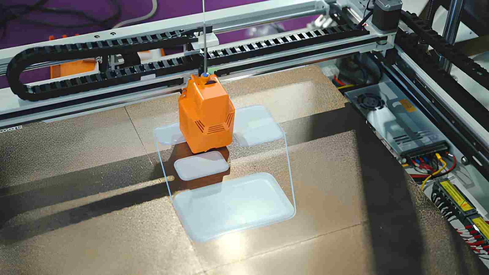
Advanced 3d printer machine operating in a modern innovation lab, an additive system for industrial prototyping and engineering - iStock
Not all prototypes are built for the same evaluation stage. Some prototypes are used to review shape, external dimensions, and overall presentation, while others are manufactured to behave closer to the final production component during testing.
Visual prototypes mainly support appearance review, external geometry checks, and presentation approval. Surface finish, visible quality, and external form usually receive more attention than structural performance. Functional prototypes usually use production-grade materials and tighter dimensional control because the parts are evaluated under assembly load, motion, thermal variation, and real operating conditions.
Why Metal Prototypes Are Used Before Production
Production modifications become harder once tooling, fixtures, machining strategy, and process planning are already established. Prototype stages allow engineering teams to identify manufacturing and assembly problems while design revisions are still relatively easy to implement.
Prototype parts are commonly used to verify assembly fit, inspect dimensional relationships, evaluate moving sections, and review manufacturing feasibility before larger production quantities begin. Early prototype evaluation also helps reduce machining revisions and process changes during later production stages.
Common Manufacturing Methods for Metal Prototypes
Prototype manufacturing methods are selected according to part geometry, dimensional requirements, material choice, and the purpose of testing. A part built for fit checking may use a different process than a part used for functional validation.
CNC Machining for Precision Functional Prototypes
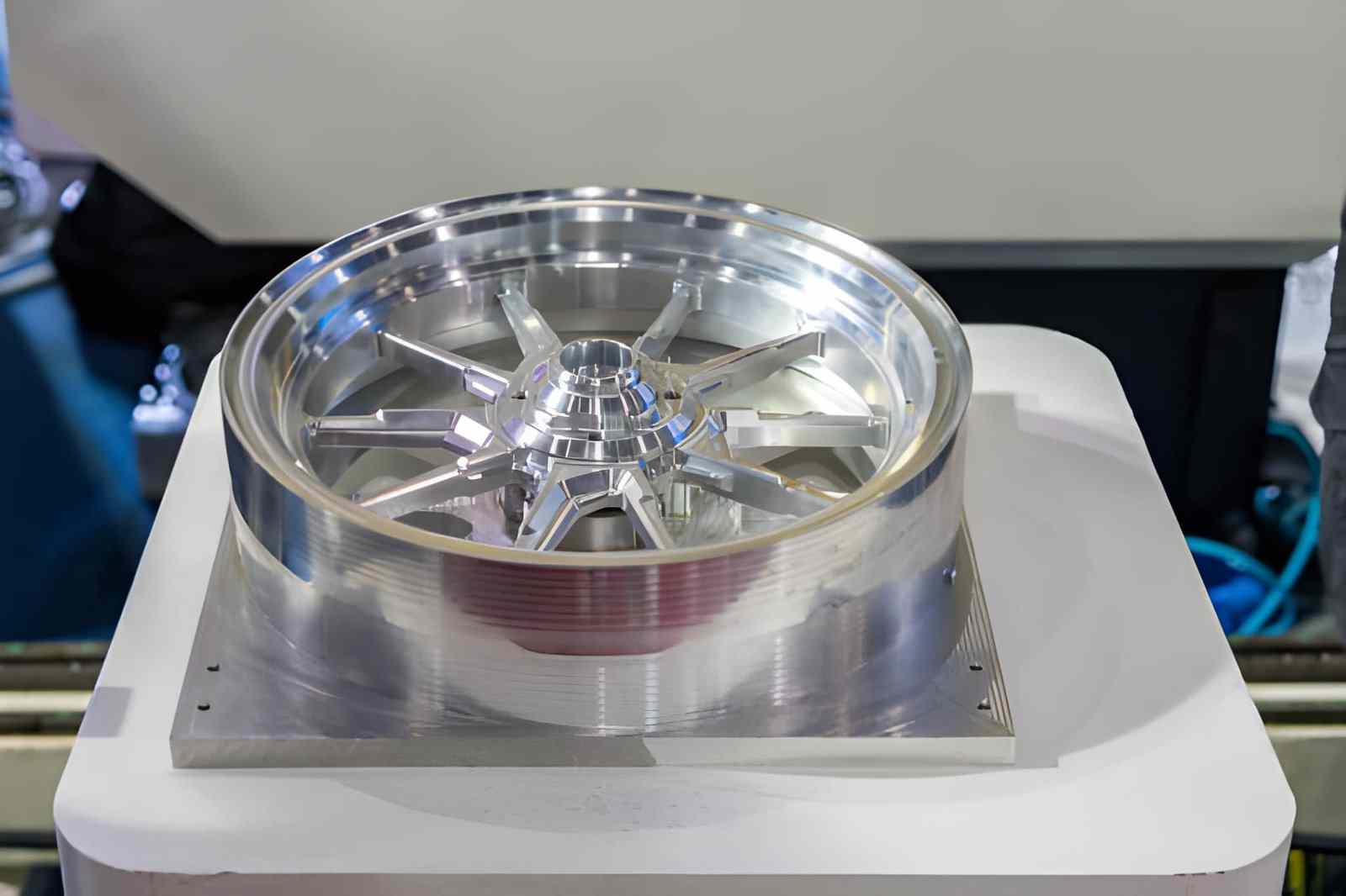
Automobile wheel manufactured by a high-precision and quality CNC machining center, made from steel material - iStock
CNC machining produces prototype parts directly from solid metal stock. The process supports features such as threaded holes, bearing seats, sealing surfaces, pockets, and machined interfaces with good dimensional control.
It is commonly used when the prototype needs actual material behavior and dimensions close to the final part.
Sheet Metal Fabrication for Structural Components and Enclosures
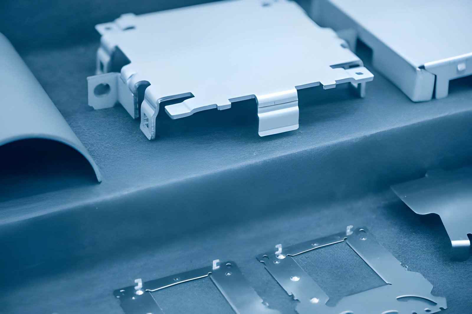
Sheet metal plate - iStock
Sheet metal fabrication produces parts through cutting and bending operations. Brackets, covers, enclosures, chassis sections, and support panels are often prototyped this way because the final part already follows folded sheet geometry.
Prototype builds help review bend locations, flange clearance, hole alignment, and assembly condition before production tooling and forming setups are finalized.
Metal 3D Printing for Complex Geometry
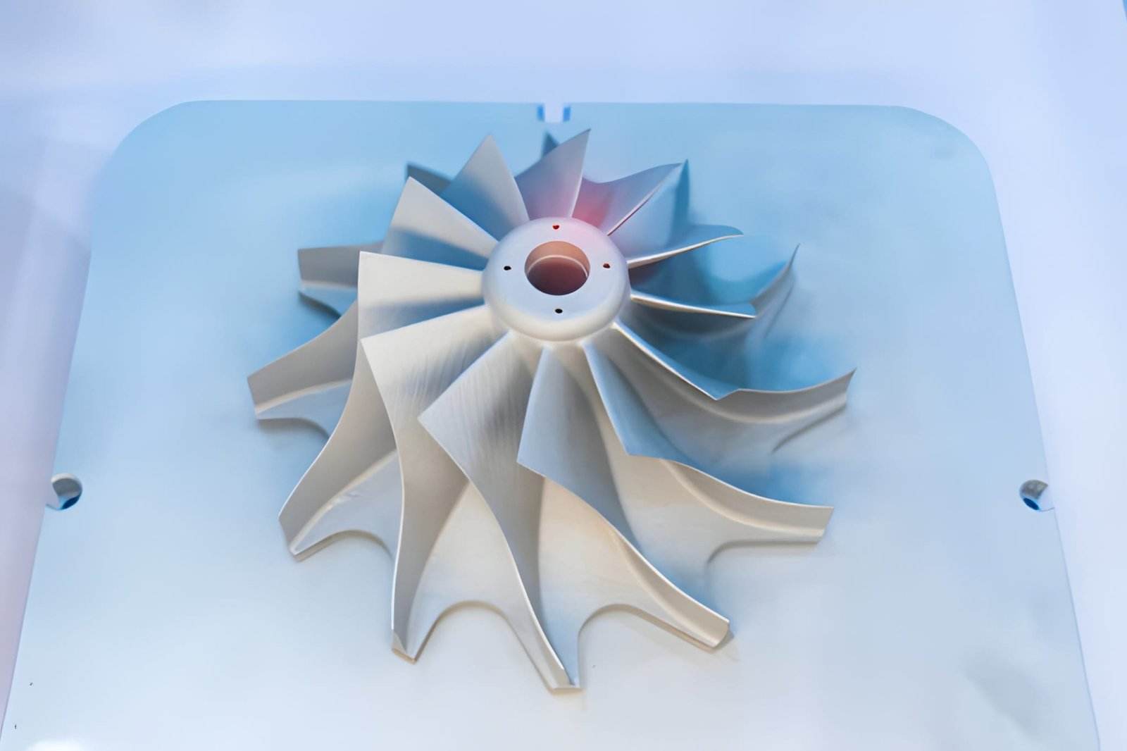
Metal products made by metal 3D printing - iStock
Metal 3D printing builds components layer by layer using metal powder. The process supports internal channels, enclosed sections, and complex geometry that standard cutting tools cannot easily access during machining.
Critical faces, threaded areas, and mating surfaces often require secondary machining after printing to improve dimensional condition and assembly fit.
Casting and Forming for Production-Oriented Prototype Evaluation
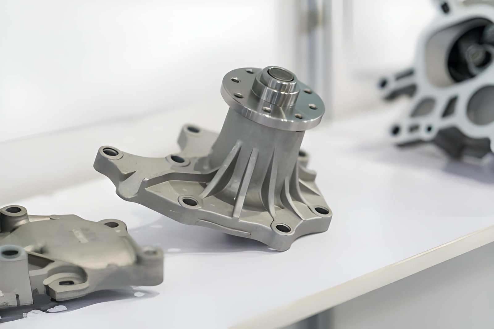
Automotive part produced by a hot forging process - iStock
Some prototypes are produced using early casting or forming methods to review how part geometry behaves before full production begins. Material flow, wall transitions, and draft conditions can be checked during this stage.
This approach helps identify geometry changes before production tooling and manufacturing plans move forward.
Table 01: Prototype Manufacturing Method Comparison
| Manufacturing Method | Best Use Case | Geometry Capability | Typical Tolerance Range | Surface Condition | Design Change Flexibility | Prototype Quantity |
|---|---|---|---|---|---|---|
| CNC machining | Functional parts, assemblies, fit validation | Medium to high complexity with accessible tool paths | ±0.02 - 0.10 mm | As-machined (typically Ra 1.6–3.2 μm) or milled smooth | High - CAD changes update directly | 1 to 100+ |
| Sheet metal fabrication | Enclosures, covers, brackets, chassis parts | Bent profiles and formed structures | ±0.1 to 0.3 mm (precision setups) | Deburred edges, uniform grain (brushed/blasted available) | High | 1 to 500+ |
| Metal 3D printing | Internal channels, consolidated parts, complex geometry | Very high | ±0.1 to 0.3 mm before finishing | Usually requires post-processing | Very high | 1 to 50 |
| Casting prototypes | Early production process evaluation | Complex shapes with draft requirements | ±0.5 to 2.0 mm | Depends on mold and process | Lower after tooling starts | 10 to 1000+ |
| Formed prototypes | Parts with repeated bends or shaped sections | Moderate geometry | ±0.2 to 1.0 mm | Process dependent | Moderate | 10 to 1000+ |
Process selection and material selection are usually evaluated together during prototyping because machining behavior, cost, and testing objectives influence each other.
Choosing Materials for Metal Prototypes
Material selection affects more than mechanical strength during prototyping. It changes machining time, part weight, testing behavior, manufacturing cost, and how closely the prototype reflects the final production component.
Lightweight Materials for Fast Iteration and Lower Cost
Aluminum 6061 is widely used during early prototype stages because it machines faster than steel and titanium alloys. Shorter machining time helps reduce cost during repeated design revisions.
Lower part weight also makes assembly checks and handling easier, especially for larger housings, covers, and structural sections. Geometry updates remain more manageable because material removal is faster during machining changes.
High-Strength Materials for Functional Testing
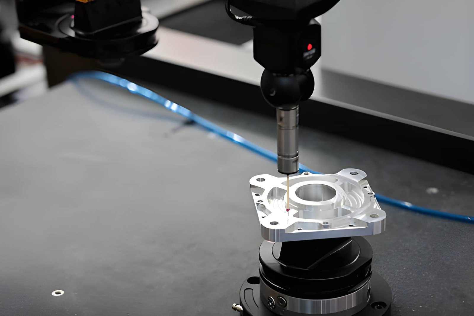
CNC milled steel part - iStock
Materials such as 4140 steel, 17-4 PH stainless steel, and titanium alloys are selected when prototypes must operate under actual loading conditions. Functional testing usually requires material behavior closer to final production performance.
Material strength also affects threaded features, contact zones, wear areas, and repeated loading sections during evaluation. Testing results become less useful if the prototype material behaves differently from the intended production alloy.
Heat, Wear, and Corrosion-Resistance Requirements
Stainless steel grades such as 304 and 316 are commonly used for prototypes exposed to moisture, chemicals, and outdoor environments. These materials help evaluate surface condition and environmental exposure during testing.
Sliding sections and high-contact areas may require harder materials or secondary surface treatment to reduce wear during repeated movement. Elevated operating temperatures also influence material selection because thermal expansion affects dimensional behavior during use.
Prototype Materials vs Production Materials
Early-stage prototypes sometimes use easier-to-machine materials to confirm assembly size, geometry, and general fit before final material selection begins. This approach helps reduce prototype cost during initial development stages.
Later functional prototypes usually move closer to production materials because strength, weight, and operating behavior become more important during testing. Material changes between prototype and production stages also affect machining strategy, tolerances, tooling behavior, and manufacturing cost.
Metal 3D Printing vs Traditional Prototype Manufacturing
Metal 3D printing and traditional manufacturing solve different prototype problems. The choice usually depends on geometry, dimensional requirements, post-processing needs, and how the prototype will be tested.
Complex Internal Features and Geometry Freedom
Metal 3D printing supports enclosed channels and complex internal geometry that are difficult to machine conventionally, although powder removal, support access, and post-processing still limit some enclosed features.
CNC machining and sheet fabrication depend on physical cutter access and process limits. Internal geometry may require multiple setups or design changes during manufacturing.
Surface Finish and Tolerance Differences
Machined parts generally provide tighter dimensional control and lower surface roughness on functional features such as sealing faces, bearing seats, and threaded interfaces. Bearing seats, threaded features, sealing faces, and mating areas often require this level of accuracy.
Printed metal parts usually need secondary machining if critical dimensions or contact surfaces are involved. Surface texture and tolerance capability vary depending on printing method and post-processing.
Mechanical Properties and Material Limitations
CNC-machined parts use standard production material stock, so the prototype material behaves similarly to the final part. Material properties remain predictable because the structure already exists before machining begins.
Printed parts can show property variation depending on print direction, support strategy, and thermal processing after printing.
Cost, Lead Time, and Production Trade-Offs
Simple machined parts usually stay more economical than printed metal parts. Complex geometry can shift the balance because machining time and setup requirements increase.
Very small quantities and highly complex geometry often favor additive manufacturing, while larger quantities usually move toward machining or production processes.
Table 02: Metal Prototype Process Comparison
| Factor | Metal 3D Printing | CNC Machining | Sheet Metal Fabrication |
|---|---|---|---|
| Internal channels | Strong capability | Limited by tool access | Not suitable |
| Geometry complexity | Very high | Medium to high | Moderate |
| Tight tolerance capability | Often requires finishing | High | Moderate |
| Surface finish from the process | Rougher before finishing | Better machined surfaces | Depends on cutting and forming |
| Material structure | Built layer by layer | Cut from solid stock | Formed from sheet material |
| Mechanical consistency | May vary by print direction | More predictable | Depends on the material and forming |
| Best for | Complex geometry and part consolidation | Functional prototypes and precision parts | Enclosures and formed structures |
| Design revision flexibility | High | High | Moderate |
| Production scalability | Lower | Medium to high | High |
Designing Metal Parts for Prototype Manufacturing
Prototype parts are often built quickly, but design decisions still affect machining effort and later production planning. A part can work during testing and still create unnecessary cost or manufacturing problems if the geometry is difficult to produce repeatedly.
Tolerance Planning for Prototype Components
Prototype drawings sometimes apply tight tolerances across the full part, even though only a few features control assembly. Critical areas such as bearing bores, shaft fits, and locating surfaces usually need closer control than cosmetic or non-contact features.
Applying ±0.02 mm on every dimension increases machining and inspection work without adding useful value to early testing.
Thin Walls, Deep Cavities, and Machining Accessibility
Very thin sections become less stable during machining because material support decreases as cutting progresses. In CNC-machined metal parts, wall thickness below roughly 1 to 1.5 mm may require additional support or lighter cutting conditions, depending on material type and feature geometry.
Deep pockets also increase cutter reach requirements. Longer tools reduce stiffness and make dimensional consistency harder to maintain across the feature.
Sheet Metal Bend and Forming Constraints
Bend geometry affects whether the part forms correctly after cutting. Bend radius is commonly kept near material thickness because extremely sharp bends can increase deformation risk.
Features such as holes, slots, and tabs placed close to bend areas can shift shape after forming and create alignment issues during assembly.
Designing Prototypes for Future Production
Prototype geometry should not ignore future manufacturing direction. A feature that machines easily in a one-piece CNC prototype may require major redesign if the production plan later moves to die casting or sheet metal forming.
Early review of draft angles, wall transitions, and tool access usually reduces redesign work between prototype and production stages.
Prototype geometry that works in CAD does not always machine efficiently at the production scale. Before moving into low-volume manufacturing, many teams review wall thickness, tool access, tolerance distribution, and feature layout to reduce later process changes and machining instability.
Bridge the Gap with Free DFM Reviews. A metal prototype that looks flawless in CAD can still drive up costs if tool access or thin-wall deflections are ignored.
To eliminate unexpected redesign loops, JLCCNC offers comprehensive Design for Manufacturing (DFM) feedback alongside our metal prototyping services. Whether you need a single CNC-machined component or a low-volume sheet metal enclosure run, our automated quoting platform ensures zero-MOQ flexibility with production-grade reality.

Precision CNC Machining Service
Professional manufacturing, fast turnaround, and quality assurance.
Prototype Validation and Manufacturing Realism
Prototype validation is not only about checking whether a part looks correct. Testing also needs to confirm that dimensions, materials, and manufacturing methods provide information that remains useful after the design moves toward production.
Functional Testing vs Visual Evaluation
A visual prototype checks overall shape, assembly space, and basic appearance. It helps review size, external form, and part interaction before investing more time in functional testing.
Functional prototypes focus on actual use conditions. Thread engagement, moving areas, load paths, and contact surfaces usually receive more attention because these areas affect performance after assembly.
When Prototype Parts Differ From Production Parts
Prototype parts do not always follow the exact production process. Early versions may remove cosmetic features, simplify geometry, or change manufacturing methods to reduce development time.
These changes help speed testing, but differences should be controlled so that important behavior does not change during evaluation.
Using Production Materials in Prototype Parts
Material selection affects testing results. A lightweight substitute material may match shape and dimensions but behave differently under load, wear, or thermal conditions.
Production materials become more important once testing moves toward strength verification, repeated use cycles, and assembly validation.
Lead Time, Cost, and Production Considerations
Prototype cost usually changes because of machining effort rather than material alone. Feature layout, quantity, and extra processing steps often decide whether a part moves quickly or creates delays.
Preparing Prototype Designs for Scalable Manufacturing
Some geometry works for one prototype part, but becomes difficult at larger quantities. Deep pockets, sharp internal corners, and difficult tool access can increase cost once production scales.
Prototype review often includes manufacturing considerations early, so design updates happen before tooling, fixtures, or production planning begins.
Geometry Complexity and Manufacturing Cost
- Deep pockets and tall walls often need longer cutters, and longer tools usually cut more slowly to keep dimensions stable.
- Parts that need machining from four or five sides require more setups than simple two-sided components.
- Small corner radii can also increase cutting time because larger tools cannot enter those areas directly.
Prototype Quantity and Manufacturing Efficiency
- A single prototype still needs programming, setup, fixturing, and inspection before machining starts.
- Producing 10 to 20 parts usually spreads setup time across multiple pieces and reduces cost per part.
- Quantity also affects process choice because some methods become practical only at larger volumes.
Finishing, Assembly, and Secondary Operations
- Machining may finish in one stage, but anodizing, heat treatment, welding, or assembly adds extra production steps afterward.
- Parts with cosmetic surfaces usually require additional hand finishing and inspection before shipment.
- Each added process creates another scheduling step during production.
Lead Time Trade-Offs Between Prototype Processes
- CNC machining often moves faster for brackets, housings, mounts, and precision metal components with accessible features.
- Metal printing may simplify difficult geometry, but support removal and finishing still add work after printing.
- Prototype tooling, casting preparation, or forming tools usually increase lead time before the first part is made.
Common Challenges in Metal Prototyping
Prototype parts often reveal manufacturing issues that are difficult to see in CAD models. Material condition, machining behavior, and feature layout can all affect how closely the finished part matches design expectations.
Dimensional Variation and Tolerance Stack-Up
Parts with many mating features can accumulate small dimensional differences across the assembly. A hole location changing by 0.05 mm may not create problems alone, but several small variations together can affect fit during assembly.
This becomes more noticeable in assemblies with pins, bearing locations, brackets, and stacked mounting features.
Warping, Distortion, and Residual Stress
Material movement sometimes appears after rough machining removes large amounts of stock. Internal stress already present inside the plate, forged material, or heat-treated stock can shift part shape during cutting.
Long plates, thin sections, and asymmetrical geometry usually need additional attention because material support changes during machining.
Surface Finish and Cosmetic Consistency
Prototype parts often include visible surfaces that also need dimensional accuracy. Tool marks, material grain variation, and finishing differences can create appearance changes between parts.
This becomes important for exposed covers, consumer products, and parts used for presentation or customer review.
Manufacturing Constraints in Complex Geometry
Very small radii, narrow channels, enclosed areas, and deep cavities can create access limits during manufacturing. CAD geometry may appear complete, but cutter size and reach still determine whether the feature can be produced efficiently.
Features with limited access often increase machining time or require geometry changes before manufacturing begins.
Where Metal Prototype Manufacturing Is Commonly Used
Metal prototype parts are used during development stages where teams need to check assembly fit, movement, function, and design decisions before production begins. Physical parts often reveal issues that are difficult to catch from CAD files alone.
Aerospace and Lightweight Structural Components
Aircraft systems use lightweight brackets, housings, support frames, and structural hardware that require weight reduction without losing strength. Prototype parts help verify mounting layouts and part interaction before final release.
Small geometry changes can affect both weight and structural behavior across larger assemblies.
EV Development and Rapid Product Iteration
Battery enclosures, motor housings, cooling plates, mounting structures, and connector components frequently change during electric vehicle development. Prototype parts help review packaging space and assembly fit as design updates continue.
Development teams often build several revisions before geometry becomes stable.
Robotics, Automation, and Precision Equipment
Robotic assemblies contain connected moving components that depend on alignment accuracy. Gear housings, actuator mounts, positioning fixtures, and sensor brackets are commonly prototyped before system integration begins.
Physical testing helps identify movement limits and assembly issues early.
Medical and Precision Devices
Medical equipment uses many small metal components with controlled dimensions and compact layouts. Prototype stages help review fit, access, and assembly behavior before production moves forward.
Dimensional control becomes more important as part size decreases.
Industrial Equipment and Machinery
Machine assemblies often include housings, shaft supports, mounting structures, and precision interfaces. Prototype parts allow teams to verify assembly sequence and physical fit before larger production runs begin.
Real assemblies often expose clearance issues that are difficult to notice during design review.
Consumer and Hardware Product Development
Product frames, metal housings, mounts, and structural parts usually pass through multiple prototype stages before production. Teams review external appearance, hand feel, assembly fit, and component interaction during development.
Physical samples help confirm design decisions before production tooling begins.
Conclusion About Metal Prototyping
Metal prototyping helps confirm design decisions before production starts. It shows the real behavior of parts under fit, load, and assembly conditions, which cannot be fully judged from CAD models.
Material choice, geometry, and manufacturing method all affect how accurate and usable the prototype becomes. CNC machining, sheet metal, and metal 3D printing each support different development needs depending on part function and complexity.
Early prototype review reduces redesign work later in production. It helps identify machining limits, assembly issues, and tolerance problems before tooling and mass production planning begin.
At JLCCNC, prototype parts are reviewed before machining to check manufacturability, material suitability, and design feasibility. Free DFM feedback is provided, with no MOQ and support from single prototypes to full production runs.
Precision CNC Machining Service
Professional manufacturing, fast turnaround, and quality assurance.
FAQ About Metal Prototyping
Q: What is metal prototyping?
Metal prototyping is the process of making sample metal parts before production starts. These parts help verify dimensions, assembly fit, movement, strength, and overall design behavior using a physical component instead of only CAD data.
Q: Which manufacturing method is best for metal prototypes?
The best method depends on what needs testing. CNC machining is commonly used for functional parts with tight dimensions, sheet metal fabrication works for enclosures and formed parts, and metal 3D printing supports geometry that is difficult to machine.
Q: Is CNC machining suitable for rapid metal prototyping?
Yes. CNC machining is one of the most common prototype methods because it produces parts directly from CAD files without production tooling. It also allows prototype parts to use production-grade materials, which improves correlation between prototype testing and final production behavior.
Q: What is the difference between metal 3D printing and CNC machining?
Metal 3D printing builds the part layer by layer from metal powder. CNC machining cuts the part from solid material stock. Printing supports enclosed channels and difficult geometry, while CNC machining usually provides better dimensional control and smoother working surfaces.
Q: Which metals are commonly used for prototype parts?
6061 aluminum is widely used because it machines quickly and keeps costs lower. Stainless steel, carbon steel, titanium, brass, and engineering alloys are also selected based on strength, corrosion resistance, wear conditions, and testing requirements.
Q: How quickly can metal prototype parts be manufactured?
Lead time changes according to geometry, material, quantity, and finishing requirements. Simple CNC parts may take 3 to 5 days, while parts needing coating, welding, heat treatment, or assembly often require additional production time.
Q: How much does metal prototyping cost?
Cost usually depends on machining time more than raw material alone. Deep cavities, tight tolerances, multiple setups, finishing steps, and low quantities often increase prototype cost.
Q: What is the fastest method for metal prototyping?
Simple precision parts are often produced faster through CNC machining. Parts with difficult internal geometry may benefit from metal printing because some features can be built directly instead of being machined through multiple setups.
Popular Articles
• Rapid Prototyping Guide: Processes Compared and How to Choose the Right Method for Manufacturing
• CNC Rapid Prototyping: Cost, Lead Time, Design Tips & Machining Service
• How is the Cost of CNC Machining Determined
• CNC machining solutions for DIY project designers
• The true cost of CNC machining services what are the main factors affecting price
Keep Learning
Rapid Prototyping Guide: Processes Compared and How to Choose the Right Method for Manufacturing
What Is Rapid Prototyping (AI generated) Various rapid prototyping parts including 3D printed, CNC machined, and sheet metal components on a workshop table. Rapid prototyping is a manufacturing approach that produces physical parts directly from CAD data within hours or days, enabling engineers to quickly validate design, fit, and function before full-scale production. Modern shops use several methods under this umbrella. 3D printing, CNC machining, and sheet processes all fall into the rapid prototyp......
What Is CNC Precision Machining? Process, Tolerances & Applications
Key Takeaways CNC precision machining focuses on controlling part variation within strict dimensional requirements rather than simply producing smaller features. Many precision machining applications can achieve tolerances around ±0.025 mm when the part design and manufacturing conditions are suitable. The final accuracy of a machined part depends on how well the process is planned, controlled, and verified from design to inspection. CNC precision machining is widely used for parts that require consis......
Additive vs Subtractive Manufacturing: Differences, Advantages, and How to Choose the Right Process
Quick Comparison: Additive vs Subtractive Manufacturing Feature Additive Manufacturing Subtractive Manufacturing How it works Builds parts layer by layer Removes material from solid stock Best for Complex geometry, prototypes, low-volume production Precision parts, tight tolerances, production runs Design freedom Excellent, including internal channels and lattices Limited by cutting tool access Typical accuracy Lower as-built accuracy; post-processing is often required High dimensional accuracy direct......
OEM vs ODM: Key Differences, Benefits, and How to Choose
Key Differences at a Glance Between OEM and ODM Factor OEM Manufacturing ODM Manufacturing Design Origin Buyer provides the product design Supplier provides an existing design Product Control Higher control over specifications and development Less control over the core product design Engineering Input Requires more engineering and product development work Requires less technical involvement Customization Extensive customization options Limited to predefined modification options Intellectual Property I......
Large Part CNC Machining: Processes, Challenges, and Manufacturing Considerations
Key Takeaways About Large Part CNC Machining Large part CNC machining handles components where size itself introduces manufacturing challenges that standard machining doesn't face, thermal effects, deflection, workholding complexity, and dimensional control over long spans. Machine travel is one constraint but not the only one, part weight, spindle access, and workholding capability define what a machine can actually do with large components as much as the stated work envelope. Accuracy on large parts......
Low Volume CNC Machining: Small Batch Production Strategies and Manufacturing Guide
Key Takeaways About Low Volume CNC Machining Low volume CNC machining is typically used for production runs ranging from a single part to roughly 1,000 units, without the tooling investment required by molding or casting processes. Small batch CNC machining is often the most practical choice when designs are still evolving, demand is uncertain, or production quantities are too low to justify dedicated tooling. CNC machining can produce production-grade parts from aluminum, stainless steel, titanium, a......