Sinker EDM: Process, Capabilities, and When to Use
22 min
- What Is Sinker EDM
- How Sinker EDM Works and Why It Differs from CNC
- Sinker EDM Electrodes: Design, Materials, and Wear
- Sinker EDM Capabilities and Limitations
- Accuracy, Surface Finish, and Process Limitations
- Sinker EDM vs Wire EDM vs CNC Machining
- Design Guidelines for Sinker EDM
- What Drives the Cost of Sinker EDM
- When to Use Sinker EDM (Applications and Decision Guide)
- Sinker EDM in CNC Manufacturing Workflows
- FAQ About Sinker EDM
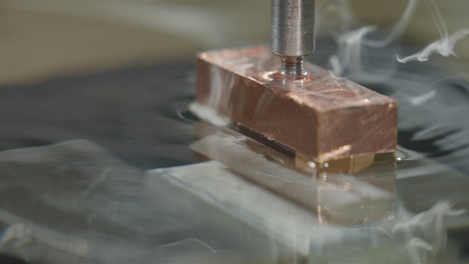
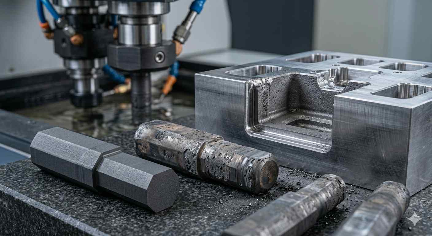
Copper electrode during sinker EDM machining
What Is Sinker EDM
Sinker EDM is a non-contact machining process that uses a shaped electrode and controlled electrical discharges to erode material from electrically conductive workpieces, typically for deep cavities and complex internal geometries. Sinker EDM is also referred to as die sinking EDM, ram EDM, or plunge EDM. It is commonly used when CNC machining cannot reach or maintain complex internal geometries.
Sinker EDM is just one of the core EDM methods. This breakdown of the three types of EDM machining explains how it compares to wire EDM and hole drilling.
How Sinker EDM Works and Why It Differs from CNC
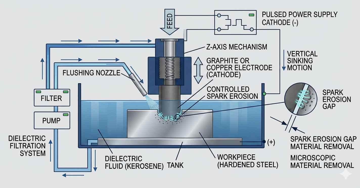
(AI generated) Diagram of Sinker EDM working
Usually, if you’re trying to get a square hole into a block of hardened tool steel, CNC milling becomes impractical. You’ll snap a tiny end mill, or the tool will deflect the second you hit a corner. This is where you material removal shifts to electrical discharge erosion.
In sinker EDM, a shaped electrode is manufactured first, and its geometry is transferred into the workpiece through controlled electrical discharges. In a sinker EDM setup, the tool is a shaped piece of graphite or copper. You aren't programming a toolpath to carve the shape; you're machining the negative of your finished part into that electrode first. When you start the cycle, the machine just feeds that shape straight into the steel. Whatever detail is on that graphite, every tiny corner or texture, gets mirrored into the workpiece. If your electrode has a scratch, your part has a scratch.
Electrical Discharge in Dielectric Fluid: The whole thing happens submerged in dielectric oil. It’s a weird process because the electrode never actually touches the metal. It just gets close enough for a spark to jump the gap. The discharge can exceed 8,000–12,000°C locally, vaporizing a tiny crater of steel. The dielectric oil then flushes the debris away. You’re basically sandblasting the part with millions of tiny lightning bolts every second.
No Mechanical Cutting Force: The best thing about a sinker is the lack of physical force. A CNC mill is always pushing against the part, which is why thin ribs or delicate walls tend to chatter or bend. Since the EDM electrode stays a few microns away from the surface, there's no mechanical stress. You can burn a slot that’s extremely narrow into a block of heat-treated D2 steel, and the part won't even know it happened.
Electrode Wear and Compensation Strategy: The catch is that the sparks don't just eat the steel, they eat the electrode, too. The corners of your graphite will start to round off as the burn progresses. Usually, you have to machine two or three electrodes for a single deep cavity: one for roughing to get the bulk of the material out, and one or two finishers to crisp up the corners and get the final dimensions right.
If you don't manage that wear, your square cavity will end up looking like a bowl. It’s a slow, messy process compared to a high-speed mill, but for hardened molds or impossible deep corners, there isn't really another way to do it.
In many production environments, sinker EDM is introduced after CNC limitations are reached. That approach is exactly why projects run late and costs spiral.
If you’re comparing EDM with traditional cutting methods, this guide on how precise CNC machining compares with other manufacturing methods explains how force, tool engagement, and material removal differ in real production.
At JLCCNC, sinker EDM isn’t an afterthought. It’s planned from the start as part of a complete machining strategy. Every part is evaluated based on geometry, material condition, and tolerance requirements before deciding whether CNC machining, wire EDM, or sinker EDM is the right fit.
This matters because sinker EDM isn’t just about the machine. It’s about electrode design, burn strategy, and process sequencing. A poorly planned job can double machining time or require unnecessary electrodes. A well-planned one runs predictably, with stable accuracy and controlled cost.
That’s the difference between “using EDM” and actually engineering for it.
Sinker EDM Electrodes: Design, Materials, and Wear
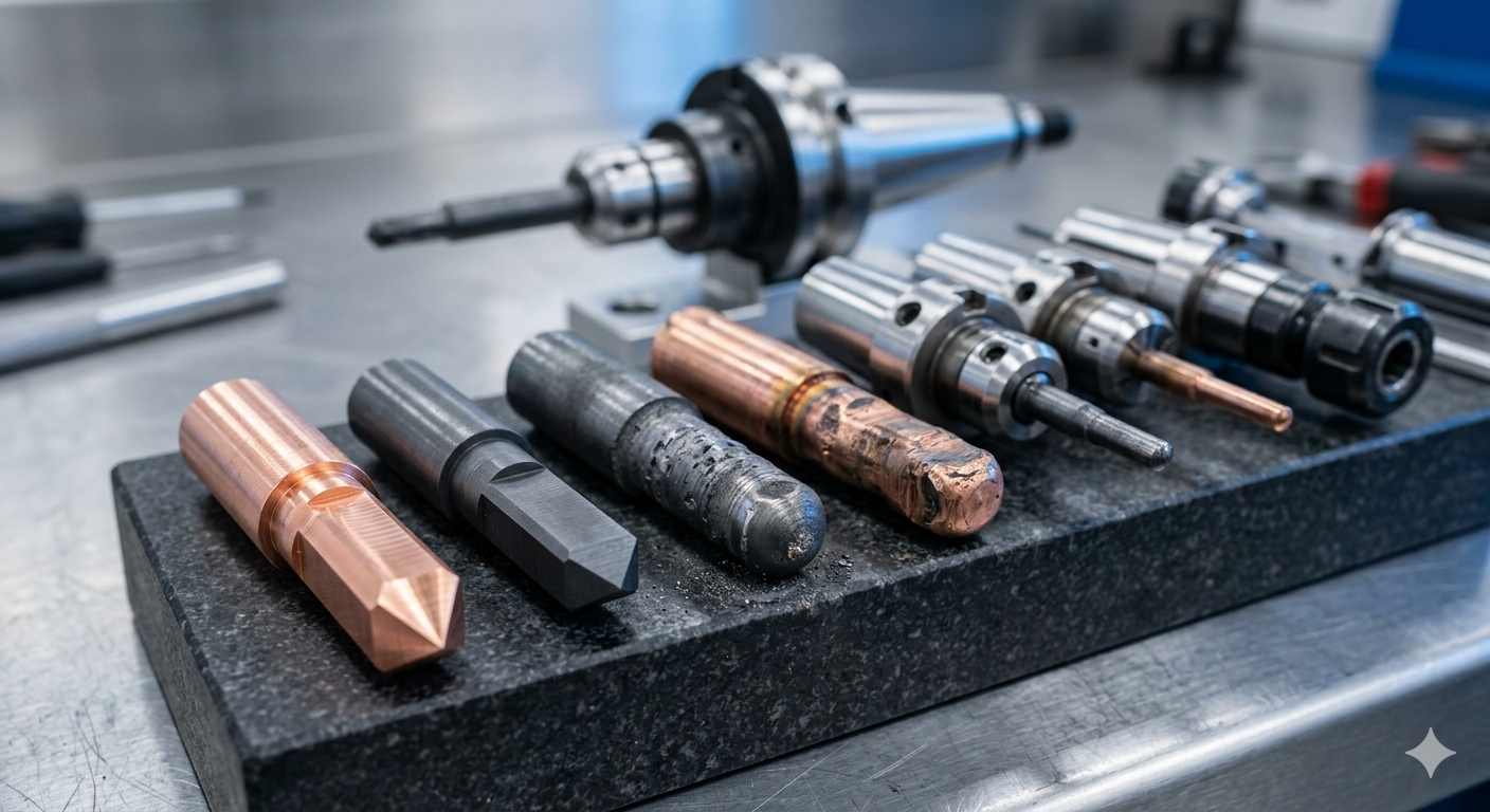
(AI generated) Close-up of graphite and copper sinker EDM electrodes
In sinker EDM, the electrode isn’t just a tool. It is the machining strategy.
With CNC, you can tweak feeds, change toolpaths, and adjust stepovers. In sinker EDM machining, most of that flexibility is gone. The electrode defines the geometry, the burn behavior, the surface finish, and even the cycle time. If the electrode is wrong, nothing downstream fixes it.
This is why experienced shops don’t “pick an electrode.” They design a sequence of electrodes that control how the material is removed from start to finish.
Common Electrode Materials (Graphite vs Copper)
Most sinker EDM electrodes come down to two materials: graphite and copper. On paper, it looks like a simple choice. In reality, it changes how the entire burn behaves.
Graphite is what most shops default to for good reason. It’s easy to machine, holds sharp edges well, and handles higher discharge energy without degrading too fast. That makes it ideal for roughing and for complex geometries where detail matters. It’s also lighter, which helps in larger electrodes where stability becomes a factor.
Copper is slower to machine but behaves differently in the spark. It produces a smoother, more stable discharge, which is why it’s often used for finishing passes where surface quality matters more than removal rate. It also wears more predictably in certain conditions, especially on fine details.
The tradeoff shows up immediately in the process. Graphite gives you speed and edge retention. Copper gives you control and finish. Most real-world jobs don’t pick one. They use both at different stages.
Electrode Design and Geometry Compensation
This is where die sinking EDM stops being straightforward.
The electrode is not a 1:1 copy of the final cavity. It has to be modified to account for spark gap, overburn, and wear. If you ignore that, your part comes out oversized, rounded, or just wrong.
The spark gap alone, typically in the range of a few microns to tens of microns, depending on the setup, means the cavity will always be slightly larger than the electrode. So you offset the geometry. Then you consider how corners erode faster than flat surfaces. Then you think about how flushing will behave in deep areas.
It stacks up quickly.
Sharp internal corners? They’ll open up during the burn. Deep ribs? They’ll see uneven erosion if flushing isn’t controlled. Fine features? They’re at risk of being lost entirely if the electrode isn’t compensated correctly.
This is why electrode design is less about CAD accuracy and more about process awareness. You’re not just modeling a shape. You’re predicting how that shape will change under thousands of spark cycles.
Electrode Wear and Replacement Strategy
Every spark removes material from both the workpiece and the electrode. That’s the part most people underestimate.
In ram EDM, wear isn’t uniform. Edges degrade faster. Corners round off. Fine features disappear first. And once that happens, the cavity starts drifting out of tolerance.
So the strategy isn’t to “use one electrode and hope it lasts.” It’s to control wear by splitting the process.
A typical approach looks like this in practice: a roughing electrode removes most of the material quickly, accepting higher wear because accuracy isn’t critical yet. Then one or more finishing electrodes step in with lower energy settings to refine the geometry and surface.
The moment you try to combine those into one electrode, you lose both speed and accuracy.
Number of Electrodes and Process Planning
This is where plunge EDM becomes a planning exercise, not just a machining operation.
Simple cavities might get away with one or two electrodes. Complex molds? You’re easily looking at a full electrode set, roughing, semi-finishing, finishing, sometimes even detail electrodes for critical features.
Each one adds cost upfront. But skipping them usually costs more later in scrap, rework, or missed tolerances.
The real decision isn’t “how many electrodes do we want?” It’s “how much risk can we afford in the burn?”
More electrodes mean:
- better dimensional control
- more consistent surface finish
- lower risk of losing fine features
Fewer electrodes mean:
- faster setup
- lower upfront cost
- higher chance of variation
Good sinker EDM process planning finds the balance. Not overengineering the job, but not gambling on a single electrode either.
At this level, electrode strategy is what separates a clean, repeatable cavity from one that looks right on CAD but fails on the machine.
This is usually the point where designs start looking fine on screen but questionable in production.
Deep cavities, sharp corners, or hardened materials can quietly push a part into sinker EDM territory, even if it wasn’t planned that way. And once electrodes and burn time enter the equation, cost and lead time change fast.
If you’re unsure whether a feature should be machined with CNC or sinker EDM, upload your file to JLCCNC. You’ll get instant pricing along with a manufacturability review that flags where EDM is required, how many electrodes are needed, and how it impacts production time.
It’s a quick way to catch expensive decisions before they reach the shop floor.
Sinker EDM Capabilities and Limitations
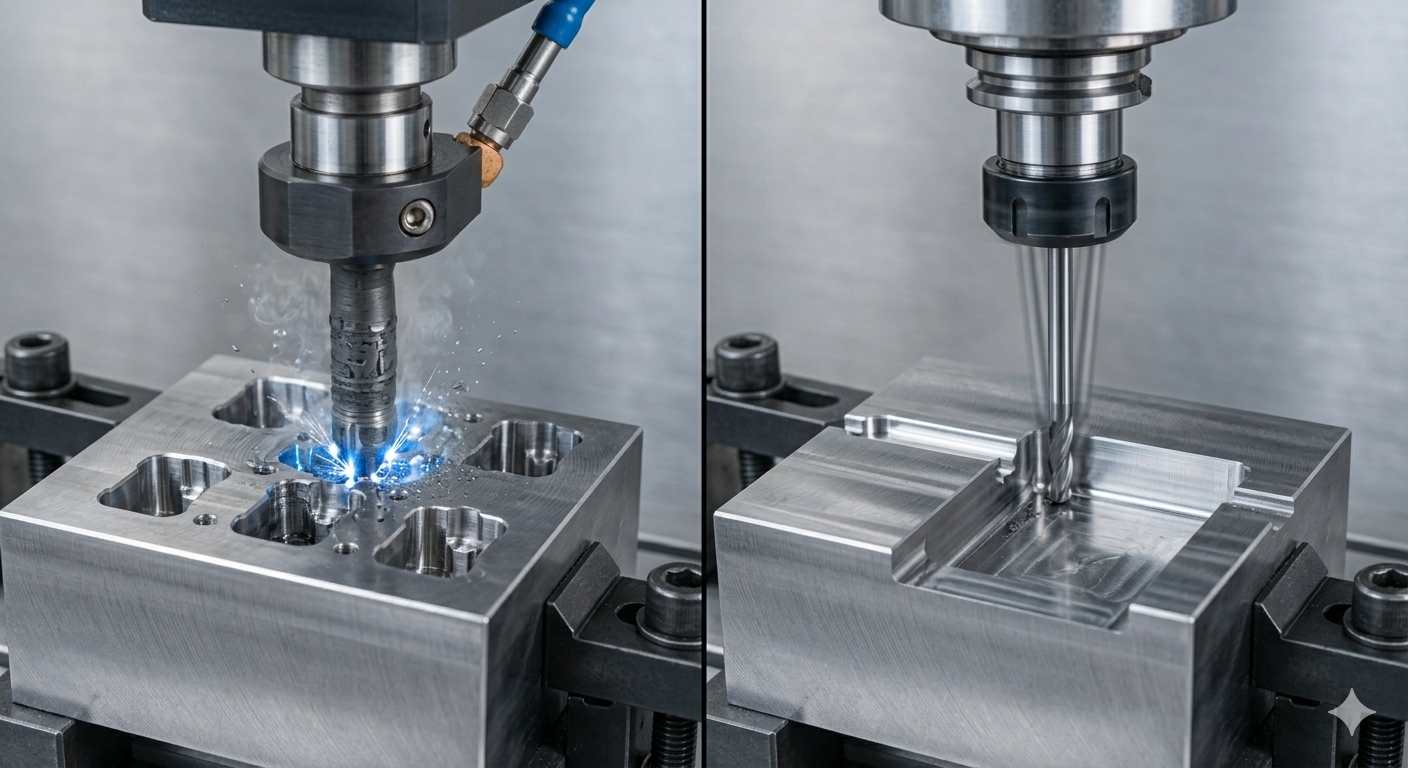
(AI generated) Comparison of sinker EDM cavity machining and CNC tool limitation
Sinker EDM is applied selectively, not as a general-purpose machining method. It is typically introduced when part geometry, material condition, or structural sensitivity makes conventional cutting unreliable. In practice, its performance is defined by accessibility, electrode strategy, and process stability rather than cutting efficiency.
Geometries It Handles Well (Deep Cavities, Sharp Corners)
This is where sinker EDM machining earns its place.
Sinker EDM is suited for closed cavities, deep internal geometries, and features that are difficult to maintain with rotating tools. Typical use cases include mold cavities, sharp internal corners beyond tool radius limits, and thin ribs where conventional machining introduces instability.
Feature complexity is primarily constrained by electrode manufacturability and access. As long as the electrode can be produced and positioned correctly, geometric fidelity can be maintained across depth and detail.
Material Conditions (Hardened Steels, Difficult Alloys)
Sinker EDM process is used on electrically conductive materials, typically after heat treatment. Hardened tool steels, wear-resistant alloys, and materials that cause excessive tool wear in CNC machining are common applications.
This allows final geometry to be produced without reintroducing distortion from post-machining heat treatment, which is often a limiting factor in conventional workflows.
Limitations (Speed, Accessibility, Electrode Dependency)
Material removal rate is significantly lower compared to CNC machining, particularly for large volumes. For this reason, sinker EDM is not used for bulk material removal and is typically applied after rough machining.
Accessibility is a primary constraint. Features must be reachable by the electrode, usually along a controlled axis. Deep blind cavities require effective flushing to maintain stable discharge conditions; otherwise, debris accumulation can affect dimensional control and surface quality.
Electrode dependency introduces additional process overhead. Each cavity requires at least one electrode, and complex geometries often require multiple electrodes for roughing and finishing stages. This increases setup time, tooling cost, and process planning complexity.
In practical applications, sinker EDM is most effective when used for specific features where geometry, material condition, or stability requirements limit the reliability of conventional machining. Sinker EDM is best viewed as a precision finishing process rather than a bulk material removal method.
Accuracy, Surface Finish, and Process Limitations

(AI generated) EDM machined surface texture being inspected
Achievable Tolerances and Dimensional Control
Sinker EDM can hold tight tolerances, typically in the range of ±0.005 mm to ±0.01 mm in stable conditions. Since there’s no cutting force, you don’t deal with tool deflection, which helps maintain geometry in deep cavities and thin features. Accuracy comes from controlling spark gap, electrode geometry, and burn parameters rather than mechanical precision alone.
Surface Finish Characteristics (EDM Texture)
Surface finish is defined by the spark itself. Each discharge leaves a microscopic crater, creating the characteristic matte EDM texture. Roughing passes leave a visibly coarse surface, while finishing passes with lower energy can achieve fine finishes down to Ra ~0.2–0.8 µm. You’re not “polishing” the surface during machining, you’re refining crater size.
Error Sources (Electrode Wear, Overburn, Discharge Stability)
Most variation in sinker EDM machining traces back to three things: electrode wear, overburn (spark gap enlargement), and unstable discharge conditions. As the electrode erodes, geometry shifts. If spark energy isn’t controlled, the cavities oversize slightly. And if flushing or dielectric conditions fluctuate, the burn becomes inconsistent, affecting both size and finish.
Practical Limits (Speed, Cost, Feature Accessibility)
The limits are straightforward. It’s slower than CNC for bulk removal, electrode design adds upfront cost, and deep blind features depend heavily on flushing to stay stable. Accessibility is also tied to electrode geometry. If you can’t design or position the electrode, you can’t machine the feature.
Sinker EDM vs Wire EDM vs CNC Machining
| Factor | Sinker EDM (Die Sinking EDM) | Wire EDM | CNC Machining |
|---|---|---|---|
| Geometry Type | Closed cavities, blind features, 3D forms | Through-cuts, profiles, open geometries | External surfaces, pockets, and general 3D shapes |
| Material Removal | Spark erosion using a shaped electrode | Spark erosion using a moving wire | Mechanical cutting (tool + chip removal) |
| Force on Part | No cutting force | No cutting force | High cutting forces present |
| Accuracy | High (±0.005–0.01 mm typical) under controlled conditions | Very high (up to ±0.002–0.005 mm) depending on setup | High, but affected by tool deflection |
| Surface Finish | Matte EDM texture, finish depends on burn passes | Fine finish, smoother than sinker EDM | Depends on tooling and finishing strategy |
| Speed | Slow (especially for large volumes) | Moderate (faster than sinker for cuts) | Fast for bulk removal |
| Cost Structure | Electrode design + burn time | Machine time + wire consumption | Tooling + machine time |
| Typical Use Cases | Molds, dies, deep cavities, intricate internal features | Precision cutting of plates, dies, profiles | General machining, roughing + finishing |
If your design involves through-cuts rather than blind cavities, this guide on EDM wire cutting explains why it’s often the more efficient alternative.
When Sinker EDM Is the Better Choice
Die sinking EDM becomes the right choice when the geometry can’t be reached or held by cutting tools. Deep cavities, sharp internal details, and hardened materials are the typical triggers.
It’s also the better option when part stability matters more than speed. If cutting forces would distort the feature or compromise accuracy, EDM removes that variable completely.
In practice, it’s rarely used alone. CNC handles the bulk material removal, and sinker EDM process steps in where precision, geometry, or material condition makes conventional machining unreliable.
Design Guidelines for Sinker EDM
Sinker EDM doesn’t give you the same freedom as CNC machining. You’re not just designing a part, you’re designing something that can be replicated through an electrode. That single constraint changes everything about how features should be approached.
Designing for Electrode Access and Clearance
Every cavity you design has to be reachable by an electrode. Sounds obvious, but this is where a lot of designs quietly fail.
Unlike a cutting tool that can approach from multiple angles, a sinker EDM electrode typically moves in a controlled vertical path. If your geometry blocks that path, the feature becomes either impossible or requires multiple electrodes and setups.
Deep internal features with overhangs or hidden corners usually force redesign. Even small access restrictions can multiply costs because they require custom electrode shapes or secondary operations.
In practice, if you can’t clearly visualize how the electrode enters and exits the cavity, the design isn’t ready.
Managing Depth-to-Width Ratio in Cavities
This is one of the most underestimated constraints.
As cavities get deeper relative to their width, flushing becomes harder. Debris builds up, sparks become unstable, and accuracy starts drifting. The process slows down dramatically.
Shallow, open cavities machine predictably. Deep, narrow ones turn into time sinks.
Once you push into high depth-to-width ratios, you’re no longer just machining. You’re managing instability. That usually means slower parameters, more electrode wear, and sometimes multiple roughing and finishing passes just to maintain control.
Allowing for Electrode Wear Compensation
Electrodes don’t stay perfect. Every spark erodes both the workpiece and the electrode itself.
If your design assumes a perfect, unchanging tool, you’ll see dimensional drift across the cavity, especially in sharp corners and fine details.
This is why electrode compensation is built into the process. Slight offsets are applied to account for expected wear, and in high-precision work, separate electrodes are used for roughing and finishing.
From a design perspective, extremely tight internal features or sharp corners increase sensitivity to wear. You’re essentially asking the process to hold precision while the tool itself is slowly changing shape.
Balancing Surface Finish vs Machining Time
EDM can produce very fine surface finishes, but not for free.
A roughing pass removes material quickly but leaves a textured surface. To refine that, multiple finishing passes are required with lower energy sparks. Each pass improves the finish but adds significant time.
So when a design demands a mirror-like cavity finish across large areas, machining time increases sharply.
This is where good design decisions save real money. Not every surface needs a fine EDM finish. Functional surfaces might justify it, but non-critical areas usually don’t.
What Drives the Cost of Sinker EDM
(AI generated) Worn and new EDM electrodes next to machined steel cavity
Most people assume EDM is expensive because it’s “advanced.” That’s not really it. Cost comes from time, electrodes, and complexity, stacking on top of each other.
Electrode Design and Manufacturing Cost
Every cavity starts with an electrode. And that electrode has to be machined first.
Simple geometries need simple electrodes. Complex cavities, sharp features, or fine details often require multiple electrodes, each one designed, machined, and validated separately.
In many jobs, electrode production alone accounts for a large portion of the total cost before EDM even begins.
Machining Time from Low Material Removal Rate
EDM is not fast. It removes material through controlled spark erosion, not aggressive cutting.
Compared to CNC machining, the material removal rate is significantly lower. That’s the tradeoff for being able to machine hardened materials and complex internal geometries.
The deeper or more intricate the cavity, the longer the machine runs. And in EDM, machine time directly translates to cost.
Multiple Electrodes for Complex Cavities
One electrode rarely does everything.
A typical process might involve:
- a roughing electrode to remove bulk material
- one or more semi-finishing electrodes
- a final finishing electrode for accuracy and surface quality
Each stage improves precision, but also adds setup time and tooling cost.
Complex parts can easily require several electrodes just to achieve the final geometry.
Finishing Requirements and Secondary Processes
Surface finish expectations have a huge impact on cost.
If the part requires fine surface quality directly from EDM, additional low-energy passes are needed. These passes are slow and increase cycle time significantly.
In some cases, parts also go through secondary processes like polishing or surface treatment, especially for molds or high-precision cavities.
So the real cost isn’t just machining. It’s the combination of electrode prep, EDM passes, and finishing requirements.
When to Use Sinker EDM (Applications and Decision Guide)
Most teams don’t choose sinker EDM upfront. They end up there after CNC hits a wall. The better approach is knowing early where it actually makes sense.
Decision Guide: When Sinker EDM Makes Sense
| Scenario | Sinker EDM Fit | Why It Works | Better Alternative (If Any) |
|---|---|---|---|
| Deep, blind cavities | Highly suitable | No tool deflection, stable depth accuracy | CNC struggles with tool reach |
| Sharp internal corners | Highly suitable | No tool radius limitation from cutters | CNC requires corner radii |
| Hardened steels (post-heat treat) | Highly suitable | No cutting force, largely independent of material hardness | Grinding (limited geometry) |
| Complex mold cavities | Highly suitable | Replicates detailed electrode geometry | CNC for roughing only |
| Thin ribs or fragile features | Suitable with limitations | No mechanical stress on the part | CNC risks deflection or breakage |
| Large open features | Suitable with limitations | Too slow for bulk removal | CNC milling is far more efficient |
| Through cuts/profiles | Not recommended | Not designed for cutting through | Wire EDM is better |
| Simple geometries | Not recommended | Overkill process | CNC machining is faster and cheaper |
Typical Industrial Applications (Molds, Dies, Precision Cavities)
This is where sinker EDM actually earns its place.
Injection molds, die casting tools, forging dies, anything with deep cavities and fine internal detail. These parts aren’t just complex; they’re usually hardened, which makes traditional cutting inefficient or impossible.
You’ll also see it in aerospace and medical tooling, where precision cavities and sharp internal features are required without inducing stress into the material.
When It Solves Problems CNC Cannot
Sinker EDM steps in when cutting tools hit physical limits.
If a feature is too deep, too sharp, or inside a hardened material, CNC either becomes unstable or outright impossible. Tool deflection increases, chatter shows up, and accuracy drops.
EDM removes all of that because there’s no cutting force. The electrode doesn’t push. It erodes. That single difference is why it handles geometry that CNC simply can’t maintain.
When Another Process Is More Efficient
EDM is not a default choice. It’s a solution to specific constraints.
If the part is soft, open, and accessible, CNC will always be faster and cheaper. If the feature goes through the part, wire EDM is usually the better option.
And if you’re removing a lot of material, EDM becomes painfully slow.
So the real rule is simple:
Use CNC for speed and volume.
Use wire EDM for through-cuts.
Use sinker EDM when geometry or material blocks everything else.
Sinker EDM in CNC Manufacturing Workflows
In real production, sinker EDM almost never runs alone. It’s part of a sequence. CNC does what it’s good at: bulk removal and setup geometry. EDM finishes what CNC can’t.
Combining EDM with CNC Machining
The most efficient workflow is hybrid.
CNC handles the rough shape first. It removes most of the material quickly and defines reference features. Then EDM comes in to finish critical areas, sharp corners, deep cavities, and hardened zones.
Trying to do everything with EDM wastes time. Trying to force everything through the CNC risks failure. The balance is where good manufacturing happens.
Process Sequencing (Roughing vs EDM Finishing)
The order matters more than people think.
You rough with CNC while the material is still easier to machine. If heat treatment is required, it happens before EDM. Then sinker EDM is used to bring the part to the final geometry.
This sequence avoids excessive electrode wear and keeps EDM focused on precision, not bulk removal.
A typical flow looks like this:
CNC roughing → heat treatment (if needed) → EDM finishing → optional polishing
Engineering Considerations Before Quoting
Most cost surprises in EDM come from decisions made before machining even starts.
Electrode count, cavity depth, required finish, and tolerance all stack together. A design that looks simple on a screen can require multiple electrodes and long burn times in reality.
That’s why early review matters.
At JLCCNC, parts aren’t just quoted. They’re evaluated for process fit. If a feature is better suited for CNC or wire EDM, it’s flagged early. If EDM is required, the electrode strategy and machining sequence are planned before production starts.
That’s what prevents slow cycles, unnecessary electrodes, and expensive rework later.
If you’re working on a part with deep cavities or tight internal features, upload your CAD file for a manufacturability check before committing to production. JLCCNC reviews the part for process fit and then provides a fast quote starting from $1, with lead times as short as 3 days for suitable parts. It is a more efficient way to catch EDM risks early than to deal with delays or rework later.
FAQ About Sinker EDM
Q: What is sinker EDM?
A machining process that uses shaped electrodes and electrical sparks to erode material and form cavities.
Q: How does sinker EDM work?
It removes material through controlled spark erosion in a dielectric fluid without physical cutting contact.
Q: What is the difference between sinker EDM and wire EDM?
Sinker EDM creates blind cavities using an electrode, while wire EDM cuts through material using a moving wire.
Q: Is sinker EDM more accurate than CNC machining?
It can be more precise for complex internal features, especially in hardened materials, but not universally more accurate.
Q: Why is sinker EDM expensive?
Cost comes from electrode manufacturing, slow material removal rates, and multiple finishing passes.
Q: What is the difference between ram EDM and sinker EDM?
They’re the same process. “Ram EDM” and “sinker EDM” are just different names for die-sinking EDM.
Q: Can sinker EDM machine hardened steel?
Yes. Sinker EDM is commonly used after heat treatment because material hardness does not significantly affect the process, as long as the material is electrically conductive.
Q: Why does sinker EDM require multiple electrodes?
Because electrodes wear during machining, especially at edges and corners. Multiple electrodes (roughing and finishing) are used to maintain dimensional accuracy and surface quality.
Q: What surface finish can sinker EDM achieve?
Surface finish depends on discharge energy. Roughing passes produce a coarse texture, while finishing passes can reach approximately Ra 0.2–0.8 µm under controlled conditions.
Popular Articles
• Cutting with Precision: A Comprehensive Guide to CNC Water Jet Technology
• CNC Coolant Explained: Types, Maintenance & Safety
• Rake Angle in Machining: Machinists’ Guide to Perfect Cuts
• What Steps Are Taken To Minimize Waste In CNC Machining Processes?
• How EDM Wire Cutting Works: Complete Guide to Precision CNC Wire Cutting
Keep Learning
Chatter in Machining: Causes, Effects, and How to Reduce It
CNC milling operation producing visible chatter marks on an aluminum workpiece Quick Chatter Diagnosis Checklist Symptom Most Likely Cause First Action High-pitched squeal Regenerative chatter Change spindle speed ±15% Chatter only in deep pockets Excessive tool overhang Shorten tool Chatter on thin walls Low workpiece rigidity Improve fixturing Chatter after tool replacement Runout / holder issue Check tool holder Chatter only during finishing DOC too small / rubbing Increase feed or adjust speed It ......
What Is Tool Offset in CNC? Types, Setup & Best Practices
CNC tool offset setup with measurement overlay Key Takeaways CNC offsets connect programmed intent with actual cutter position. Length data guides Z-axis depth control. Radius data protects part size during contour milling. Geometry values define the cutter's measured baseline. Wear values support fine correction during production. Verified data lowers scrap risk before full machining. Good offset habits protect tools, fixtures, and parts. In the context of CNC machining , tool offset is the quiet set......
Trochoidal Milling: Complete Guide to High-Efficiency CNC Machining
Key Takeaways Trochoidal milling combines circular cutter motion with continuous forward feed. The cutter normally engages 5 to 20% of its diameter instead of making a full-width cut. A smaller engagement angle limits force changes during slotting and pocket roughing. Low radial engagement often allows greater axial depths of cut than conventional slot milling. CAM software calculates the circular path automatically from the selected machining parameters. This strategy is widely applied to titanium, s......
What Is Die Casting? Process, Materials, and Applications
Key Takeaways Die casting is a metal casting process that forces molten metal into a reusable steel mold under high pressure, producing parts with tight tolerances and good surface finish at high volume. Aluminum die casting is the most common form by far, thanks to its combination of light weight, decent strength, and good corrosion resistance. The die casting process runs through mold preparation, injection, cooling, and ejection in a cycle that can repeat every few seconds to minutes depending on p......
First Angle vs Third Angle: Understanding Orthographic Projection Methods
Key Takeaways Orthographic projection is the system that lets a 3D part be represented through multiple 2D views, front, top, side, and so on. First angle projection and third angle projection are the two standard methods for arranging those views, and they place views in opposite positions relative to the object. First angle projection is the ISO standard used across most of Europe, India, China, Russia, and many other countries following ISO standards Third angle projection is the standard in the Un......
Micro EDM Machining: Capabilities, Materials, and Applications for Precision Components
Key Takeaways About Micro EDM Machining Only electrically conductive materials can be machined. Hole diameters can reach below 50 μm on specialized equipment. The process produces almost no mechanical cutting force, making it suitable for thin or delicate features. Surface integrity still requires attention because recast layers and heat-affected zones may remain after machining. Micro EDM is often combined with CNC machining, with milling producing the main geometry before EDM finishes critical micro......