Sheet Metal Cutting: Processes, Methods, Tools, and Accuracy
18 min
- What is Sheet Metal Cutting?
- Sheet Metal Cutting Process (From Design to Inspection)
- Major Types of Sheet Metal Cutting Methods
- Sheet Metal Cutting Tools and Equipment
- What are the Main Parameters in the Sheet Metal Cutting Process?
- Sheet Metal Cutting Accuracy and Tolerances
- When Sheet Metal Cutting Is Not the Best Choice
- Key Takeaways
- FAQs
What is Sheet Metal Cutting?
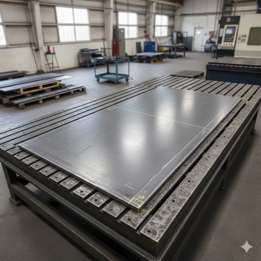
(AI generated) Sheet metal cutting setup showing flat steel sheet positioned for industrial fabrication
Sheet metal cutting is the process of separating flat metal sheets into specific shapes using mechanical, thermal, or abrasive methods. It sounds straightforward, but in manufacturing, it’s rarely just “cutting.” The way the material is separated influences fit, weld behavior, bending performance, and overall part quality.
In practice, the sheet metal cutting process can look very different depending on the shop. Some rely on mechanical shear systems. Others use high-energy systems like lasers or plasma. The choice affects speed, cost, edge condition, and sheet metal cutting accuracy and tolerances.
Engineers don’t usually think about cutting as an isolated step. They think about what happens after, forming, fastening, coating, and assembly. If the cut edge is inconsistent or distorted, problems show up later.
The cut quality directly affects downstream forming, especially in sheet metal bending operations where edge condition influences crack resistance and dimensional stability.
At JLCCNC, sheet metal cutting is not treated as a basic separation step. It is treated as a controlled manufacturing operation that sets the foundation for everything that follows.
We work with engineers, product developers, and manufacturing teams who understand that dimensional stability, edge integrity, and repeatability matter.
From thin aluminum enclosures to structural steel components, we apply the appropriate sheet metal cutting methods based on function, not assumption. Laser systems for precision profiles. Plasma for heavy-duty steel. Carefully selected sheet metal cutting tools matched to volume and tolerance expectations.
Because in production environments, the quality of the cut determines the quality of the build.
Applications and Industries
Most fabricated metal components begin with flat stock, which makes sheet metal cutting foundational across industries.
Automotive suppliers cut body panels and brackets in high volumes. Aerospace manufacturers focus heavily on sheet metal cutting accuracy and tolerances because alignment and weight control are critical. Industrial equipment producers use various types of sheet metal cutting for enclosures, frames, and mounting structures.
Even HVAC systems, electrical cabinets, and architectural panels depend on a reliable sheet metal cutting process to maintain dimensional consistency.
Sheet Metal Cutting Process (From Design to Inspection)
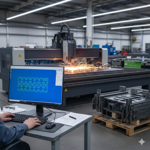
(AI generated) Sheet metal cutting process from digital nesting to finished inspected parts in a factory
The sheet metal cutting process doesn’t start at the machine. It starts at the drawing. Geometry, tolerances, material selection, and downstream forming all influence how the cut should be made.
Industrial users usually care about three things: repeatability, cost control, and dimensional stability. Getting those right requires more than just choosing between different types of sheet metal cutting. It requires thinking through preparation, execution, and inspection as one connected workflow.
Material Preparation and Nesting
Before any sheet metal cutting tools are powered on, the material has to be selected, inspected, and staged properly. Thickness variation, surface condition, and flatness all affect final cutting accuracy and tolerances.
Sheets are typically loaded into a CNC system where nesting software arranges part profiles to minimize scrap. Good nesting reduces waste, shortens cycle time, and keeps heat distribution more uniform during thermal sheet metal cutting methods like laser or plasma.
Grain direction may also be considered, especially if parts will be bent later. Poor orientation at this stage can create forming cracks or inconsistent structural behavior. For industrial production, that kind of oversight multiplies quickly.
Material prep sounds simple, but it quietly determines whether the rest of the sheet metal cutting process runs smoothly.
Cutting Execution
Once the program is finalized, cutting begins according to the selected method. The actual sheet metal cutting process varies depending on whether the operation is mechanical, thermal, or abrasive.
With mechanical systems, force is applied through dies or blades to shear the material. Thermal systems, such as laser or plasma, concentrate energy to melt and remove material along the programmed path. Waterjet systems erode the material using high-pressure abrasive flow.
Operator oversight still matters, even in automated environments. Focus height, feed rate, gas pressure, and tool condition all influence edge integrity. Small parameter shifts can affect cutting accuracy and tolerances, especially on tighter industrial parts.
In high-volume settings, consistency is the priority. In prototype work, flexibility matters more. Either way, the execution phase determines whether the cut matches the design intent or introduces rework downstream.
Edge Quality, Burr Removal, and Inspection
After separation, the part is not automatically finished. Edge condition depends heavily on the chosen sheet metal cutting methods.
In a real-world shop, the cut is rarely the final word. Whether it's mechanical burrs that need a trip through the tumbler or the heat-affected zone and dross left behind by a laser, you have to account for secondary finishing. It’s not a failure of the tool; it’s just the reality of meeting safety and surface specs before a part moves down the line.
That’s where inspection steps in. It’s more than just a quick glance. It’s about verifying dimensions against the print and checking for flatness to make sure the part won't fight the assembly jig. On high-precision jobs, we move past the calipers and pull in CMMs or optical scanners to catch tolerance drift before it turns an entire batch into scrap. The goal is simple: find the deviation now, so the guys in assembly aren't trying to force parts that don't fit later.
If your design depends on clean edges, stable dimensions, and consistent repeatability, the sheet metal cutting process cannot be left to guesswork.
Major Types of Sheet Metal Cutting Methods
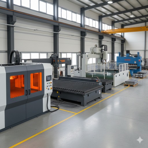
(AI generated) Different sheet metal cutting methods used in an industrial manufacturing facility
All sheet metal cutting methods remove material, but they do it in fundamentally different ways. That difference isn’t just technical, it affects stress in the part, downstream forming behavior, weld quality, coating adhesion, and long-term dimensional stability.
If you look closely at the types of sheet metal cutting used in production, they fall into four categories based on how material separation actually happens: melting, ionized erosion, abrasive erosion, or mechanical fracture.
Understanding that difference matters more than the marketing labels.
1. Laser Cutting (Precision, Speed, Thin–Medium Thickness)
Laser systems remove material by concentrating energy into a focused beam that melts and expels metal along a programmed path. Assist gas, oxygen or nitrogen, clears molten material and influences edge chemistry.
In modern fabrication environments, laser is often the default sheet metal cutting process for thin to medium thickness materials. It offers strong sheet metal cutting accuracy and tolerances, especially for intricate geometries, tight internal corners, and small hole features.
However, it is important to consider that:
Laser cutting introduces localized thermal stress, which may require sequencing and heat management strategies to control distortion in thin or elongated parts. Experienced programmers compensate by distributing heat load across the sheet.
Laser also shines in repeatability. Once dialed in, sheet metal cutting tools in laser systems produce extremely consistent parts across large batches, making them ideal for enclosures, brackets, and precision panels where assembly alignment matters.
Typical use cases:
- Electrical enclosures
- Architectural panels
- Automotive brackets
- Precision mounting plates
2. Plasma Cutting (Speed, Thick Steel, Lower Precision)
Plasma cutting uses a high-velocity jet of ionized gas to melt and blow away material. It’s aggressive, fast, and well-suited for thicker carbon steel.
Among the types of sheet metal cutting, plasma is often chosen when speed and thickness capacity outweigh tight tolerances. It handles heavy plate far more economically than laser at certain thickness ranges.
However, repeatable tolerance control is typically looser compared to laser. Edge angularity and heat-affected zones are more pronounced. For structural components, that’s usually acceptable. For tight-fitting assemblies, secondary machining may be required.
One advantage plasma offers in industrial settings is robustness. It tolerates mill scale and surface contaminants better than laser systems. In fabrication shops processing structural frames or heavy equipment parts, reliability matters.
Typical use cases:
- Structural base plates
- Equipment frames
- Heavy-duty brackets
- Agricultural and construction machinery parts
If you're deciding between thermal sheet metal cutting methods, our detailed comparison of laser cutting vs plasma cutting breaks down cost, thickness limits, and achievable tolerances.
3. Waterjet Cutting (Cold Cutting, Mixed Materials)
Waterjet systems remove material through high-pressure abrasive erosion. There is no heat input. That alone changes how the sheet metal cutting process behaves compared to thermal methods.
Because it’s a cold cutting method, there is no heat-affected zone, no microstructural change, and virtually no thermal distortion. That makes waterjet valuable for materials sensitive to heat, hardened steels, aluminum alloys, or layered materials.
Cutting accuracy and tolerances can be very strong when calibrated properly, though taper must be controlled through dynamic head adjustment.
Waterjet also expands its capability beyond metal. It can cut composites, rubber, plastics, and stacked materials in a single setup. That flexibility makes it useful in aerospace, energy, and specialized manufacturing environments.
Typical use cases:
- Aerospace structural components
- Mixed-material assemblies
- Decorative architectural panels
- Heat-sensitive alloys
We’ve covered the full waterjet cutting process in more depth, including how taper compensation and abrasive flow rate affect precision.
4. Mechanical Cutting (Shearing, Punching, Blanking)
Mechanical sheet metal cutting tools physically fracture material through force. Shearing uses opposing blades. Punching and blanking rely on dies to shape parts at high speed.
This is one of the oldest types of sheet metal cutting, and still one of the most efficient for volume production.
Mechanical sheet metal cutting methods introduce minimal heat but do create localized plastic deformation near the edge. Burr formation and rollover are natural byproducts of the fracture process. Tool sharpness and die clearance determine edge quality more than anything else.
Where mechanical systems excel is speed and cost efficiency. In high-volume automotive and appliance manufacturing, blanking and punching operations can produce parts at rates thermal systems cannot match.
Sheet metal cutting accuracy and tolerances in mechanical processes depend heavily on die condition and press alignment. When maintained properly, repeatability is excellent. When neglected, variation increases quickly.
Typical use cases:
- Automotive stampings
- Appliance panels
- High-volume brackets
- Progressive die production components
| Method | Heat Input | Accuracy Level | Best Thickness Range | Ideal For |
| Laser | High (localized) | High | Thin–Medium | Precision profiles |
| Plasma | High | Medium | Medium–Thick | Structural steel |
| Waterjet | None | High | Wide range | Heat-sensitive materials |
| Mechanical | None | Medium–High | Thin–Medium | High-volume production |
Sheet Metal Cutting Tools and Equipment
When people talk about sheet metal cutting tools, they usually list machines. That’s not the right way to think about it.
What actually separates equipment is production scale and repeatability.
Manual and Low-Volume Cutting Tools
At the low-volume end, sheet metal cutting tools are often manual or semi-automated. This includes hand shears, manual brakes with integrated shear functions, portable plasma units, and basic mechanical punches.
These tools are flexible. They allow quick adjustments, short lead times, and low setup cost. For maintenance departments, repair operations, or prototype fabrication, that flexibility outweighs speed.
But here’s the tradeoff: sheet metal cutting accuracy and tolerances depend heavily on operator skill. Tool wear, alignment, and even hand pressure can influence edge straightness and dimensional consistency.
Manual methods are not inherently “low quality.” In experienced hands, they produce perfectly usable components. They simply lack the statistical consistency required for scaled production.
They are ideal when:
- Volumes are low
- Geometry changes frequently
- Tight tolerances are not critical
- Speed is secondary to flexibility
CNC and Industrial Sheet Metal Cutting Machines
At industrial scale, the sheet metal cutting process shifts toward automation and repeatability.
CNC laser systems, automated plasma tables, turret punch presses, and high-pressure waterjet machines dominate this environment. These systems are engineered for consistent motion control, stable energy delivery, and integrated nesting software.
The difference is not just speed. It’s process control.
Industrial sheet metal cutting methods allow fine adjustment of feed rate, assist gas, pierce timing, head height, and acceleration curves. Those variables directly affect precision performance across entire production batches.
For example:
- A laser’s focus calibration can determine whether small holes remain round at high speed.
- Plasma arc stability directly affects kerf angle and edge bevel consistency.
- Waterjet pressure stability affects kerf taper.
In production environments, machines are selected not just for capability, but for how predictably they hold tolerances over time.
Tool Selection by Production Volume
Volume changes the economics of sheet metal cutting more than technology does.
For short runs, flexibility is valuable. Setup time dominates cost. That makes adaptable sheet metal cutting tools more attractive.
For medium production, CNC systems balance speed and changeover efficiency.
For high-volume, repeat geometry work, dedicated tooling, such as progressive dies in mechanical cutting, often becomes the most cost-effective option among the types of sheet metal cutting.
Engineers should evaluate:
- Annual volume
- Geometry stability
- Required cutting accuracy and tolerances
- Material consistency
- Downstream forming requirements
The “best” sheet metal cutting process is usually the one that matches production rhythm, not the one with the highest advertised precision.
What are the Main Parameters in the Sheet Metal Cutting Process?
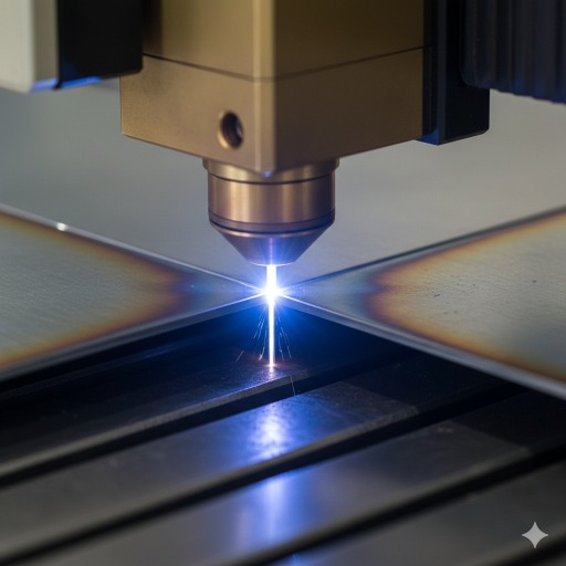
(AI generated) Sheet metal cutting parameters shown through kerf width and edge condition detail
What are the Main Parameters in the Sheet Metal Cutting Process?
Regardless of the technology used, every sheet metal cutting process is governed by a core set of parameters. These variables determine dimensional stability, edge integrity, and assembly performance.
The main parameters include:
- Material type and thickness
- Cutting speed and applied force
- Kerf width and heat input and Edge quality
- Tolerance stack-up across features
Ignoring them is where most cutting problems begin.
1. Material Type and Thickness
Material composition changes everything.
Mild steel, stainless steel, aluminum, and copper all respond differently to the same sheet metal cutting methods. Thermal conductivity, reflectivity, and hardness affect how energy transfers into the material.
Thickness amplifies those effects.
Thin sheet reacts quickly to heat input and can distort if energy density is too high. Thick plate requires more power and introduces wider kerf and potential taper.
Engineers specifying cutting accuracy and tolerances must account for thickness realistically.Tolerances in the range of ±0.05 mm may be achievable on thin stainless steel under controlled laser conditions. The same tolerance on thick structural steel may require secondary machining.
Material choice is not just structural. It directly influences the achievable precision of the sheet metal cutting process.
2. Cutting Speed and Force
Speed and force are often treated as productivity settings, but they are quality variables.
In mechanical sheet metal cutting, excessive force can increase burr height and accelerate tool wear. In thermal cutting, excessive speed may cause incomplete penetration or edge roughness. Too slow, and heat input rises, increasing distortion.
There is always a balance point where:
- Edge quality stabilizes
- Tool wear remains predictable
- Tolerance capability stays within the target
- Experienced operators tune parameters not for maximum speed, but for stable output over time.
3. Kerf Width, Heat Input, and Edge Quality
Kerf width, the material removed during cutting, directly influences dimensional accuracy.
In thermal sheet metal cutting methods, kerf width varies with power level, focus, gas type, and travel speed. In waterjet systems, it depends on nozzle diameter and abrasive flow rate.
Heat input affects:
- Microstructural changes
- Residual stress
- Edge hardness
- Distortion in thin profiles
Even when tolerance capability is met dimensionally, excessive heat can cause downstream forming cracks or weld inconsistency.
Edge quality is not just cosmetic. It influences fatigue life, coating adhesion, and assembly fit.
4. Tolerance Stack-Up in Sheet Metal Parts
One area rarely discussed in blogs is tolerance stack-up.
A single sheet metal cutting process might hold tight tolerances. But when multiple features interact, holes, slots, bends, small deviations accumulate.
For example:
- A slightly oversized kerf
- Minor hole position shift
- Bend radius variation
Individually, these deviations may fall within tolerance. However, combined, they can create assembly misalignment.
Engineers should evaluate tolerances not just per feature, but across the full part geometry. This is especially critical when specifyingrepeatable tolerance control for multi-component assemblies.
The cutting stage sets the baseline. Every downstream operation builds on it.
Sheet Metal Cutting Accuracy and Tolerances
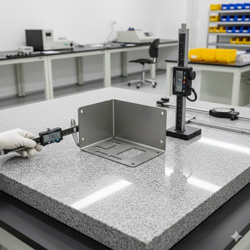
(AI generated) Measuring sheet metal cutting accuracy and tolerances in an industrial inspection area
Cutting accuracy and tolerances are rarely limited by machine capability alone. In most industrial environments, variation comes from material behavior, parameter drift, and how the process is controlled over time.
A laser rated for high precision does not automatically produce high-precision parts. Accuracy is the result of stable inputs and disciplined verification.
For engineers, the key is understanding what influences variation, and what can realistically be controlled within a given sheet metal cutting process.
Factors Affecting Accuracy
Several variables influence precision performance.
Material variability.
Thickness variation across a sheet can change energy absorption in thermal sheet metal cutting methods. Even slight differences affect kerf width and edge straightness.
Machine calibration.
Axis backlash, focus drift, worn nozzles, or inconsistent assist gas pressure gradually reduce precision. These shifts are subtle but measurable over large batches.
Thermal distortion.
In laser and plasma operations, localized heat introduces stress. Long, narrow parts are especially prone to slight warping if nesting and cutting sequence are not balanced.
Tool wear.
In mechanical sheet metal cutting tools, die clearance changes as edges dull. Burr height increases before dimensional deviation becomes obvious.
Programming strategy.
Lead-ins, cut direction, and sequencing influence edge quality and dimensional stability. Experienced programmers often adjust tool paths to reduce cumulative stress.
Precision is not just about the machine, it’s about system stability.
Measuring and Maintaining Tolerances
Maintaining sheet metal cutting accuracy and tolerances requires consistent measurement, not assumption.
Common verification methods include:
- Digital calipers and micrometers for basic dimensional checks
- Optical comparators for profile validation
- Coordinate measuring machines (CMM) for complex geometry
- Flatness gauges for distortion detection
For higher-volume production, statistical process control is often applied. Monitoring deviation trends allows adjustments before parts move outside tolerance.
In thermal sheet metal cutting methods, periodic focus checks and kerf measurement help maintain dimensional consistency. In mechanical systems, scheduled tool inspection prevents progressive drift.
The goal is not perfection on one part. It is repeatable across hundreds or thousands.
When Sheet Metal Cutting Is Not the Best Choice
Despite its versatility, sheet metal cutting is not ideal in every situation. In some cases, alternative manufacturing methods produce better structural or dimensional results.
Very Thick Plate Applications
As thickness increases, certain sheet metal cutting methods become less efficient or less precise.
While plasma and high-power laser systems can process thick material, edge taper and heat input increase. For an extremely thick plate, machining processes such as milling may offer better dimensional control and edge perpendicularity.
When structural load paths demand fully square, stress-relieved edges, cutting alone may not be sufficient.
Ultra-Tight Precision Requirements
If tolerances approach those typical of precision machining, particularly in the sub-0.05 mm range on thicker material, the sheet metal cutting process may not meet requirements without secondary operations.
Laser and waterjet systems can achieve strong tolerance capability, but ultra-tight positional accuracy across multiple interacting features often requires finish machining after cutting.
In hybrid manufacturing strategies, cutting establishes shape, machining refines it.
Post-Machining vs Cutting Trade-Offs
In some designs, engineers face a trade-off:
Engineers must decide whether to cut quickly and machine critical features later, or attempt to hold final tolerances during the sheet metal cutting process itself.
For high-precision assemblies, a hybrid approach is often more stable. Cutting defines the profile efficiently. Machining ensures exact hole location, bearing fits, or alignment features.
Choosing the right path depends on volume, material cost, and functional requirements, not just machine capability.
The right sheet metal cutting tools and methods make the difference between parts that simply look correct, and parts that assemble correctly, perform reliably, and reduce downstream rework.
Key Takeaways
-Sheet metal cutting is a foundational fabrication process that affects forming and assembly quality.
-Laser cutting provides high precision for thin to medium materials.
-Plasma cutting is efficient for thicker steel applications.
-Waterjet cutting avoids heat-affected zones.
-Tolerance stack-up must be considered across interacting features.
-Process control determines repeatability more than machine rating.
FAQs
What are the main types of sheet metal cutting?
The primary types of sheet metal cutting include laser cutting, plasma cutting, waterjet cutting, and mechanical methods such as shearing and punching. Each differs in how material is removed and in achievable cutting accuracy and tolerances.
Which sheet metal cutting method is most accurate?
Laser and waterjet systems generally offer the strongest sheet metal cutting accuracy and tolerances, especially for complex profiles. However, achievable precision depends on material type, thickness, and machine condition.
How do I choose the right sheet metal cutting process?
Consider material type, thickness, production volume, required tolerances, edge quality requirements, and downstream operations such as bending or welding.
Can sheet metal cutting achieve tight tolerances without machining?
For many industrial parts, yes. But when tolerances approach precision machining levels, especially for hole position or bearing fits, secondary machining may be necessary.
Does thickness affect sheet metal cutting accuracy?
Yes. As material thickness increases, kerf width, taper, and heat input typically increase as well, which can affect dimensional precision.
Popular Articles
• 9 Sheet Metal Cutting Problems and Solutions
• Hole cutting in sheet metal: techniques, tolerances and applications
• Introduction to Sheet Metal Processing: Techniques and Tools for Precision
• Bending and Forming Technology in Sheet Metal Processing
• Laser cutting technology in sheet metal processing
Keep Learning
Ultrasonic Welding Guide: How It Works, Materials, Applications, and Benefits
Key Takeaways - Ultrasonic welding uses high-frequency mechanical vibrations to create solid-state welds without melting materials - It works exceptionally well for thermoplastics and many metals, especially dissimilar combinations - The process is fast, clean, and requires no additional adhesives or fillers - Different applications require specific frequency and power configurations - Initial equipment costs are higher, but operating costs are typically lower than alternative methods Introduction Ult......
Hot Rolled vs Cold Rolled Steel: Key Differences, Cost, and Applications
Key Takeaways • Hot rolled vs cold rolled steel comes down to processing history: hot rolled steel is shaped at high temperature, while cold rolled steel is further processed at room temperature for better surface finish and tighter tolerances. • In sheet metal applications, cold rolled steel is usually preferred for enclosures, panels, and precision parts because it offers smoother surfaces and more consistent thickness. • Hot rolled steel is typically better for structural frames, supports, and heav......
Aluminum vs Stainless Steel: Which Sheet Metal Material Is Better?
Note • Aluminum vs stainless steel is not a one-answer choice; the better material depends on weight, strength, corrosion exposure, fabrication method, and total cost. • Aluminum is much lighter, easier to machine, and often less expensive, making it a strong choice for enclosures, panels, and weight-sensitive sheet metal parts. • Stainless steel offers higher absolute strength, better stiffness, and stronger corrosion resistance in harsh environments such as marine, chemical, and food-processing appl......
Metal Mesh Sheets: Types, Sizes, Materials & Custom Fabrication Guide
What Is a Metal Mesh Sheet? (AI generated) metal mesh sheet showing precise grid structure A metal mesh sheet is a material formed by interlacing, welding, or expanding metal into a network of controlled openings. It is widely used where airflow, visibility, or weight reduction is required without sacrificing structural support. A metal mesh sheet is a sheet formed by interlacing, welding, or expanding metal into a network of openings. Those openings are controlled. Size, spacing, and pattern all affe......
Anchor Fasteners for Sheet Metal: Best Types for Concrete and Industrial Use
What is an Anchor Fastener in Sheet Metal (AI generated) Technician securing a sheet metal enclosure Even the most precisely engineered sheet metal part is useless if it isn’t secured properly. In a real-world installation, parts don't exist in a vacuum. Enclosures have to be bolted to shop floors, brackets have to carry heavy piping, and panels have to withstand constant machine vibration. The stability of the entire assembly depends on how it is connected to the base material, usually concrete or ma......
Sheet Metal Deburring: Methods, Tools & How to Deburr Metal and Aluminum
(AI generated) Sheet metal production workflow In this guide, we’ll cover: - What sheet metal deburring is and why it matters - Common burr formation mechanisms - Deburring methods and their trade-offs - How to deburr different metals effectively - Design tips to reduce burr formation Sheet Metal Deburring Methods (Quick Comparison) Method Best For Speed Notes Manual Small jobs Slow Precise, low cost Abrasive Belt Flat sheets Fast Uniform finish Brush Light burrs Fast Good for deburring aluminum Vibra......