CNC Dovetail Workholding: How It Works, Design Rules, and When to Use It
16 min
- What Is CNC Dovetail Workholding
- How CNC Dovetail Workholding Secures a Part
- Tools Used in CNC Dovetail Workholding
- Dovetail vs Traditional Workholding Methods
- When Should You Use CNC Dovetail Workholding
- Design Guidelines for Dovetail CNC Machining
- Machining Strategy for Dovetail Workholding
- Cost and Setup Trade-Offs
- Fixture Types and System Options
- Typical Applications of Dovetail Workholding
- Conclusion About CNC Dovetail Workholding
- FAQ About Dovetail Workholding
CNC dovetail workholding is a fixturing method that holds parts using an angled dovetail feature machined into the workpiece. It enables full top-side access, reduces repositioning, and improves machining accuracy in multi-face operations. It is commonly used for small precision parts, prototypes, and complex geometries.
CNC dovetail is used when standard clamping limits access and stability. It allows multiple faces to be machined in a single setup while maintaining stable constraints. This method is common in precision machining, where repositioning increases error risk.
In many cases, vise clamping blocks tool access or deforms thin parts. Dovetail workholding solves this by holding the part through a bottom-engaging angled interface that constrains both vertical lift and lateral movement via wedge contact surfaces. It uses a machined angled feature that locks into a matching fixture. This approach improves rigidity and reduces the need for multiple setups.
From a practical engineering view, dovetail workholding is not just a fixture choice. It directly affects part design, machining sequence, and material allowance. You must plan the dovetail feature early in the process. Poor planning can lead to weak holding or excess stock waste.
This method works best when you need full top-side access. It is useful for small parts, multi-face machining, and tight tolerance work. However, it also introduces trade-offs in setup time and material removal. Engineers must evaluate these factors before using them.
This article covers:
- How dovetail workholding secures parts during machining.
- How it compares with vise and soft jaw clamping.
- When it improves machining efficiency and stability.
- Design rules for reliable dovetail features.
- CNC Machining strategies to avoid vibration and errors.
- Cost trade-offs and setup considerations.
- Common fixture systems and practical applications.
What Is CNC Dovetail Workholding
Dovetail workholding is a CNC fixturing method that secures a part using a machined angled dovetail feature instead of top-down clamping.
The fixture engages this geometry from below, creating a mechanical wedge lock that resists lifting and side movement during cutting. It is mainly used in multi-face machining or precision parts where full top access and reduced repositioning are required. The method improves setup stability but requires early design integration into the part geometry and machining sequence.
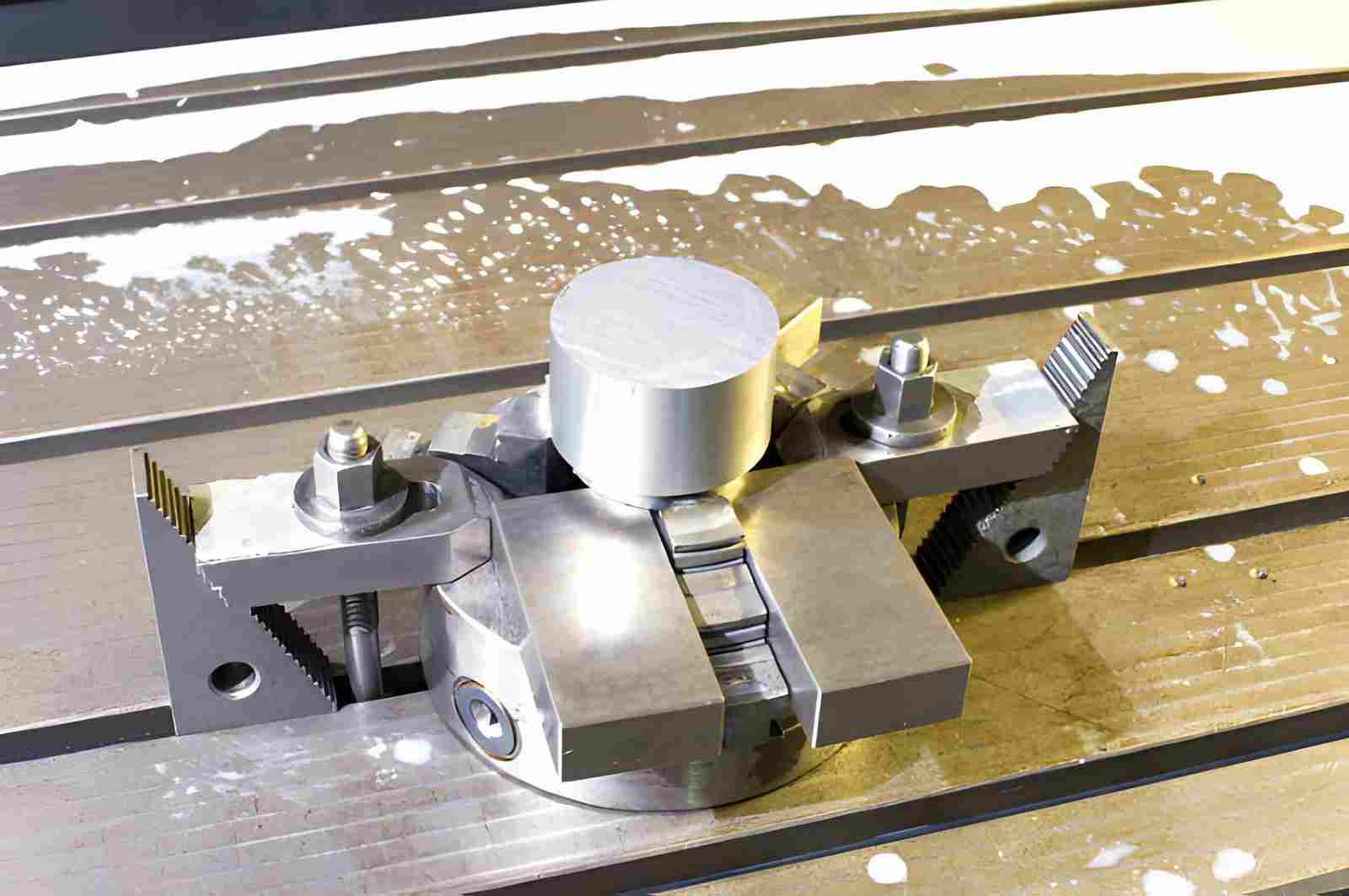
The image shows a CNC machining table with a billet secured using dovetail clamping workholding. (iStock)
How CNC Dovetail Workholding Secures a Part
Dovetail workholding secures a part through angled mechanical contact. The geometry redirects cutting forces along angled contact surfaces, increasing normal force and resistance to lift. This creates a stable constraint during machining.
Creating the Dovetail Feature in the Workpiece
The dovetail feature is a pre-machined, angled groove that forms the holding interface between part and fixture.
- A CNC dovetail cutter machines the angled groove in one setup.
- Common included angles range from 45° to 60° based on load requirements.
- Groove depth often falls in the 2–8 mm range for small parts, depending on load and material.
- Extra stock is added around the feature to avoid damage to functional surfaces.
How the Fixture Engages and Locks the Part
The fixture uses matching angled jaws that slide into the dovetail and create mechanical locking through contact pressure.
- The fixture jaw enters the groove with controlled alignment from one direction.
- Wedge action increases contact force as the jaw seats deeper.
- Full surface contact prevents vertical lift during cutting load.
- Hardened steel jaws maintain repeatability over multiple production cycles.
Force Direction and Constraint Stability
Cutting forces act along the angled surfaces and convert into a clamping force, which improves stability instead of loosening the part.
- Downward cutting force pushes the part into the fixture base.
- Angled walls convert vertical force into horizontal locking pressure.
- Side cutting loads are distributed across the full contact faces.
- Proper angle selection prevents part slipping under vibration and load.
Tools Used in CNC Dovetail Workholding
Dovetail workholding depends on both the cutter used to generate the feature and the hardware used to engage it. Tool geometry and fixture design must match, otherwise holding strength and repeatability will degrade.
CNC Dovetail Cutters
Dovetail cutters are used to machine the angled groove that forms the clamping interface. The included angle of the cutter must match the fixture geometry to ensure proper contact.
- Common angles are 45° and 60°, selected based on load direction and available contact area
- Smaller angles increase the wedge effect but concentrate stress
- Larger angles reduce stress but require more clamping force
- Cutter rigidity matters — short overhang and solid carbide are typically preferred
In practice, cutter wear directly affects the contact geometry. Even small edge rounding can reduce holding stability in precision setups.
Dovetail Jigs vs Fixtures
Dovetail systems rely on dedicated workholding hardware, which can be implemented as either jigs or fixtures depending on the machining setup.
- Fixtures provide rigid, repeatable positioning and are fixed relative to the machine table
- Jigs may guide tool motion or assist positioning, but are less common in CNC milling setups
- Most dovetail workholding systems function as fixtures rather than true jigs
For production work, fixture repeatability and jaw alignment accuracy have a greater impact on part stability than the dovetail geometry itself.
Dovetail vs Traditional Workholding Methods
The image shows a lathe chuck used for holding workpieces during machining operations. (iStock)
Dovetail workholding secures parts using angled geometric locking. On the other hand, traditional clamping applies vertical or lateral force, which depends more on friction and clamping pressure. This difference affects access, deformation risk, and setup strategy in real machining.
Limitations of Vise Clamping and Top-Down Holding
Close-up of a manual machine vise used for securing workpieces during machining. (iStock)
Vise and top-down systems rely on friction-based grip. This can create instability under heavy cutting loads or on thin-walled parts.
- Clamping force acts normal to the surface, increasing deformation risk in thin sections.
- Friction-based holding allows micro-slip under high radial cutting forces.
- Jaw contact blocks tool access on at least two or three faces.
- Re-clamping introduces datum shift, typically in the range of 0.01 to 0.05 mm.
If you need a clearer understanding of how fixtures differ from jigs in CNC machining workflows, see this breakdown of jigs vs fixtures.
Soft Jaws vs Dovetail: Setup and Flexibility
Soft jaws improve part conformity by machining custom profiles, while dovetail systems lock geometry into the fixture itself for repeatable engagement.
- Soft jaws require re-machining for each new geometry, adding 10 to 30 min setup time per batch.
- Dovetail geometry is integrated into the part, reducing fixture rework for repeated runs.
- Soft jaws distribute load across a larger area, reducing localized stress on delicate parts.
- Dovetail engagement resists axial lift forces directly through 45–60° wedge conversion.
Dovetail Workholding vs Vise Clamping vs Soft Jaws
| Parameter | Vise / Top Clamping | Soft Jaws | Dovetail Workholding |
|---|---|---|---|
| Holding Principle | Friction + normal force | Conformal friction contact | Geometric wedge locking |
| Typical Clamping Force | 5 to 25 kN (manual vise range) | 10 to 40 kN (hydraulic/manual) | Force is resolved into axial and normal components via wedge geometry (not amplified) |
| Axial Lift Resistance | Medium | High | Very High (geometry locked) |
| Setup Time per New Part | 2 to 5 min | 10 to 30 min | 15 to 45 min (initial feature design required) |
| Repositioning Error | 0.01 to 0.05 mm typical | 0.005 to 0.03 mm typical | <0.01 mm in controlled setups |
| Tool Access | Limited side access | Moderate | High (top and multi-face access) |
| Thin Wall Risk | High (jaw pressure) | Medium | Low (no top compression load) |
| Best Cutting Condition | General milling/drilling | Custom part batches | Multi-face precision machining, single setup strategy |
The right choice depends on part geometry, setup frequency, and access requirements. Standard clamping works well for straightforward operations, soft jaws help when shape-specific support is needed, and dovetail workholding becomes more valuable when setup reduction, repeatable re-engagement, and multi-face access are priorities.
For parts that need stable re-clamping and broader tool access across multiple operations, dovetail workholding often delivers the most process control.
When Should You Use CNC Dovetail Workholding
You should use CNC dovetail workholding when full top access, multi-face machining in a single setup, and high positional accuracy are required.
Dovetail workholding is useful when a part needs strong stability with full top-side access in a single setup. It helps reduce repositioning errors and improves control in precision machining. However, it is not suitable for every geometry or cutting condition.
Ideal Scenarios for Dovetail Machining
Dovetail workholding is practical when stability and access are more important than setup speed.
- It supports multi-face machining in one setup.
- It works well for small to medium precision parts.
- It improves repeatability in batch production.
- It allows full access to the top machining surfaces.
When It Introduces Risk or Limitations
Dovetail systems can create problems when part geometry is weak or cutting forces are high.
- It can damage thin walls during feature cutting or clamping.
- It reduces usable space for functional design features.
- Stability also drops under heavy or interrupted cutting conditions.
- It increases machining time for the dovetail feature itself.
A Simple Decision Logic for Engineers
Engineers should select dovetail workholding based on access needs, part strength, and tolerance demand.
- Use it when one setup improves accuracy and alignment.
- Avoid it for fragile or thin-walled components.
- Choose it when repositioning errors affect the final quality.
Design Guidelines for Dovetail CNC Machining
Dovetail workholding depends on part geometry to provide a reliable clamping interface. Design decisions made at this stage directly determine whether the part can be held securely without deformation or failure.
Minimum Thickness and Structural Support
The material around the dovetail must be thick enough to carry both cutting loads and clamping forces.
For aluminum parts, a minimum thickness of around 3–5 mm is typically required near the dovetail feature.
For steel, this usually increases to 5–8 mm due to higher cutting forces.
Thin sections near the dovetail increase the risk of cracking or local deformation during both machining and clamping.
Placement of the Dovetail Feature
The dovetail should be located in a structurally stable region of the part, not near functional or cosmetic surfaces.
Keep sufficient distance from thin ribs, sharp corners, or sealing features.
Positioning the dovetail close to rigid mass improves load transfer and reduces local stress concentration.
Poor placement often leads to vibration or part damage, even if the machining strategy is correct.
Stock Allowance and Removal Planning
The dovetail feature requires additional stock that will be removed later in the process.
Allow extra material around the clamping interface to protect the final geometry.
This stock must be planned early. It can interfere with part dimensions or functional surfaces.
Uneven or insufficient allowance can result in unstable clamping or rework.
Designing for Load Path Stability
The dovetail geometry should align with how forces are transmitted during machining.
Avoid designs where cutting forces act to pry the part away from the fixture.
Keep the clamping interface aligned with the primary load direction whenever possible.
If the geometry does not support stable load transfer, no machining adjustment will fully compensate.
Machining Strategy for Dovetail Workholding
Dovetail workholding depends on a planned machining sequence because the part itself becomes part of the fixture. Process order, cutting load, and fixture design directly affect stability and accuracy in multi-stage operations.
Tool Selection and Cutting Considerations
Tool choice affects feature accuracy, tool wear, and stability during dovetail machining.
- Use carbide dovetail cutters for consistent edge stability.
- Keep cutter angles matched to fixture angle, typically 45° or 60°.
- Limit radial engagement to 20 to 40% of the tool diameter during roughing.
- Use short overhang tools, ideally below 4× tool diameter for rigidity.
Load Distribution Across Operations
Cutting loads must be balanced across roughing, semi-finishing, and finishing stages to avoid distortion.
- Roughing removes bulk material, leaving 0.3 to 0.8 mm stock.
- Semi-finishing stabilizes geometry and reduces stress concentration.
- Finishing applies light cuts, typically 0.05 to 0.2 mm depth of cut.
- Uneven load distribution can cause taper or misalignment in the dovetail seat.
Machining Sequence and Process Order
The order of operations affects how stable the part remains during machining.
The dovetail feature is typically machined before final finishing, so it can be used for subsequent setups.
Later operations should avoid introducing forces that weaken the clamping interface.
Incorrect sequencing can reduce holding strength even if the geometry is correct.
Controlling Vibration and Stability During Cutting
Stability during machining depends on how cutting forces interact with the fixture and part.
Reducing feed or depth of cut may be necessary when vibration appears.
Consistent coolant application helps manage heat and maintain cutting conditions.
These adjustments do not fix poor design, but they can stabilize a well-designed setup.
Cost and Setup Trade-Offs
Dovetail workholding changes the cost structure by shifting effort from setup and clamping to design and preparation. It can improve machining efficiency, but it also adds upfront machining and planning costs.
Setup Time vs Machining Efficiency
Dovetail systems require more preparation time before cutting starts, but they reduce interruptions during machining.
- Initial setup takes longer due to feature machining in the part.
- Fixture alignment requires controlled engagement before cutting.
- Once set, machining runs faster with fewer repositioning steps.
- Reduced reclamping improves consistency in tight-tolerance work.
When It Reduces Total Cycle Time
Dovetail workholding becomes efficient when multiple operations are completed in one setup.
- Single setup machining removes repeated alignment steps.
- Multi-face machining reduces total machine idle time.
- Batch production benefits from stable repeat positioning.
- Complex parts save time by avoiding secondary fixturing operations.
Hidden Costs and Material Waste
Cost savings in machining can be offset by additional material and preparation requirements.
- Extra stock is required to machine the dovetail feature.
- Material loss increases due to non-functional clamping geometry.
- Tool wear increases during dovetail cutting operations.
Fixture Types and System Options
Dovetail workholding systems are available in different configurations based on production needs. Each system changes how easily you can scale, adjust, and integrate the fixture into machining workflows.
Standard Dovetail Fixture Systems
Standard systems use fixed geometry and predefined jaw designs for consistent machining.
- Fixed dovetail angle is commonly set at 45° or 60°.
- Designed for repeat production with stable positioning accuracy.
- Offers high rigidity for consistent cutting loads.
- Requires a dedicated setup for each part design.
Modular and Expandable Setups
Modular systems allow adjustment and reuse across different parts and batch sizes.
- Interchangeable jaws support multiple component geometries.
- Base plates use grid or slot layouts for flexible positioning.
- Suitable for prototype and low to medium production runs.
- Provides balanced rigidity with adaptable configuration.
DIY or Low-Cost Dovetail Solutions
DIY systems use simplified fixture designs for small-scale or experimental machining.
- Machined dovetail pockets are added directly to fixture plates.
- Simple wedge clamps are used for manual locking.
- Low-cost implementation with basic machining requirements.
Typical Applications of Dovetail Workholding
Dovetail workholding is selected when part geometry requires a strong bottom-side constraint and full top access in one setup. It is most effective where repositioning affects alignment and dimensional stability.
Multi-Face Machined Parts
Parts requiring machining on multiple faces benefit from a single stable setup. Dovetail support removes the need for re-clamping and re-alignment.
- Full top surface remains open for uninterrupted tool access.
- Single setup maintains alignment across multiple machined faces.
- Reduced datum shift improves positional accuracy between operations.
- Stable holding supports consistent cutting conditions during all stages.
Complex Small Components
Small and intricate parts often need secure holding without blocking tool paths or damaging thin features.
- Bottom-side engagement avoids obstruction on critical machining faces.
- Irregular shapes become easier to stabilize during cutting.
- Thin sections remain supported against vibration and deflection.
- Secure locking improves control during fine finishing passes.
Prototype and Low-Volume Production
Frequent design changes require flexible fixturing without repeated custom setups.
- Geometry changes can be adapted without a full fixture redesign.
- The setup time is reduced compared to repeated soft jaw machining.
- Repeat positioning remains consistent across short production runs.
Conclusion About CNC Dovetail Workholding
Dovetail workholding is effective when parts need stable bottom-side locking with full top access in a single setup. It reduces repositioning steps and improves alignment control across multiple machining operations. It is mainly used in precision work where setup consistency directly affects final accuracy.
It should be avoided when part walls are thin or when cutting loads exceed safe engagement limits. In such cases, standard clamping or custom fixtures provide better stability.
Dovetail fixtures are often CNC machined to match specific part geometry and tolerance requirements. This means the effectiveness of the method depends not only on part design, but also on how the fixture and machining process are developed together.
At JLCCNC, we design custom dovetail fixtures and machining strategies based on your part geometry, material, and tolerance requirements.
Whether you need prototype support or batch production, our team ensures stable workholding and efficient machining from the first setup.
Upload your CAD file to get a fast quote starting from $1, with lead times as short as 3 days.
FAQ About Dovetail Workholding
Q: What is a dovetail in CNC machining?
A dovetail in CNC machining is an angled slot or feature cut into a part that allows the fixture to grip it from below. This geometry creates a mechanical lock that improves stability during machining.
Q: How deep should a dovetail cut be?
Dovetail depth depends on part size, material, and cutting load. In most precision parts, depth stays between 2 mm and 8 mm. Harder materials and higher loads may require deeper engagement, but excessive depth should be avoided to prevent weakening the part.
Q: Is CNC dovetail workholding better than a vise?
Dovetail workholding is not a direct replacement for a vise. It is better for multi-face machining and high-precision setups where repositioning errors must be reduced. A vise is more practical for general machining and fast setup work.
Q: Can CNC dovetail workholding be used for steel parts?
Dovetail workholding can be used for both aluminum and steel. Steel requires stronger cutting tools and more rigid fixtures due to higher cutting forces. Aluminum is easier to machine but needs careful control to avoid deformation during engagement.
Q: When should you avoid dovetail workholding?
Avoid it when parts have thin walls, weak sections, or require heavy interrupted cutting. It is also unsuitable when setup speed is more important than positioning accuracy.
Q: How much stock should be reserved for a dovetail?
Typically, 0.3–0.8 mm per side is reserved for finishing. Larger allowances may be needed for steel or deep engagement features.
Q: Does dovetail workholding affect part accuracy?
Yes. It can improve positional repeatability by reducing reclamping, but accuracy still depends on machine rigidity, fixture condition, and cutting stability.
Popular Articles
• Cutting with Precision: A Comprehensive Guide to CNC Water Jet Technology
• CNC Coolant Explained: Types, Maintenance & Safety
• Rake Angle in Machining: Machinists’ Guide to Perfect Cuts
• What Steps Are Taken To Minimize Waste In CNC Machining Processes?
• How EDM Wire Cutting Works: Complete Guide to Precision CNC Wire Cutting
Keep Learning
Chatter in Machining: Causes, Effects, and How to Reduce It
CNC milling operation producing visible chatter marks on an aluminum workpiece Quick Chatter Diagnosis Checklist Symptom Most Likely Cause First Action High-pitched squeal Regenerative chatter Change spindle speed ±15% Chatter only in deep pockets Excessive tool overhang Shorten tool Chatter on thin walls Low workpiece rigidity Improve fixturing Chatter after tool replacement Runout / holder issue Check tool holder Chatter only during finishing DOC too small / rubbing Increase feed or adjust speed It ......
What Is Tool Offset in CNC? Types, Setup & Best Practices
CNC tool offset setup with measurement overlay Key Takeaways CNC offsets connect programmed intent with actual cutter position. Length data guides Z-axis depth control. Radius data protects part size during contour milling. Geometry values define the cutter's measured baseline. Wear values support fine correction during production. Verified data lowers scrap risk before full machining. Good offset habits protect tools, fixtures, and parts. In the context of CNC machining, tool offset is the quiet setu......
Trochoidal Milling: Complete Guide to High-Efficiency CNC Machining
Key Takeaways Trochoidal milling combines circular cutter motion with continuous forward feed. The cutter normally engages 5 to 20% of its diameter instead of making a full-width cut. A smaller engagement angle limits force changes during slotting and pocket roughing. Low radial engagement often allows greater axial depths of cut than conventional slot milling. CAM software calculates the circular path automatically from the selected machining parameters. This strategy is widely applied to titanium, s......
What Is Die Casting? Process, Materials, and Applications
Key Takeaways Die casting is a metal casting process that forces molten metal into a reusable steel mold under high pressure, producing parts with tight tolerances and good surface finish at high volume. Aluminum die casting is the most common form by far, thanks to its combination of light weight, decent strength, and good corrosion resistance. The die casting process runs through mold preparation, injection, cooling, and ejection in a cycle that can repeat every few seconds to minutes depending on p......
First Angle vs Third Angle: Understanding Orthographic Projection Methods
Key Takeaways Orthographic projection is the system that lets a 3D part be represented through multiple 2D views, front, top, side, and so on. First angle projection and third angle projection are the two standard methods for arranging those views, and they place views in opposite positions relative to the object. First angle projection is the ISO standard used across most of Europe, India, China, Russia, and many other countries following ISO standards Third angle projection is the standard in the Un......
Micro EDM Machining: Capabilities, Materials, and Applications for Precision Components
Key Takeaways About Micro EDM Machining Only electrically conductive materials can be machined. Hole diameters can reach below 50 μm on specialized equipment. The process produces almost no mechanical cutting force, making it suitable for thin or delicate features. Surface integrity still requires attention because recast layers and heat-affected zones may remain after machining. Micro EDM is often combined with CNC machining, with milling producing the main geometry before EDM finishes critical micro......