CNC Enclosure Design for Machining: Cost, Materials, and Production Considerations
17 min
- What Is a CNC Machined Enclosure
- When Should You Use a CNC Enclosure Instead of Sheet Metal?
- CNC Machine Enclosure Design: Key Decisions Before Machining
- Common CNC Enclosure Design Mistakes (and How to Avoid Them)
- CNC Enclosure Materials: Choosing Aluminum, Steel, and Plastics for CNC Enclosure Design
- CNC Enclosure Machining Cost: What Drives Price and Lead Time
- CNC Enclosure Tolerances and Surface Finish Requirements
- How to Choose a CNC Enclosure Manufacturer
- Custom CNC Enclosure Machining Services at JLCCNC
- FAQ
What Is a CNC Machined Enclosure
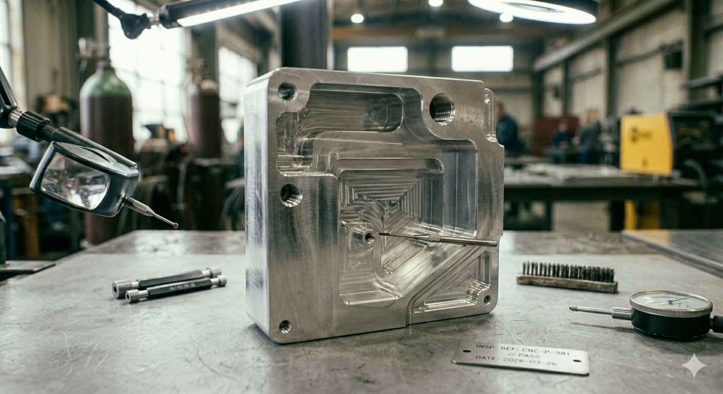
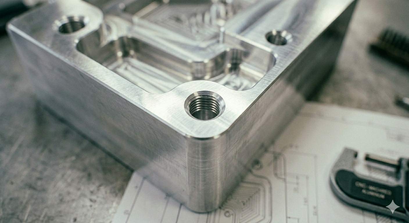
(AI generated) CNC-machined aluminum enclosure with internal cavities
A CNC machined enclosure is a housing manufactured by removing material from a solid block using milling or turning operations. The process creates accurate internal cavities, threaded features, and sealing surfaces.
Engineers use CNC machining when the enclosure must hold electronics, sensors, or mechanical assemblies with tight alignment requirements. Typical examples include control modules, instrumentation housings, and CNC electronics enclosure assemblies used in industrial equipment.
CNC machining makes it easier to produce thick, monolithic wall sections and integrated structural features that are difficult to achieve in bent sheet metal parts. This rigidity improves vibration resistance in many machine environments.
CNC vs 3D Printing vs Sheet Metal Enclosures
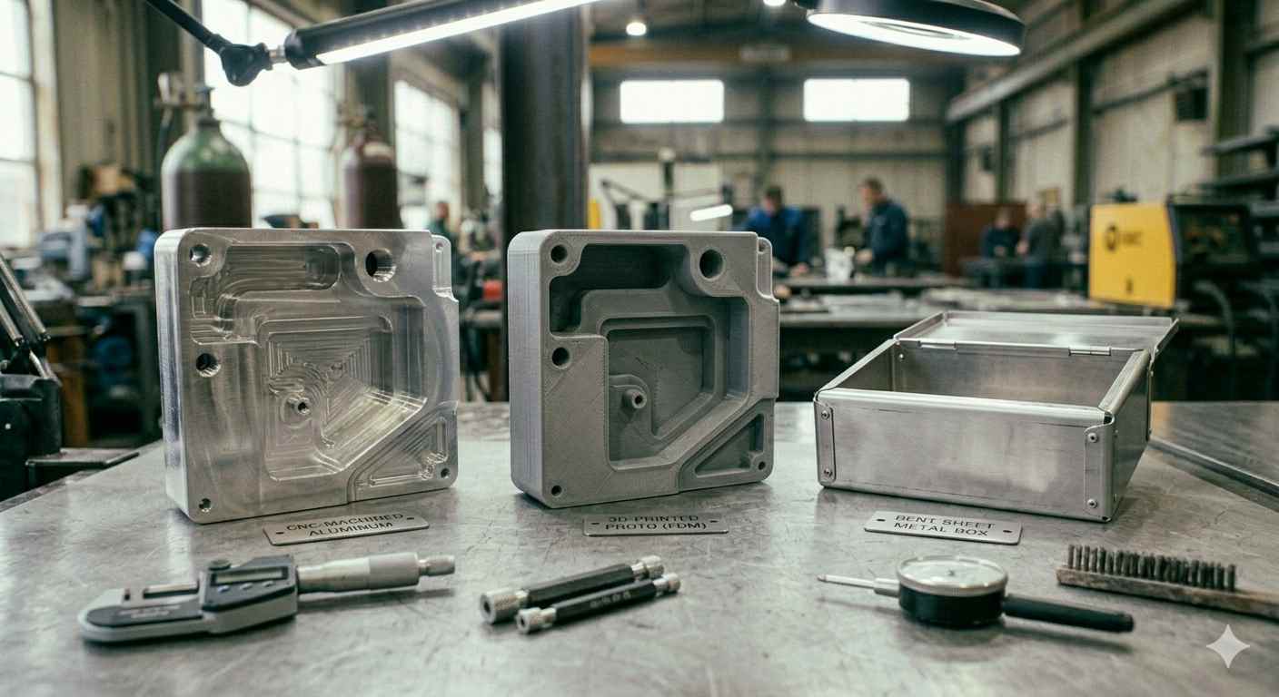
(AI generated) Comparison of CNC, 3D-printed, and sheet metal enclosures
Manufacturing Method | Typical Use Case | Advantages | Limitations |
|---|---|---|---|
CNC Machining | Precision housings, electronics enclosures, structural parts | Tight tolerances, strong materials, accurate internal features | Higher cost for large parts |
3D Printing | Rapid prototypes, lightweight housings | Fast iteration, complex shapes possible | Lower strength, rough surface finish |
Sheet Metal Fabrication | Large equipment enclosures, panels | Low cost at scale, efficient for simple shapes | Limited internal geometry |
When Should You Use a CNC Enclosure Instead of Sheet Metal?
Sheet metal works well for large housings. It bends quickly and scales well in production. Still, some sheet metal enclosure designs push past what forming processes can handle.
A CNC machine enclosure design becomes practical when internal geometry matters. Machining allows deep cavities, precise connector cutouts, and rigid mounting surfaces in a single part.
Electronics housings are a common example. A CNC electronics enclosure often includes threaded bosses, O-ring grooves, and connector ports that must align within small tolerances.
Design teams also choose CNC machining when the enclosure doubles as a structural component. A machined aluminum housing can carry a load while protecting electronics inside.
At JLCCNC, these enclosures are typically machined from aluminum or engineering plastics using multi-axis CNC mills, which makes it possible to produce deep internal cavities, connector cutouts, and threaded mounting features within tight tolerances.
For a deeper comparison, see our guide:
CNC Machining vs Sheet Metal: Which is Better for Enclosures?
CNC Machine Enclosure Design: Key Decisions Before Machining
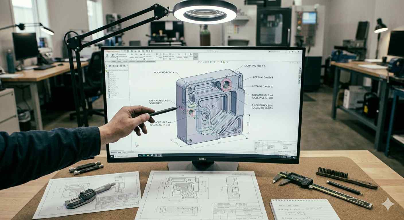
(AI generated) CNC enclosure CAD model
Most CNC enclosure problems appear before the first tool touches material. The CAD model may look clean. Machining, though, tells a different story. See our guide on how to prepare CAD files for CNC machining for a more detailed file submission checklist.
Tool access often becomes the limiting factor. End mills need room to enter cavities, clear chips, and maintain rigidity. If the geometry blocks tool access, machining time rises fast. Sometimes the part cannot be machined at all without redesign.
Early design decisions shape cost and feasibility. Wall thickness, cavity depth, and feature placement determine how many setups the shop must run. They also determine whether standard tooling works or special tools become necessary.
Engineers designing CNC machine enclosures usually focus on three questions first. How thick are the walls? How deep are the cavities? Where do the critical features sit relative to tool access?
Small changes in those areas often prevent redesign before the first machining run.
Wall Thickness & Internal Cavities
Wall thickness sets the structural strength of a CNC electronics enclosure. It also affects machining stability.
Thin walls vibrate during cutting. That vibration leaves tool marks and dimensional variation. Aluminum enclosures commonly use a wall thickness of around 2 to 3 mm for small housings, though deeper cavities or larger parts often require thicker sections. Larger parts often require thicker sections to maintain rigidity during machining.
Internal cavities introduce another constraint. Deep pockets require long cutting tools. Long tools flex more under load. Surface finish suffers, and machining time increases.
A common redesign happens when cavity depth exceeds the practical tool reach. Engineers may split the enclosure into multiple sections or reduce cavity depth to maintain tool stability.
Critical Features and Mounting Considerations
Mounting features control how the enclosure integrates with the rest of the system. Threaded holes, alignment pins, connector openings, and sealing grooves must land in precise locations.
These features should stay accessible from the primary machining direction whenever possible. Features buried deep inside a cavity often force additional setups or specialized tooling.
Engineers designing a CNC mill enclosure also need to consider internal clearance for components. Tight internal layouts sometimes block tool access for drilling or tapping operations.
A simple rule helps here. If a tool cannot approach a feature directly from one machining direction, the design may require extra setups.
Split vs One-Piece Enclosure Design
A single-piece enclosure looks elegant in CAD. Manufacturing often favors a split design.
Two-piece housings expose internal features during machining. That access allows standard end mills to reach mounting bosses, connector cutouts, and sealing surfaces without deep cavity machining.
One-piece designs can still work. They simply require more machining steps and additional setups. For larger CNC machine enclosures, splitting the housing into top and bottom halves often reduces machining time and simplifies assembly.
Engineers sometimes resist split designs early in development. Later revisions frequently add them once machining constraints become clear.
CNC Enclosure Design Rules of Thumb
- Minimum wall thickness: 2–3 mm for aluminum enclosures
- Internal corner radius ≥ tool radius
- Keep cavity depth within 2–3× tool diameter
- Avoid features that block tool access
- Reduce setups whenever possible
Common CNC Enclosure Design Mistakes (and How to Avoid Them)
Most enclosure issues show up during the first prototype run. The CAD model works. The machining program runs. Then the physical part reveals problems nobody expected.
We ran into this while machining a compact control enclosure for a small automation module. The electronics fit perfectly in CAD. The first machined housing told a different story. Tool access was tight, one cavity caused chatter, and a connector cutout forced an extra setup that doubled machining time.
None of these mistakes were dramatic. They were small design decisions that quietly increased cost and complexity.
Below are the enclosure problems we see most often during CNC machining projects, along with the fixes engineers typically apply after the first iteration.
Design Issue | What Happens During Machining | How We Typically Fix It |
|---|---|---|
Deep narrow cavities | Long tools begin to flex and chatter. Surface finish degrades and cycle time increases because the machine must reduce feed rates. | Increase cavity width or split the enclosure into two halves so tools can reach internal features more directly. |
Internal corners with zero radius | Standard end mills cannot create perfectly sharp internal corners. CAM software compensates with tiny tools, which slows machining dramatically. | Add realistic internal radii that match common tool sizes. Even a 1–2 mm radius can simplify machining. |
Extremely thin walls | Thin sections vibrate under cutting forces. Parts may deform slightly during machining or finishing. | Increase wall thickness or add ribs for stiffness. For aluminum enclosures, slightly thicker walls often reduce machining issues. |
Hidden threaded holes | Holes buried inside deep pockets require long drills or multiple setups. | Relocate threaded holes where they can be reached from the main machining direction. |
Connector cutouts too close to edges | Edge breakout or poor finish occurs when the tool exits thin material. | Add extra material around ports and reduce sharp corner geometry near edges. |
One project we machined recently illustrates how small changes improve manufacturability.
The enclosure contained a deep internal cavity for a PCB assembly. On the first revision, the cavity depth forced a long end mill with limited rigidity. Surface finish inside the pocket looked rough, and machining time increased because the tool had to cut slowly.
Instead of fighting the geometry, we suggested splitting the housing into a top and bottom section. The redesign allowed direct tool access to both halves. Machining time dropped, surface finish improved, and assembly became easier for the client.
Another common issue involves over-specified tolerances. Engineers sometimes apply tight tolerances across the entire enclosure model. In practice, only a few surfaces truly require precision. Mounting holes, sealing grooves, and alignment surfaces matter. Cosmetic walls usually do not.
Relaxing noncritical tolerances reduces machining time without affecting performance.
This kind of design feedback happens often during the quoting stage at JLCCNC. Our engineers review enclosure models before machining begins and flag features that will increase cost or lead time. Many problems disappear with small geometry adjustments early in the design phase.
For customers building prototype electronics housings or custom CNC enclosures, that early feedback usually saves both machining time and redesign cycles.
CNC Enclosure Materials: Choosing Aluminum, Steel, and Plastics for CNC Enclosure Design
Material Category | Machinability | Structural Performance | Corrosion Resistance | Cost Impact | Machining Strategy Considerations | Typical CNC Enclosure Use Cases |
|---|---|---|---|---|---|---|
Aluminum Enclosures | Excellent machinability. Cuts quickly with stable tool life. | Strong for its weight. Good rigidity for most electronics housings and industrial enclosures. | Naturally corrosion-resistant. Often improved further with anodizing. | Moderate material cost but low machining time, making the total cost efficient. | Allows aggressive feed rates and deeper cuts. Standard end mills work well for cavities, threads, and connector cutouts. | Electronics housings, automation controllers, sensor enclosures, lightweight equipment modules. |
Stainless Steel Enclosures | Difficult compared with aluminum. Slower cutting speeds and higher tool wear. | Very high strength and stiffness. Performs well in heavy-duty or harsh environments. | Excellent corrosion resistance, especially in humid, chemical, or marine environments. | Higher machining cost due to slower speeds and increased tool wear. | Requires conservative feeds and speeds. Heat buildup must be controlled to protect tools and maintain surface quality. | Food processing equipment housings, marine electronics, chemical environment enclosures. |
Engineering Plastics | Very easy to machine. Low cutting forces and fast material removal. | Lower structural strength compared with metals, but adequate for many lightweight housings. | Excellent resistance to corrosion and many chemicals. | Lower machining cost due to fast cutting and inexpensive raw material. | Requires careful chip evacuation and temperature control to avoid melting or deformation. | Lightweight electronics enclosures, insulation housings, prototype device casings. |
Also, read our guide on CNC machining materials.
How to Choose Material for a CNC Enclosure
Instead of starting from material categories, engineers usually start from constraints.
When the enclosure includes sealing surfaces or threaded features that must stay stable after machining and finishing, aluminum tends to be selected because the process is predictable and repeatable.
If the enclosure is exposed to aggressive environments or carries mechanical load beyond what aluminum can handle, the decision shifts. At that point, machining cost becomes part of the trade-off rather than the main constraint.
For lightweight housings or electrically isolated designs, plastics enter as an option. The limiting factor is not strength alone, but deformation during machining and long-term stability under load.
CNC Enclosure Machining Cost: What Drives Price and Lead Time
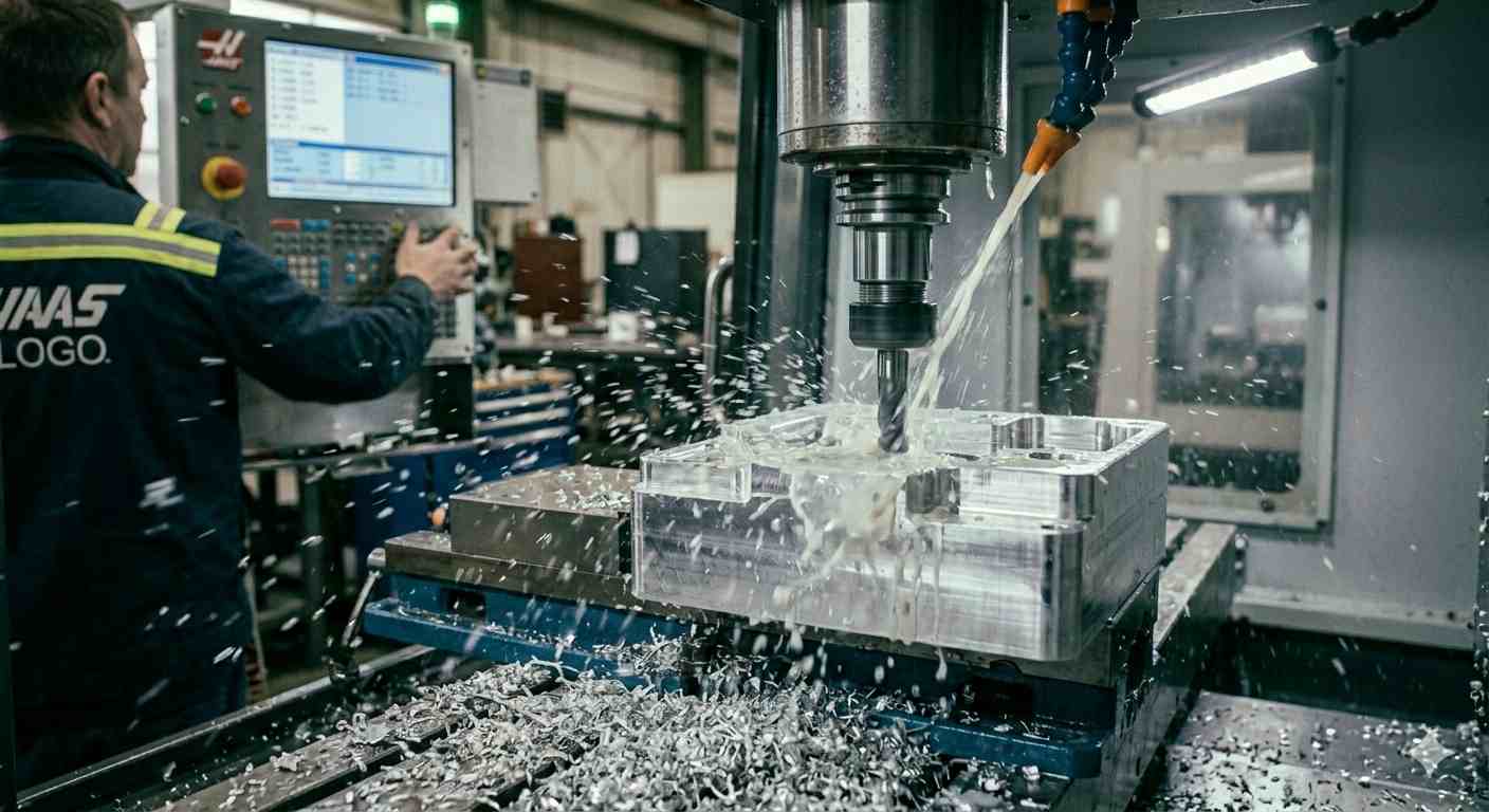
(AI generated) CNC mill cutting aluminum enclosure
CNC enclosure cost rarely comes from material alone. In most projects, machine time and setup complexity drive the final price.
Two enclosure designs may use the same aluminum billet. One machines in thirty minutes. The other runs for several hours because of deeper cavities, additional setups, or post-processing requirements.
Engineers planning a CNC machine enclosure should look beyond overall size. The real cost drivers hide in geometry, feature layout, and finishing requirements.
Geometry Complexity and Hidden Machining Time
Complex geometry increases machining time in ways that are not always obvious in CAD.
Deep cavities require longer cutting tools. Long tools must run at slower speeds to prevent deflection. That alone can double machining time for internal pockets.
Small internal radii create another issue. Standard end mills cannot reach tight corners efficiently. The CAM program switches to smaller tools, which remove material much more slowly.
Toolpath complexity also grows when enclosures contain many internal bosses, threaded holes, or irregular pockets. Each feature forces additional tool movements and sometimes multiple cutting passes.
This is why two enclosures with identical external dimensions can have completely different machining costs.
Number of Setups and Fixturing Constraints
Every time a part changes orientation on the machine, a new setup begins. Each setup requires alignment, probing, and fixturing adjustments.
Simple enclosures may machine entirely from one side. More complex housings often require three or four setups so tools can reach all features.
The setup count directly affects lead time because machines must pause between operations for repositioning and inspection.
Fixturing also becomes more difficult with thin walls or irregular shapes. Parts may require custom fixtures to prevent movement during cutting. Designing and installing those fixtures adds preparation time before machining even starts.
Reducing setups is one of the fastest ways to lower the cost of a CNC electronics enclosure.
Secondary Operations and Surface Requirements
Machining rarely ends when the milling operation finishes. Many enclosures require secondary processes before they are ready for assembly.
Common examples include:
- Thread tapping for mounting hardware
- Deburring and edge finishing
- Surface treatments such as anodizing or bead blasting
- Laser engraving for labels or branding
Each operation adds handling time and scheduling complexity. Surface finishes also introduce additional lead time because parts must move to finishing stations or external coating facilities.
For example, an anodized aluminum enclosure requires additional time for cleaning, chemical processing, and drying before shipment.
From a manufacturing standpoint, enclosure cost usually comes down to three factors: how long the machine runs, how many setups the part requires, and how many finishing steps follow machining.
Read our guide on the most cost-effective metals for CNC machining for a broader material cost comparison.
CNC Enclosure Tolerances and Surface Finish Requirements
(AI generated) CNC aluminum enclosure showing precise surface finish
Tolerance and surface finish decisions affect far more than appearance. In a CNC enclosure, they determine whether components align correctly, seals perform as expected, and the final assembly closes without stress on internal parts.
Many enclosure designs apply tight tolerances across the entire model. That approach increases machining time without improving performance. In practice, only specific surfaces require precision. The rest of the enclosure can tolerate wider tolerances without affecting function.
Understanding where precision matters helps engineers control machining cost while maintaining reliable assembly.
Critical Fits for Assembly and Sealing
Certain features inside a CNC electronics enclosure directly influence how the system assembles.
Mounting holes must align with PCB standoffs and internal components. Connector cutouts must match the dimensions of ports and cable glands. Sealing grooves must maintain consistent depth and width so O-rings compress properly.
If these features drift outside tolerance, assembly problems appear quickly. Screws may not align, connectors may sit crooked, or sealing gaskets may fail to compress evenly.
Because of this, machinists usually hold tighter tolerances on:
- Threaded mounting holes
- Alignment pins and dowel features
- O-ring grooves and gasket surfaces
- Connector and port openings
These areas directly affect mechanical fit and sealing performance.
Surface Finish vs Functional Surfaces
Surface finish matters most where parts interact or seal against another surface.
Flat mating surfaces between enclosure halves must remain smooth enough to support gaskets. Rough tool marks can create small leak paths if the enclosure relies on compression sealing.
Internal cavity surfaces usually do not require a fine finish unless electronics need specific contact surfaces or thermal transfer areas.
For most CNC machine enclosures, functional surfaces receive higher finish requirements, while cosmetic exterior walls can remain at a standard machined finish or receive post-processing like bead blasting.
This approach keeps machining efficient without sacrificing performance.
Dimensional Changes After Anodizing or Coating
Surface treatments change part dimensions slightly. Engineers must account for this during enclosure design.
Anodizing is common for aluminum enclosures because it improves corrosion resistance and surface durability. The process builds an oxide layer on the surface of the material.
That coating adds thickness to features such as threaded holes, grooves, and precision mating surfaces. If tolerances are already tight before finishing, the added layer may interfere with assembly.
To avoid this issue, designers typically allow small dimensional allowances for coated surfaces. Threaded holes may be tapped slightly oversized, and critical fits may receive masking or post-finishing adjustments.
Planning for coating thickness early prevents rework and ensures the CNC enclosure assembles correctly after finishing.
How to Choose a CNC Enclosure Manufacturer
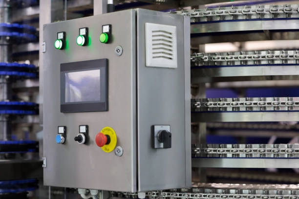
(Istock) Metal enclosure
Selecting a CNC supplier for enclosure machining requires more than checking price or machine count. Enclosure parts introduce specific manufacturing challenges. Thin walls, deep cavities, internal mounting features, and sealing surfaces require precise process control.
A capable supplier should demonstrate consistent machining performance, provide design feedback before production, and maintain dimensional stability across prototype and production runs.
The following criteria help engineers evaluate a supplier’s ability to machine CNC enclosures reliably.
Evaluation Area | What to Look For | Why It Matters for CNC Enclosures |
|---|---|---|
Capability in Thin-Wall and Deep Cavity Machining | Experience machining thin sections without vibration or deformation. Ability to machine deep internal pockets while maintaining surface quality. | Many CNC electronics enclosures include lightweight walls and internal cavities for PCBs or connectors. Shops without proper tooling strategies may struggle with chatter, poor finish, or dimensional drift. |
DFM Feedback and Design Iteration Support | Engineers review CAD models and suggest geometry adjustments before machining begins. Feedback may include tool access improvements, radius changes, or cavity depth recommendations. | Early manufacturability feedback prevents costly redesign after the first prototype. It also helps reduce machining time and setup complexity. |
Consistency from Prototype to Production | Ability to maintain tolerances, surface finish, and machining parameters when moving from one-off prototypes to small batch production. | Enclosure designs often move quickly from testing to low-volume manufacturing. Process stability ensures that production parts match the validated prototype geometry. |
A supplier with strong enclosure machining experience will typically review models early, identify potential machining constraints, and recommend geometry adjustments that simplify production.
Custom CNC Enclosure Machining Services at JLCCNC
Designing a CNC enclosure is not only about geometry—it directly affects cost, manufacturability, and lead time. Early design decisions often determine whether a part is easy or expensive to machine.
JLCCNC produces custom CNC machined enclosures for electronics, automation systems, and industrial equipment. The machining process focuses on maintaining dimensional stability across internal cavities, mounting features, and sealing surfaces.
Upload your enclosure design to JLCCNC for a manufacturability review.
Our engineers will:
- Identify machining risks
- Suggest design improvements
- Optimize for cost and lead time
JLCCNC offers fast turnaround and cost-effective CNC enclosure machining for prototype and low-volume production needs.
FAQ
Q: How thin can walls be in a CNC enclosure?
For small aluminum enclosures, wall thickness often starts around 2–3 mm, but the practical value depends on part size, cavity depth, and machining stability.
Q: What is the best material for CNC enclosures?
Aluminum is most common because it balances machinability, structural strength, and corrosion resistance.
Q: How accurate are CNC machined enclosures?
Typical machining tolerances for enclosure features are around ±0.01–0.05 mm, depending on geometry and material.
Q: Can CNC enclosures be used for low-volume production?
Yes. CNC machining works well for prototype and small batch production because it requires minimal tooling compared with forming processes.
Q: What factors increase CNC enclosure machining cost?
Deep cavities, tight internal radii, multiple setups, and additional finishing processes increase machining time and cost.
Q: When should CNC be used instead of sheet metal for enclosures?
CNC machining becomes preferable when the enclosure requires precise internal features, thick structural walls, or tight alignment tolerances that sheet metal fabrication cannot achieve.
Q: What is a CNC enclosure used for?
A CNC enclosure is used to house and protect internal components such as circuit boards, connectors, sensors, or mechanical parts. It is commonly used in electronics, industrial equipment, medical devices, and custom control systems where fit, rigidity, and surface finish matter.
Q: CNC enclosure vs. sheet metal: what is the difference?
A CNC enclosure is machined from a solid block, which makes it a good choice for tight tolerances, thicker walls, detailed pockets, and a more refined appearance. A sheet metal enclosure is formed from cut and bent metal, so it is usually better for larger sizes, simpler shapes, and higher-volume production at lower cost.
Popular Articles
• CNC Machining in the Medical Industry
• CNC for Luxury Watchmaking: Achieving Sub-Micron Tolerances
• Micro CNC Machining: Techniques for Manufacturing Miniature Components
• CNC Machining vs Sheet Metal: Which is Better for Enclosures?
• Micro CNC Machining Explained: Process, Precision & How Small It Can Really Get
Keep Learning
CNC Machining for Robotics: Custom Robot Parts, Design, and Manufacturing Guide
CNC machining for robotics refers to the use of precision CNC manufacturing to produce critical robotic components such as joints, frames, and motion interfaces. These machined parts for robotics are designed to maintain tight tolerances, structural stability, and repeatable motion under load. In CNC manufacturing robotics, machining quality directly affects positioning accuracy, system stiffness, and long-term performance. (AI generated) CNC machined robot joint components You probably interact with ......
CNC Machining for Electronic Hardware: Design, Tolerances, and Manufacturing Considerations
(AI-generated) CNC milling of an aluminum electronics enclosure CNC machining plays a supporting but critical role in electronics manufacturing. While PCB fabrication creates traces, vias, and plated circuit features, CNC machining is used to produce the structural and mechanical parts that help the final device function reliably. What Is CNC Machining for Electronics CNC machining for electronics is the process of manufacturing high-precision mechanical parts used to support, protect, align, cool, or......
What Is Sheet Metal Ductwork? A Guide to HVAC and Industrial Duct Fabrication
(AI generated) Sheet metal ducts stacked in a factory Sheet metal ductwork is a system of rigid metal air channels used to distribute airflow in HVAC and industrial ventilation systems. It is commonly fabricated from galvanized steel and designed to minimize air leakage, pressure loss, and energy consumption. Go into any factory, hospital, or data center and look up. Behind the ceiling panels sits a metal network moving thousands of cubic meters of air every hour. Most people will never notice it or t......
Sheet Metal Roofing: Types, Panels, Systems & Practical Guide
What is Sheet Metal Roofing (AI generated)Metal sheet roofing Sheet metal roofing is a roofing system made from thin, formed metal sheets—typically steel, aluminum, or copper—designed to protect buildings from weather while providing durability, corrosion resistance, and long service life. It is widely used in residential, commercial, and industrial buildings due to its strength, lightweight properties, and low maintenance requirements. Most roof failures don’t happen because of the metal itself; it’s......
HVAC Sheet Metal Fabrication: Ductwork Techniques, Standards, and Best Practices
(AI generated) Worker shaping metal sheet on press brake HVAC Sheet Metal Fabrication: Key Types and When to Use Overview of Common HVAC Sheet Metal Materials HVAC sheet metal fabrication is the foundation of modern HVAC ductwork systems. From standard HVAC duct fabrication to custom HVAC sheet metal fabrication, precision in material selection and processing directly impacts airflow efficiency, leakage control, and system longevity. In HVAC sheet metal fabrication, material selection directly influen......
CNC Enclosure Design for Machining: Cost, Materials, and Production Considerations
What Is a CNC Machined Enclosure (AI generated) CNC-machined aluminum enclosure with internal cavities A CNC machined enclosure is a housing manufactured by removing material from a solid block using milling or turning operations. The process creates accurate internal cavities, threaded features, and sealing surfaces. Engineers use CNC machining when the enclosure must hold electronics, sensors, or mechanical assemblies with tight alignment requirements. Typical examples include control modules, instr......