Custom Keyboard Case: Design, Materials, and Machining
21 min
- What Is a Custom Keyboard Case?
- How to Design a Custom Keyboard Case
- Materials for Custom Keyboard Cases
- CNC Machining Considerations for Custom Keyboard Cases
- What Affects the Cost of a Custom CNC Keyboard Case?
- Surface Finishing for Custom Keyboard Cases
- Common Custom Keyboard Case Design and Manufacturing Issues
- Custom Keyboard Case FAQs
Key Takeaways
- Start with the PCB and plate, not the outside shape of the case.
- 60%, 65%, 75%, and TKL layouts can have very different PCB, plate, mounting, and internal-clearance requirements.
- 6061-T6 is a practical starting point for CNC keyboard cases because it offers good machinability, wide material availability, adequate mechanical performance, and a broad range of surface-finishing options.
- Brass can produce a much heavier, denser case with a different acoustic and tactile character.
- Thin walls and deep internal cavities are among the biggest manufacturing challenges in a custom mechanical keyboard case.
- Anodizing isn't dimensionally neutral. A coating changes the final size of machined surfaces, so critical fits need to be considered before finishing.
- A production-ready CAD model should define the PCB, plate, mounting points, screw holes, clearances, cavity depths, and finish requirements, not just the outside silhouette.
A keyboard case is easy to underestimate. From the outside, it looks like a simple shell with a few screw holes. In reality, the case has to locate a PCB, support a plate, clear switches and stabilizers, accommodate the chosen mounting system, survive repeated assembly, and still look good after machining and finishing.
CNC machining makes the design constraints more significant, especially when the case is produced from aluminum billet or plate stock. The geometry, material, tooling, tolerances, mounting strategy, and surface finish all have to work together.
For anyone developing a custom mechanical keyboard, the best time to solve those problems is before the first block of aluminum reaches the CNC machine.
The case affects keyboard mass, structural stiffness, acoustic behavior, mounting behavior, and assembly. Its influence on typing feel depends largely on how the case interacts with the plate, PCB, and mounting system. A multi-kilogram aluminum case behaves very differently from a lightweight plastic enclosure. A gasket-mounted plate behaves differently from one screwed directly to the case. A deep cavity that looks fine in CAD can become expensive if the required cutter cannot reach its bottom corners.
The process starts with the electronics and mechanical interfaces, then moves outward into the case geometry. Once those constraints are locked down, material, machining strategy, finishing, and inspection can be selected around them.
What Is a Custom Keyboard Case?
A custom keyboard case is a purpose-designed enclosure built around a specific PCB, plate, switch layout, mounting system, and set of internal components rather than a generic keyboard standard. It can be machined, printed, molded, or fabricated from several materials, but the geometry is designed around the intended keyboard architecture.
An off-the-shelf case normally follows an established form factor and mounting pattern. A custom case gives the designer control over the exterior dimensions, internal cavity, mounting structure, materials, weight, finishing, and visual details.
For a custom mechanical keyboard, that means the case becomes part of the product's engineering rather than simply a container around the electronics.
How to Design a Custom Keyboard Case
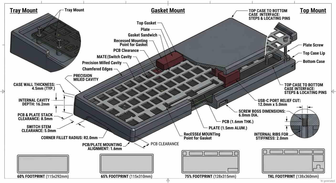
Custom mechanical keyboard case design
The right way to design a custom keyboard case is to work from the interfaces outward.
Start with the PCB and plate. Then define how those components are supported. After that, establish internal clearances, cavity dimensions, wall thicknesses, screw locations, and external geometry.
This order matters because changing the PCB interface late in the process can force changes throughout the entire case.
1. PCB and Plate Compatibility
The PCB is the first reference geometry.
Before drawing the case, obtain the actual PCB dimensions, mounting-hole coordinates, USB connector location, daughterboard position if applicable, and any components that extend below or above the board.
The same applies to the plate. A plate isn't just a rectangle containing switch cutouts. Its outer profile, screw locations, mounting tabs, flex zones, and relationship to the PCB all affect the case.
Layout names are useful starting points, but they aren't sufficient manufacturing information. A 60% layout typically omits the number pad, dedicated function row, and dedicated navigation cluster, while many 65% layouts retain arrow keys and some navigation keys in a more compact footprint. A 75% layout generally retains the function row in a condensed arrangement, while a TKL layout keeps the function and navigation areas but removes the number pad. Exact key arrangements vary by PCB and plate design, so the actual component files should take priority over the layout name.
Even within the same layout, PCB mounting holes and outer dimensions can differ.
Standard ANSI layouts commonly use a 6.25u spacebar, while alternatives such as Tsangan and HHKB use different bottom-row arrangements. That matters because the plate and PCB have to agree on the exact key geometry rather than merely the marketing name of the layout.
For a production custom mechanical keyboard, always design around the actual PCB and plate files.
2. Mounting Features and Internal Clearances
Once the PCB and plate are fixed, determine how they will sit inside the enclosure.
Define:
- PCB support points
- Screw-hole locations
- Standoff height
- Plate position
- USB connector clearance
- Daughterboard clearance
- Battery or controller clearance where applicable
- Screw-head clearance
- Cable routing
- Bottom cavity clearance
Don't leave these as approximate spaces.
For example, if a USB-C connector extends 2 mm beyond the PCB edge, the case wall needs enough clearance for the connector housing, cable plug, and manufacturing tolerance. The same applies to screws. A hole that technically accepts an M2 screw may still be unusable if the driver cannot reach it.
The internal geometry should also account for assembly. A component that fits perfectly in a static CAD model can become impossible to install when another component blocks the required insertion path.
3. Mounting Styles: Tray, Gasket, and Top Mount
The mounting system changes the internal structure considerably.
Tray mount is comparatively simple. The PCB or plate assembly is supported by standoffs attached directly to the lower case.
Top mount attaches the plate to mounting points around the upper case. This keeps the mounting structure relatively direct and can produce a firm typing feel.
Gasket mount introduces compliant material between the plate and case. The gasket locations, compression, pocket dimensions, and plate movement all need to be considered in the CAD model.
Don't design the outer shell first and try to squeeze the mounting system into whatever space remains. The mounting architecture should be established before the outside profile is finalized.
4. Case Walls, Cavities, and Tool Access
At this stage, the enclosure geometry becomes directly constrained by CNC tool access, workholding, and cutting stability.
The internal cavity needs enough room for the PCB, plate, mounting hardware, and any components below the board. But making the cavity deeper or narrower can make it harder to machine.
Standard cylindrical end mills leave a radius in internal vertical corners rather than producing a true sharp corner. The cutter also needs sufficient physical access to the feature being machined.
If a cavity is 20 mm deep but only 8 mm wide, a long slender tool may be required. That increases tool deflection and vibration risk compared with a shorter, more rigid cutter.
For that reason, don't judge manufacturability purely from the rendered CAD model. Look at the model from the cutter's point of view.
Wall thickness matters too. Very thin aluminum walls can move under cutting forces or distort as material is removed from one side. A symmetric machining strategy and adequate wall thickness make the case easier to hold dimensionally.
5. Internal Corner Radii and Small Features
CNC milling naturally produces radiused internal corners.
If a cavity is designed with a 90-degree internal corner, the cutter has to leave a radius unless a specialized tool or secondary operation is used.
For example, a 3 mm diameter end mill will generally produce an internal corner radius of about 1.5 mm, assuming the corner is machined with that tool.
Designing realistic corner radii early avoids unnecessary machining operations.
Small decorative pockets can create the same problem. A tiny slot may require a small-diameter cutter, while a deep slot with a small radius can create a poor length-to-diameter ratio for the tool.
The practical rule is simple: use larger radii and larger tools wherever the design allows it.
6. Preparing a Production-Ready CAD File
A production CAD package should make the manufacturing intent obvious.
Include:
- Final overall dimensions
- PCB and plate reference geometry
- Mounting-hole coordinates
- Thread specifications
- Critical clearances
- Cavity depths
- Wall thicknesses
- Corner radii
- Surface-finish requirements
- Material specification
- Anodizing or other finishing requirements
- Critical dimensional tolerances
STEP is a useful neutral format for transferring mechanical geometry to a CNC manufacturer, but the 3D model alone does not define every manufacturing requirement. Critical dimensions, tolerances, material, surface finish, and other inspection requirements should also be provided in a drawing or equivalent manufacturing documentation. STL is primarily a mesh format and is generally less suitable for precision mechanical manufacturing.
Before sending the model, perform an assembly check. Put the PCB, plate, switches, stabilizers, screws, daughterboard, and other relevant components into the CAD assembly and verify that nothing intersects.
Here's a detailed guide on how to prepare your CAD file for CNC machining.
Once the PCB, plate, mounting system, and case geometry are ready, you can send the production CAD file for manufacturability review and pricing.

Precision CNC Machining Service
Upload your keyboard case CAD file to JLCCNC for a CNC machining quote.
Materials for Custom Keyboard Cases
Material changes more than the appearance of a case.
It affects weight, stiffness, machining behavior, thermal characteristics, surface texture, finishing options, and the way the enclosure interacts acoustically with the plate and PCB.
For a custom mechanical keyboard, those differences are noticeable because the case is a relatively large structural component surrounding a small set of moving parts.
6061 aluminum has a density of about 2.70 g/cm3, while common brass is around 8.5 g/cm3. A solid brass component can therefore weigh roughly three times as much as an equivalent aluminum volume before accounting for differences in geometry.
Aluminum for CNC Keyboard Cases
6061-T6 is usually the sensible starting point for a CNC aluminum keyboard case.
It machines cleanly, is widely available, has a useful strength-to-weight ratio, and can be anodized in a broad range of colors. Its density is only about one-third that of steel, which lets a designer create a substantial enclosure without making it excessively heavy.
For many projects, 6061-T6 is a better starting point than immediately jumping to a harder alloy.
7075 provides higher strength than 6061, but for many keyboard enclosures, strength is not the primary design constraint. The case is more likely to be constrained by wall thickness, machining access, appearance, mounting geometry, or cost.
Aluminum also gives designers considerable freedom with finishing. A machined surface can be bead blasted, brushed, polished, or anodized depending on the desired appearance.
Brass and Other Metal Options
Brass changes the equation dramatically.
At roughly 8.5 g/cm3, brass is more than three times as dense as 6061 aluminum. That extra mass is one reason brass cases and weights are popular in enthusiast keyboard designs.
The acoustic result is also different, although it isn't determined by material alone. Plate material, mounting system, cavity geometry, internal dampening, PCB construction, switch type, keycaps, and the physical structure of the case all contribute to the final sound.
Brass can also be used selectively rather than for the entire enclosure. A designer might use an aluminum upper case with a brass internal weight, for example, gaining additional mass without machining the entire enclosure from a much denser material.
Stainless steel is another option when higher stiffness, wear resistance, corrosion resistance, or a specific appearance is required, although it is substantially more demanding to machine than aluminum.
Plastic Materials for Keyboard Cases
Plastic remains useful when low weight, lower material cost, electrical isolation, or a different acoustic response is more important than the mass and appearance of machined metal.
POM, nylon, and other engineering plastics can be CNC machined into cases, although their behavior differs from aluminum. Plastics generally have lower stiffness and greater thermal expansion, and their surfaces don't respond to finishing processes in the same way as aluminum.
| Density, approx. | Machinability | Weight | Typical Finish | General Character | |
|---|---|---|---|---|---|
| 6061-T6 aluminum | 2.70 g/cm3 | Excellent | Light-medium | Anodize, bead blast, brush, polish | Balanced, versatile |
| 7075 aluminum | 2.81 g/cm3 | Very good | Light-medium | Anodize, blast, brush | Higher-strength option |
| Brass | 8.4-8.7 g/cm3 | Good | Very heavy | Polish, brush, plate, patina | Dense, substantial |
| Stainless steel | ~8.0 g/cm3 | Moderate-difficult | Very heavy | Bead blast, polish, brush | Rigid, premium |
| POM/Delrin | ~1.4 g/cm3 | Excellent | Very light | Machined finish | Low-friction polymer |
| Nylon | ~1.1-1.2 g/cm3 | Good | Very light | Machined surface | Tough, lightweight |
CNC Machining Considerations for Custom Keyboard Cases
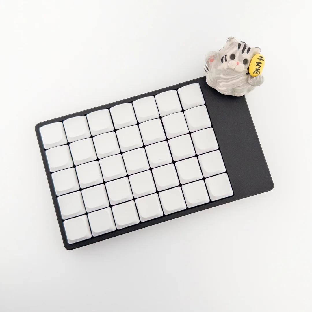
CNC aluminum keyboard case
CNC machining a keyboard enclosure is mostly an exercise in removing material while keeping the remaining structure stable.
The machine first establishes the external profile and major pockets. Deeper internal cavities and smaller features are then machined using appropriate tools. Mounting holes, threads, connector openings, and other critical features are produced according to the drawing or CAD specification.
A CNC keyboard case may look simple from the outside, but most of the machining work can happen inside the part.
CNC Milling the Case and Internal Cavities
Depending on the geometry and workholding strategy, a CNC-machined keyboard case may involve:
- Facing the stock and establishing reference surfaces
- Roughing major pockets and external features
- Semi-finishing and finishing cavity walls and floors
- Machining bosses, mounting features, and connector openings
- Drilling and tapping holes
- Finishing visible external surfaces
- Repositioning the part for a second setup when required
- Deburring and preparing the part for surface finishing
The exact sequence should be selected to maintain workholding stability, tool access, dimensional control, and surface quality.
Machining Thin Walls and Deep Cavities
Thin walls are one of the easiest ways to turn a straightforward enclosure into a difficult machining job.
A long cutter can deflect. A thin wall can vibrate. Removing material asymmetrically can release internal stress and allow the part to move.
Deep cavities create another problem: tool reach.
A cutter needs enough clearance to reach the cavity floor without the tool holder or spindle nose colliding with the surrounding wall. The longer the tool becomes relative to its diameter, the more sensitive the operation becomes to deflection and vibration.
A case designed with a slightly wider cavity and larger internal radius can sometimes be substantially cheaper to machine than one that is only marginally smaller.
Tolerances for PCB and Mating Features
Not every dimension on a keyboard case needs the same tolerance.
A cosmetic outside dimension generally doesn't need the same control as a PCB locating feature.
Reserve tighter tolerances for features such as:
- PCB locating pockets
- Plate locating features
- Alignment pins
- Connector openings
- Thread locations
- Mating surfaces
- Critical case-to-case interfaces
Don't automatically specify plus or minus 0.01 mm everywhere.
Tighter tolerances require more careful machining, measurement, temperature control, and potentially additional finishing operations. If a feature functions perfectly at plus or minus 0.05 mm, specifying plus or minus 0.01 mm only adds manufacturing burden.
This is one of the most important principles in how to make a custom keyboard case efficiently: tolerance should follow function.
Inspection of Critical Dimensions
Inspection should focus on the features that determine whether the keyboard actually fits together.
Inspection methods should match the feature being controlled. Calipers may be sufficient for non-critical external dimensions, while critical locations, profiles, and feature relationships may require a CMM. Holes can be checked with pin gauges or bore gauges, and external dimensions can be verified with micrometers or other appropriate instruments.
For a precision case, the inspection plan should identify the dimensions that matter before machining begins.
That is especially important when the case will be anodized afterward. The machined dimension isn't necessarily the final dimension.
What Affects the Cost of a Custom CNC Keyboard Case?
The cost of a custom CNC keyboard case depends primarily on material usage, machining time, setup requirements, part tolerances, finishing, and order quantity. The geometry of the case often has a greater effect on cost than its overall size.
Cost can often be reduced during the design stage. Choosing stock closer to the finished envelope, allowing practical internal radii, avoiding unnecessary tight tolerances, and keeping functional features accessible from fewer setups can reduce machining time without changing the intended function of the case.
| Cost Impact | |
|---|---|
| Material volume | Larger billets increase material cost and may require more stock removal. |
| Machining time | Deep pockets, complex contours, and extensive finishing increase cycle time. |
| Number of setups | Additional orientations add workholding and alignment operations. |
| Tool requirements | Small cutters or long tool reach can increase machining time. |
| Tolerances | Tighter functional tolerances can require closer process control and inspection. |
| Surface finishing | Anodizing, blasting, brushing, polishing, and masking add secondary processing. |
| Order quantity | Setup and programming costs have a greater effect on unit price at low quantities. |
Precision CNC Machining Service
Have a production-ready keyboard case design? Upload the CAD file to JLCCNC for a project-specific CNC machining quote and DFM review.
Surface Finishing for Custom Keyboard Cases
Finishing is part of the engineering specification, not merely a cosmetic step.
A machined aluminum surface can look excellent straight off the CNC machine, but anodizing, blasting, brushing, and polishing produce very different results.
Anodizing Aluminum Keyboard Cases
Anodizing is one of the most common finishes for a CNC aluminum keyboard case because it creates a durable oxide layer rather than simply applying paint to the surface.
Type II anodizing is widely used for decorative aluminum parts, while Type III hardcoat provides a thicker, harder coating for applications where wear resistance matters.
The important detail for precision parts is that anodizing changes dimensions.
Anodizing converts part of the aluminum surface into oxide and also grows material outward. For Type III hardcoat, a 50/50 split is a useful engineering approximation, although the actual buildup-to-penetration ratio depends on the alloy and anodizing process. As a practical example, a 0.002-inch coating may produce roughly 0.0009-0.001 inch of outward buildup per coated surface. Critical holes, pockets, threads, and mating surfaces should be reviewed for coating allowance and specified according to their finished condition.
That matters for tight pockets, holes, threaded interfaces, and other mating surfaces.
A bore that is perfect before anodizing may be too small afterward if the coating allowance wasn't considered.
Bead Blasting, Brushing, and Polishing
Bead blasting produces a uniform matte texture and helps hide small machining marks. It's a common choice for a clean, understated enclosure.
Brushing creates directional grain. It's particularly useful when the design calls for a more traditional machined-metal appearance.
Polishing produces a brighter surface but makes scratches, handling marks, and surface imperfections more visible.
The choice often comes down to the intended product rather than machining capability.
A black anodized and blasted enclosure looks completely different from a clear-anodized, brushed one even when both start from the same 6061 stock.
How Surface Finishing Affects Mating Features
Critical mating surfaces should be identified before finishing.
If an internal pocket needs a specific final dimension, the machinist and finishing supplier need to know that the dimension applies after anodizing, not merely before it.
Masking can also be used where a surface must remain free of anodizing. This can be useful for electrical contact surfaces or tight dimensional interfaces. Masking can also be used to keep selected areas free of anodizing where electrical contact, grounding, or dimensional requirements make an uncoated surface necessary.
The important thing is to define the finished condition on the drawing rather than assuming the finishing process is dimensionally invisible.
Common Custom Keyboard Case Design and Manufacturing Issues
PCB and Mounting Feature Misalignment
This is usually a data problem rather than a CNC problem.
If the PCB mounting coordinates are wrong in CAD, the machine can produce the wrong holes perfectly.
Always use the actual PCB drawing or CAD model. Don't measure mounting-hole positions from a screenshot or image.
The same applies to daughterboards and connector locations. A few tenths of a millimeter can matter when several mounting features have to align simultaneously.
Distortion in Thin-Walled Sections
A thin wall can deflect during machining even if the final CAD geometry looks rigid.
The problem becomes more severe when the wall is tall, unsupported, or separated from a large cavity.
Machining strategy matters here. Roughing and finishing should be planned so that the wall isn't suddenly left carrying cutting forces it wasn't designed to withstand.
Interference Between Mating Components
An enclosure can pass a basic CAD check and still fail assembly because of tolerance stack-up.
Consider the PCB, plate, screws, standoffs, switches, daughterboard, and case together.
Each component has its own manufacturing variation. The important question isn't whether the nominal models fit; it's whether the worst reasonable combination of dimensions still assembles.
Dimensional Variation After Surface Finishing
Finishing can change the final dimensions.
This is particularly relevant for anodized aluminum. The coating thickness, alloy, anodizing process, masking, and pretreatment all influence the final result.
For a decorative exterior surface, a small dimensional change may not matter. For a precision pocket or mating interface, it can be the difference between a clean fit and a part that needs rework.
Precision CNC Machining Service
Professional manufacturing, fast turnaround, and quality assurance.
Custom Keyboard Case FAQs
Q: What Is a Custom Mechanical Keyboard Case?
A custom mechanical keyboard case is an enclosure designed around a particular mechanical keyboard PCB, plate, mounting system, and component arrangement. Unlike a generic replacement shell, it can be engineered around a specific layout, material, cavity geometry, mounting method, and exterior design.
Q: What Material Is Best for a Custom Keyboard Case?
For most CNC-machined projects, 6061-T6 aluminum is the practical starting point. It combines approximately 2.70 g/cm3 density with good machinability and a wide range of finishing options.
Brass is a better choice when substantial weight and a different acoustic character are priorities. Plastics make more sense when low weight, electrical isolation, or a different feel is the goal.
Q: Can You CNC Machine an Aluminum Keyboard Case?
Yes. An aluminum enclosure is a common CNC-machining application. A CNC aluminum keyboard case can be milled from 6061-T6, 7075, and other aluminum alloys, then bead blasted, brushed, polished, or anodized.
The main design constraints are cavity depth, tool access, internal radii, wall thickness, workholding, and the tolerances required on PCB and mounting features.
Q: What CAD Files Are Needed for a Custom Keyboard Case?
At minimum, provide a production-ready STEP model of the case plus the PCB and plate geometry or accurate drawings showing their dimensions and mounting locations.
For a custom mechanical keyboard case, it's also useful to provide the PCB revision, plate material and thickness, mounting style, screw specifications, desired material, surface finish, and any critical dimensional requirements.
Q: What Mounting Styles Can Be Machined?
Tray mount, top mount, gasket mount, and other custom mounting arrangements can be incorporated into a CNC enclosure.
The important point is to design the mounting architecture before finalizing the case cavity. Gasket pockets, plate supports, standoffs, screw locations, and compression clearances all need to be represented in the CAD model.
Conclusion About Custom Keyboard Case
A well-designed custom keyboard case starts with the PCB and plate and works outward from there.
The most important decisions aren't the decorative ones. They are the mounting architecture, internal clearances, cavity dimensions, wall thickness, tool access, material, tolerances, and final surface treatment.
6061-T6 aluminum remains an excellent general-purpose choice for CNC machining because it combines low density, good machinability, strength, and finishing flexibility. Brass makes sense when mass is part of the design. Engineering plastics provide another route when weight and material behavior matter more than the appearance of machined metal.
The machining process should be considered while the case is still being designed. A cavity that is easy to draw isn't necessarily easy to mill. A 0.01 mm tolerance isn't automatically better than a 0.05 mm tolerance. And a perfectly machined dimension can become incorrect after finishing if coating buildup wasn't considered.
A production-ready custom keyboard case is designed around its interfaces first, then optimized for the material, machining process, tolerances, workholding, and finishing requirements that those interfaces create. The result is a case that is not only visually correct in CAD but also manufacturable, inspectable, and reliable in assembly.
Popular Articles
• How CNC Customization Can Strengthen Client Relationships During the Christmas Season
• Creating Unique New Year's Day Gifts with CNC Technology
• Valentine's Day Gifts and CNC Machining: Creating Unique Love
• Easter Creative Gifts: CNC Machining Helps Revitalise Traditional Gifts
• Customised Gifts for Mother's Day CNC Machining to Create Unique Thoughts
Keep Learning
Custom Keyboard Case: Design, Materials, and Machining
Key Takeaways Start with the PCB and plate, not the outside shape of the case. 60%, 65%, 75%, and TKL layouts can have very different PCB, plate, mounting, and internal-clearance requirements. 6061-T6 is a practical starting point for CNC keyboard cases because it offers good machinability, wide material availability, adequate mechanical performance, and a broad range of surface-finishing options. Brass can produce a much heavier, denser case with a different acoustic and tactile character. Thin walls......
Customised Gifts for Mother's Day CNC Machining to Create Unique Thoughts
On Mother's Day every year, people pick gifts for their mothers to express their deep love and appreciation. However, in this fast-paced era, it is often difficult for traditional gifts to stand out and truly impress mothers. In order to make their mothers feel unique and cared for, more and more people are choosing customised gifts, and CNC machining technology is the perfect tool to achieve this goal. I. Why choose CNC machining to make Mother's Day gifts? 1. High Precision and Complex Designs CNC m......
Easter Creative Gifts: CNC Machining Helps Revitalise Traditional Gifts
I. Introduction Easter, as one of the most important festivals around the world, not only carries religious and cultural significance, but also is a time for family and friends to give each other gifts and express their blessings. With the growing consumer demand for personalisation and creativity, traditional Easter gifts are gradually developing in the direction of customisation and innovation. And in this process, CNC machining technology, as an important tool in modern manufacturing, is playing an......
Creating Unique New Year's Day Gifts with CNC Technology
New Year's Day, as the beginning of the New Year, is a time to share your blessings and joy with your friends and family. A well-chosen or handmade gift can express your most sincere feelings. With the development of CNC (Computer Numerical Control) technology, the choices of personalized and creative gifts become more diversified. In this article, we will discuss how to utilize CNC technology to create special New Year's Day gifts that will make your gift stand out from the crowd. Personalized New Ye......
Christmas 2024: Creating a unique CNC-machined Christmas gift
The holiday season is all about finding that special gift, something thoughtful and unique that shows you’ve put in the effort. If you're someone who enjoys precision and craftsmanship, CNC machining could be the perfect way to create custom Christmas presents that stand out. Whether you're looking to make a personalized keychain, a functional piece of art, or something entirely unique, CNC machines offer the tools to bring those ideas to life. Why CNC Machined Gifts? When it comes to holiday gift-giv......
Valentine's Day Gifts and CNC Machining: Creating Unique Love
On Valentine's Day, a day full of love, people are looking for special ways to express their emotions. Among the many gifts, personalized and customized gifts stand out because of their uniqueness. With the rapid development of technology, CNC machining technology has become a key tool to realize the dream of personalized gifts. This article will show you how to use CNC machining technology to add a special meaning to your Valentine's Day gifts. CNC Machining Technology CNC machining technology has re......