Lathe vs Mill: Differences, Applications, and Machine Selection
17 min
- What Is the Difference Between a Lathe and a Mill?
- Which Parts Are Best Suited to a Lathe or a Mill?
- How Do Feature Access and Setup Affect Lathe vs Mill Selection?
- What Machine Limits Can Affect Lathe vs Mill Selection?
- When Should Turning and Milling Be Combined?
- Lathe vs Mill FAQs
- Conclusion About Mill and Lathe
Key Takeaways
- Lathe-vs-mill selection starts with the part, not the machine: a lathe is the more direct route for rotational features, while a mill suits prismatic geometry and features distributed across multiple faces.
- On a lathe the workpiece spins and the tool feeds; on a mill the cutting tool spins while the workpiece is held. That motion difference determines the geometry each machine produces efficiently.
- Workholding, feature access, setup count, and cross-feature tolerance relationships decide whether one machine is enough or a combined process is more practical.
- Mixed parts can be made through separate turning and milling operations, a lathe with live tooling, or a mill-turn platform.
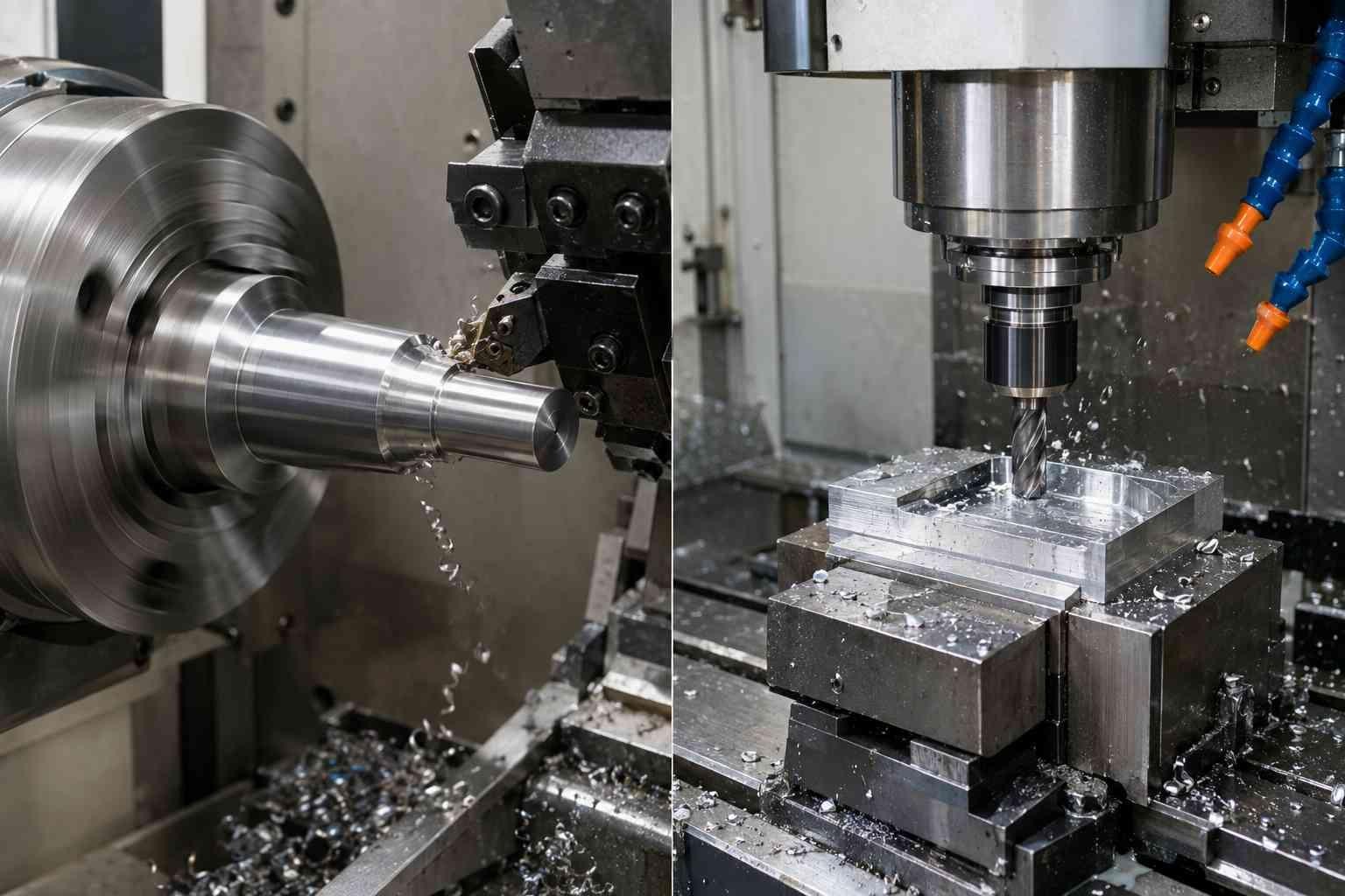
CNC lathe and CNC milling machine
Lathe-vs-mill selection starts with the part, not the machine. A lathe is typically the more direct route for rotational features, while a mill is better suited to prismatic geometry and features distributed across multiple faces. From there, workholding, feature access, tolerance relationships, stock form, and setup count determine whether one machine is enough or a combined process is more practical.
This is not a general accuracy contest. A shaft dominated by controlled OD and ID features will usually favor turning, while a part whose critical features are pockets, hole patterns, or multiple machined faces will usually favor milling. The drawing and the relationships between those features determine the process.
What Is the Difference Between a Lathe and a Mill?
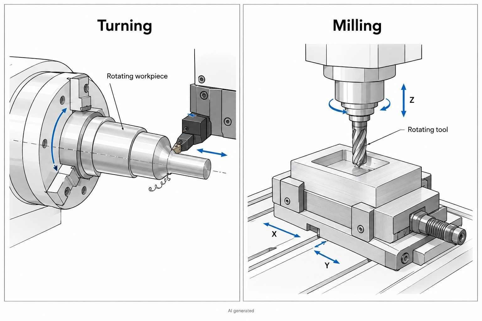
Standard CNC turning and standard 3-axis CNC milling
The main difference here is what moves. On a lathe, the workpiece spins. On a mill, the cutting tool spins. For a more detailed comparison of the two CNC processes, see our guide to CNC milling vs. CNC turning
The distinction is simple, but it affects the geometry each machine produces efficiently, how the part is held, which feature relationships are easier to control, and how much setup work is required.
A conventional CNC lathe rotates the workpiece while the cutting tool feeds relative to the spindle centerline, typically along X and Z. The spindle rotation creates the rotational surface, while controlled tool motion determines diameter, length, shoulders, grooves, tapers, and threads. Because the workpiece spins, every surface the tool touches is generated by that rotation. This is why lathes produce cylindrical, conical, and spherical geometry. The rotation is the feature. A turned diameter is round because the part was spinning uniformly during the cut, not because the machine traced a circle.
A standard 3-axis mill holds the workpiece in a fixture while the spindle rotates the cutting tool and the machine positions it along X, Y, and Z. On 4- and 5-axis equipment, rotary motion can also change the tool or workpiece orientation, allowing features to be reached from additional directions without fully re-fixturing the part. Flat surfaces, pockets, slots, contours, drilled hole patterns- all of it comes from the tool path, not from any rotation of the part itself.
As a first-pass rule, rotationally symmetric parts usually favor a lathe, while predominantly prismatic parts usually favor a mill. The decision can change when the part has secondary features, difficult workholding, tight cross-feature relationships, or access requirements that favor a different setup.
| Factor | Lathe | Mill |
|---|---|---|
| Primary motion | Workpiece rotates; cutting tool feeds along programmed axes | Cutting tool rotates; workpiece is clamped while machine axes position the tool relative to it |
| Geometry produced | Cylindrical and rotational profiles, including shoulders, grooves, tapers, and threads | Flat faces, pockets, slots, hole patterns, contours, and multi-face features |
| Typical parts | Shafts, bushings, pistons, pins | Brackets, housings, plates, complex prismatic parts |
| Axis count (standard) | 2-axis (X and Z) turning | 3-axis (X, Y, Z) milling |
| Tolerances | Strong on turned diameters and rotational feature relationships | Strong on feature location, pockets, planar features, and multi-face relationships |
| Part holding | Chuck, collet, between centers | Vise, fixture, T-slot table |
| Combined capability | Mill-turn with live tooling | 4/5-axis with rotary table |
Not sure whether the part is better suited to turning, milling, or both? Upload the CAD file and drawing to JLCCNC for an engineering review of the geometry and required feature access before the machining route is quoted.

Precision CNC Machining Service
Professional manufacturing, fast turnaround, and quality assurance.
Which Parts Are Best Suited to a Lathe or a Mill?
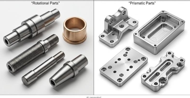
CNC lathe rotational parts compared with CNC mill prismatic parts
Rotational and Cylindrical Parts
Shafts, axles, spindles, pistons, bushings, sleeves, pins, arbors, threaded rods, pulleys, rollers, the lathe is the natural home for anything whose primary geometry is defined by rotation around an axis. These parts favor turning because their primary features share the spindle axis. When multiple diameters, shoulders, or bores are machined in the same setup, their relationships can be controlled from a common rotational reference rather than transferred between separate setups. For a deeper look at turning operations, machine behavior, materials, and typical applications, see our CNC turning guide
A 5 μm diameter tolerance may be achievable on selected features under controlled conditions, but actual results depend on machine condition, thermal stability, tool wear, workholding, material behavior, and the inspection method. Turning has a direct kinematic relationship to the spindle axis, but the final dimension still depends on the complete machining process.
Common turning operations include external and internal threading, grooving, boring, facing, and tapering. They are especially efficient when the feature is coaxial with the spindle, while live-tooling and mill-turn platforms extend a turning center into non-round milling and drilling operations.
Prismatic and Multi-Face Parts
A bracket dominated by bolt holes, pockets, and flat mating surfaces is generally better suited to milling because its critical geometry is not organized around a single axis of rotation. A mill is the right machine, the part sits in a vise, and the tool works across its faces to produce slots, pockets, holes, and counterbores.
The mill's three-axis motion handles prismatic geometry naturally. Flat surfaces come from face milling or fly-cutting. Pockets come from end milling. Hole patterns come from drilling cycles. Contoured profiles in XY come from contouring operations. These features are generally outside the capability of a conventional 2-axis lathe, although a turning center with live tooling, C-axis, or Y-axis capability can machine many of them without transferring the part to a separate mill.
Each of these operations behaves differently under cutting load and tool engagement. Our guide to CNC milling operations breaks down the main milling methods and how the operation affects machining results.
As the part requires more angled or multi-face features, a 3-axis mill may require additional fixturing or repositioning, while 4- or 5-axis machining can provide the required tool access with fewer setups. But the fundamental point remains: flat, positional, and predominantly prismatic geometry is generally most naturally produced on a mill.
How Do Feature Access and Setup Affect Lathe vs Mill Selection?
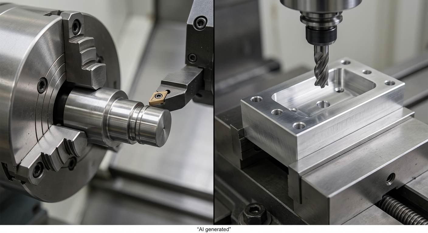
CNC lathe chuck and milling vise showing different workholding methods
Workholding and Part Orientation
How a part gets held changes almost everything about the machining process. On a lathe, cylindrical parts get gripped in a 3-jaw chuck, collet, or 4-jaw chuck for the majority of work. The workholding is concentric by design, the chuck centers the part on the machine's axis of rotation, which is exactly what's needed. Long parts get supported between centers or with a tailstock. Lathe workholding establishes the part around the spindle axis, but actual runout and coaxiality still depend on chuck or collet condition, jaw contact, part geometry, and clamping.
Mills use vises, step clamps, angle plates, sine plates, custom fixtures, and vacuum tables depending on the part. The flexibility is greater than a lathe but so is the setup complexity. A part needs to be located against a datum, clamped without distortion, and oriented so the features being machined are accessible from the spindle. For a simple prismatic part in a vise, this is straightforward. For a complex part needing features on five faces, workholding strategy becomes a serious design and planning problem.
The number of setups required to complete a part directly affects cost and feature-to-feature accuracy. Each additional setup adds setup time and creates another opportunity for positioning error because the part coordinate system must be re-established. A well-planned workholding strategy can reduce unnecessary re-fixturing and make critical feature relationships easier to maintain.
Tool Access and Machine Axes
A standard lathe operates in X and Z, radially toward the spindle axis and along it. The tool can only reach features accessible from the outside diameter or the ends of the part. Internal features (bores, internal threads, recesses) are cut with boring bars and internal tooling inserted along the Z axis from one end. On a conventional 2-axis turning setup, side milling, off-axis cross-holes, flats, and keyways generally require a secondary operation. A turning center with C-axis and live tooling can perform many of these features without removing the part.
A standard 3-axis mill moves in X, Y, and Z. The spindle points straight down (on a vertical mill) or horizontally (on a horizontal mill). Features on the top of the part are naturally accessible. Features on the sides require repositioning the part, and features at compound angles require either angle plates, additional setups, or 4/5-axis capability.
This access question is the practical starting point when deciding between lathe and mill. Can the features be reached from the available axes in a reasonable number of setups? Difficult feature access increases setup complexity and can make tolerance control more demanding.
Datums and Setup Strategy
Setup strategy for a lathe typically centers around the rotational axis, chuck the part, face the end to establish the Z datum, and turn from there. For turned parts, the spindle centerline often serves as the manufacturing reference for coaxial features, but it should not be confused with a drawing datum. The drawing's datum reference frame defines the design intent, while the machining setup determines how that intent is established and maintained during production.
Mill setup strategy requires deliberate datum selection. Which surface will be the Z reference? Which face establishes X and Y? Which features are critical and should be machined in the same setup to maintain accuracy? The answer drives how the part gets held, in what order the setups run, and which features get their tight tolerance callouts in which orientation. Getting this planning right before cutting starts separates well-executed machining from jobs that end up with features that are individually correct but incorrectly related to each other.
What Machine Limits Can Affect Lathe vs Mill Selection?
Tolerance and Dimensional Control
Lathes can hold tight tolerances on diameters and turned lengths, but the achievable tolerance depends on the machine, part geometry, material, workholding, tooling, thermal conditions, and inspection method. Tight tolerances in the ±0.005–0.010 mm range may be achievable on selected features under tightly controlled conditions, but they should not be treated as a universal or routine capability. Coaxial relationships between turned features can be easier to control when those features are machined in the same setup, because they are generated from the same spindle axis.
Milling can hold tight dimensional and positional tolerances, but the achievable result depends on feature size, tool reach, workholding rigidity, material, thermal condition, and finishing strategy. A numerical tolerance should therefore be treated as feature-specific rather than as a universal capability of the mill. A milled circular pocket can be highly accurate, but its size and roundness depend on cutter geometry, tool deflection, machine calibration, interpolation accuracy, and the finishing strategy. A turned bore is generated directly from the spindle axis, which can simplify control of diameter, roundness, and coaxial relationships when the relevant features are machined in the same setup.
The key question is which tolerances are specified and which features carry them. If the critical relationship is between coaxial diameters or bores on a rotational part, turning may offer a more direct way to establish that relationship in one setup. If a hole pattern must be located from planar datums on a bracket or housing, milling is usually the more natural process.
Part Size and Machine Working Envelope
Lathe capacity is typically evaluated by maximum turning diameter, turning length, spindle bore or bar capacity, and the available workholding. A part must fit within the machine's actual tool travel and work envelope, not simply its nominal swing or table dimensions.
Mills are specified by table size and axis travel. Table size alone does not determine whether a part can be milled. X/Y/Z travel, spindle-to-table clearance, tool reach, workholding, fixturing access, and chip evacuation can all limit the usable machining envelope.
Neither machine is infinitely scalable. For very large parts, the right answer might be a specific category of machine (large VTL for tall turned parts, gantry mill for large flat work) rather than simply a big lathe or big mill.
Axis Capability and Feature Reach
A 2-axis lathe can only produce features accessible from outside the part and from the ends. A turning center with live tooling adds powered rotary tools such as drills, end mills, reamers, and saws, allowing features such as cross-holes, flats, slots, and keyways to be machined without removing the part from the chuck.
A 3-axis mill handles most prismatic work. Features at non-standard angles or on multiple faces without repositioning require 4- or 5-axis capability. Simultaneous 5-axis machining adds programming, tooling, and machine complexity, but not every multi-face or angled feature requires continuous 5-axis motion. In many cases, 3+2 positioning provides the required tool access while keeping the process simpler. Whether it is the better production route depends on the geometry, setup strategy, and tolerance relationships.
When Should Turning and Milling Be Combined?
Most real-world machined parts aren't purely turned or purely milled. A shaft with a keyway and cross-drilled holes is primarily a turned part with milled features. A housing with a precision bore is primarily a milled part with a turned or bored feature. The question is how to handle the combination efficiently.
Separate Turning and Milling Operations
The traditional answer is separate machines in sequence, turn what needs turning, mill what needs milling. Move the part between machines. This works and is still standard practice in many shops. The trade-off is setup time at each machine and the tolerances on features that reference each other across the machine boundary. A hole pattern whose position must be tightly related to a turned bore can be harder to control when the bore and the holes are produced in separate setups, because the relationship has to be re-established after the part is moved.
For high-volume production where the machines are dedicated to specific families of parts, this is efficient. For complex low-volume parts with tight feature relationships, separate machines can add datum-transfer work and inspection requirements, even when each individual operation is capable of meeting its own tolerance.
Live Tooling and Mill-Turn Machines
Live tooling on a lathe adds rotating tools to the turret, end mills, drills, saws, that can machine the OD face and cross-features of a turned part without removing it from the chuck. A shaft with a hex flat, a keyway, and cross-drilled holes can come off the machine complete rather than going to a mill for secondary operations. The feature relationship between the turned diameter and the milled flat is maintained because the part never moves.
Mill-turn and multitasking machines combine turning and milling functions in a single machine platform, often with features such as C-axis, Y-axis, live tooling, multiple spindles, or multiple tool turrets depending on the machine architecture. A mixed-geometry part that would otherwise require multiple turning and milling setups may be completed on a mill-turn platform with fewer workholding changes. The actual benefit depends on part geometry, machine configuration, tooling, and production volume.
Mill-turn can be economically attractive when reducing workholding changes also reduces handling, inspection, and setup time. Fewer setups can also simplify feature-to-feature control, but the machine's cycle time, tooling requirements, programming effort, and utilization still determine the overall cost. For simple parts that only need one or two operations, dedicated turning or milling machines are more efficient.
Lathe vs Mill FAQs
Q: What is the main difference between a lathe and a mill?
On a conventional lathe, the workpiece rotates while the cutting tool feeds relative to the spindle axis. This makes the machine well suited to cylindrical and rotational features such as diameters, shoulders, grooves, bores, and threads.
Q: Can a lathe perform milling operations?
A standard 2-axis lathe does not perform conventional milling. A turning center equipped with live tooling, C-axis, and in some cases Y-axis capability can mill flats, slots, cross-holes, and other off-axis features without moving the part to a separate mill.
Q: Can a mill perform turning operations?
A standard 3-axis mill does not perform conventional turning because the workpiece does not rotate as the primary cutting motion. Some specialized machining centers can perform turning operations with rotary-axis capability, but a dedicated turning center remains a different machine configuration optimized around spindle rotation and turning operations.
Q: Which is more accurate, a lathe or a mill?
Neither machine is inherently more accurate for every feature. Turning has a process advantage for rotational features because the spindle axis directly defines the feature geometry. Milling is better suited to controlling feature location, pockets, flats, and relationships across multiple faces. Actual accuracy depends on the machine, setup, tooling, material, tolerance, and inspection method.
Q: Can a part with both round and flat features be machined on one machine?
Yes. A mixed part can be produced through separate turning and milling operations, or on a turning center with live tooling, or on a mill-turn platform. The choice depends on which features dominate the part and how tightly the different feature groups must relate to each other.
Conclusion About Mill and Lathe
The lathe vs mill decision isn't complicated when you approach it from the part rather than the machine. As a first-pass rule, rotationally dominated geometry generally favors turning, while predominantly prismatic geometry generally favors milling. Parts with mixed geometry may require separate turning and milling operations or a combined mill-turn process, depending on feature access, tolerance relationships, and setup requirements.
The deeper understanding is in the details: how workholding affects what's achievable, which tolerances are naturally suited to each machine, how setup count affects both cost and accuracy, and when live tooling or a mill-turn machine changes the economics. These factors affect quoting, machining time, and whether the tolerances on the drawing can be achieved reliably. They affect how a part gets quoted, how long it takes to make, and whether the tolerances on the drawing are achievable as specified.
At JLCCNC, parts are routed to CNC turning, milling, or combined machining according to the geometry, feature access, tolerance relationships, and setup requirements shown in the design. The machining route is evaluated against the part before production so that the selected process matches the way the critical features need to be made and inspected.
Precision CNC Machining Service
Upload the CAD file for a fast quote starting from $1, with lead times as short as 3 days.
Popular Articles
• What is Swiss Machining: Swiss CNC Machines and Their Precision
• Desktop 5-Axis CNC Machine: Own One or Outsource to Industrial Services?
• How a Laser Cutter Operates
• The Superiority of CNC Routers Over Laser Cutters in Modern Manufacturing
• Best CNC Machines for Metal: A Guide for Choosing Between Mills, Routers, and Press Brakes
Keep Learning
What is Swiss Machining: Swiss CNC Machines and Their Precision
What is Swiss Machining? (Freepik) When you hear people talk about the “gold standard” in precision manufacturing, they're usually talking about Swiss machining. Swiss machining traces its roots back to 19th-century Switzerland, where it was originally developed for the watchmaking industry. When you're dealing with gears and components smaller than a fingernail, you need more than just accuracy, you need repeatable precision at a microscopic level. That's where the Swiss lathe came in. At its core, S......
5 Signs You Need a CNC Machine for Your Metal Project
You’ve got a metal project on your hands, maybe a few prototypes, maybe a production run, and you're wondering if it’s time to upgrade your toolkit. CNC machines aren’t just fancy toys for industrial giants anymore. Today, shops of all sizes rely on them to cut, mill, drill, and shape metal with unshakable accuracy. But when is the right time to make that leap? This isn’t just about having cool equipment. It’s about knowing when manual methods, traditional tools, or even outsourcing just aren't cuttin......
How to Make a CNC Machine at Home: DIY CNC Router & Lathe Guide
How to Make a CNC Machine? (Reddit) Why would anyone want to build their own CNC machine at home? Isn't that super complicated? Honestly, that's the fun of it. Figuring out how to make a CNC machine can be both exciting and surprisingly cost-effective. Think of it like combining engineering curiosity with the satisfaction of saying, “Yep, I built that myself.” For hobbyists, small workshops, or even engineers tinkering at home, DIY CNC machines open the door to custom fabrication without dropping thou......
Lathe vs Mill: Differences, Applications, and Machine Selection
Key Takeaways Lathe-vs-mill selection starts with the part, not the machine: a lathe is the more direct route for rotational features, while a mill suits prismatic geometry and features distributed across multiple faces. On a lathe the workpiece spins and the tool feeds; on a mill the cutting tool spins while the workpiece is held. That motion difference determines the geometry each machine produces efficiently. Workholding, feature access, setup count, and cross-feature tolerance relationships decide......
5-Axis CNC Machining: Why Is It Needed for Complex Parts?
Key Takeaways 3-axis CNC machining is often a practical and cost-effective choice when all critical features can be reached using a small number of straightforward setups, with the tool orientation fixed relative to the workpiece during each setup. A 5-axis machine can improve access to angled or multi-sided features and reduce re-clamping. These benefits can often be achieved with 3+2 positioning, without simultaneous 5-axis cutting. 3+2 machining uses two rotary axes to position the workpiece or cut......
Desktop CNC Machines: Cost, Capabilities, and Limitations
Key Takeaways Desktop CNC machines commonly range from under $1,000 for basic routers to several thousand dollars for better-equipped mills and routers, while specialized 5-axis systems can reach well into the five-figure range. Tooling, workholding, software, fixturing, and other setup costs can add another $1,000$5,000 or more depending on the machine and application. Desktop CNC machines are well suited to prototyping, smaller parts, softer materials, and learning CNC fundamentals. Desktop CNC mach......