Sheet Metal Welding: Methods, Thin Sheet Techniques, Common Problems, and Best Practices
18 min
- What Is Sheet Metal Welding?
- Sheet Metal Welding Methods
- Key Differences Between MIG, TIG, and Spot Welding for Sheet Metal
- Materials and Preparation in Sheet Metal Welding
- Welding Thin Sheet Metal: Challenges and Solutions
- Key Parameters in Sheet Metal Welding
- Sheet Metal Welding Tips for Preventing Warping
- Advanced Techniques and Innovations
- Key Takeaways for Sheet Metal Welding
- FAQs
What Is Sheet Metal Welding?
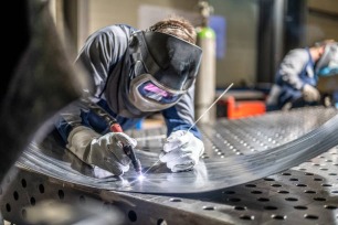
(Istock)
Working with sheet metal is an exercise in thermal discipline. While the fundamental principles of welding remain the same, thin-gauge fabrication demands a shift in mindset. You aren't just managing a puddle — you are managing a delicate heat balance where a fraction of a second can be the difference between a clean bead and a ruined workpiece.
In a typical shop environment, we define sheet metal as anything under 6 mm, though the real challenge lies in the 0.5 mm to 3 mm range. At this scale, the margin for error is razor-thin. If your heat input is too aggressive, you’ll face immediate warping or the dreaded burn-through. Conversely, if you're too timid, you end up with cold-lap and zero structural integrity.
Sheet metal welding plays a critical role in modern fabrication, especially when working with lightweight panels and precision assemblies. Thin materials react quickly to heat, making control and preparation just as important as the weld itself. Whether you're building enclosures, automotive components, or custom industrial cabinets, the quality of the weld directly affects strength, alignment, and final fit.
Welding performance often depends on edge quality from the cutting stage, especially in laser-cut sheet metal parts.
In real production environments, welding is rarely a standalone process. It works alongside CNC cutting, laser processing, and precision bending to create complete sheet metal assemblies. At JLCCNC, sheet metal welding is integrated into a full fabrication workflow, from laser cutting and forming to controlled weld finishing, ensuring that parts meet dimensional tolerances without excessive distortion. Understanding how welding fits into the larger manufacturing process helps engineers design parts that are both strong and production-ready.
Definition of Sheet Metal Welding
Sheet metal welding is the process of joining thin metal sheets, generally under 6 mm thick, through localized melting and fusion. In practice, most sheet metal fabrication involves much thinner gauges, which require low heat input and precise control.
The key distinction between sheet metal welding and heavy structural welding lies in heat sensitivity. Thick plate welding can tolerate higher amperage and longer arc exposure without immediate distortion. Thin sheet metal cannot. Excessive heat leads to warping, burn-through holes, and surface discoloration.
Because of this, welding thin sheet often relies on techniques that distribute heat carefully, such as intermittent welds, stitch welding, or controlled short weld passes. Operators must constantly manage heat buildup across the part, especially in long seams.
The goal is not just joint strength. It is strength without distortion.
Common Applications of Sheet Metal Welding
| Application Area | Typical Products | Why Sheet Metal Welding Is Used | Key Challenge |
| Electrical Enclosures & Housings | Control boxes, equipment cabinets | Joins bent panels into rigid, sealed structures with clean, flush seams | Maintain cosmetic finish and dimensional accuracy |
| Automotive Panels | Body panels, reinforcement sections | Enables lightweight construction while preserving structural integrity | Prevent warping from excess heat input |
| HVAC & Industrial Cabinets | Ductwork, ventilation units, control cabinets | Ensures sealed joints and accurate fit for airflow and assembly | Maintain shape precision and alignment |
| Prototyping & Low-Volume Production | Custom assemblies, short-run parts | Allows rapid design iteration without expensive tooling | Control distortion while enabling flexibility |
Sheet Metal Welding Methods
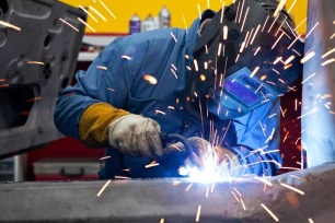
(Istock) MIG welding steel sheet in a metal fabrication workshop
Selecting the right sheet metal welding method depends on material thickness, production volume, cosmetic requirements, and heat sensitivity. Because thin sheet metal reacts quickly to heat, not every welding process is equally suitable. Engineers and fabricators must balance penetration, distortion control, speed, and finish quality.
Below are the most commonly used sheet metal welding methods for sheet metal fabrication and how they differ in practical applications.
MIG Welding for Sheet Metal
MIG (Gas Metal Arc Welding) is widely used in sheet metal fabrication because it offers good speed and ease of operation. It uses a continuously fed wire electrode and shielding gas to create the weld.
For thin sheet metal, lower amperage settings and short-circuit transfer mode are typically used to control heat input. This helps reduce burn-through and excessive distortion. MIG welding works well for production environments where efficiency and repeatability matter, such as automotive panels, enclosures, and light structural assemblies.
Advantages for sheet metal:
- Faster welding speed
- Easier to learn and operate
- Suitable for mild steel and stainless steel
- Good for moderate cosmetic requirements
Limitations:
- Higher heat input compared to TIG
- More spatter
- Less precise control on very thin gauges
MIG is often chosen when productivity is a priority and the material thickness allows some tolerance for heat.
If you're wondering about MIG vs MAG welding, check out our detailed guide.
TIG Welding for Thin Sheet Metal
TIG (Gas Tungsten Arc Welding) is preferred when precision and appearance are critical. It uses a non-consumable tungsten electrode and allows separate control of filler material.
TIG provides much finer heat control than MIG, making it especially suitable for very thin sheet metal and materials like stainless steel or aluminum. Fabricators often use TIG for visible weld seams where aesthetics and minimal distortion are important.
Advantages for thin sheet:
- Excellent heat control
- Cleaner welds with minimal spatter
- Superior appearance
- Better suited for ultra-thin material
Limitations:
- Slower process
- Requires higher operator skill
- Less efficient for large production runs
TIG welding is commonly used for custom fabrication, architectural metalwork, and precision enclosures where surface finish matters.
Spot Welding Techniques
Resistance spot welding is widely used in high-volume manufacturing, particularly in automotive body assembly. Instead of using filler metal, it joins sheets by applying pressure and electrical current to generate localized heat at the contact point.
Spot welding works best for overlapping sheet metal sections and is extremely efficient for repetitive production.
Advantages:
- Very fast cycle times
- Minimal added material
- Low visible distortion
- Highly automatable
Limitations:
- Limited to lap joints
- Requires access to both sides of the material
- Not suitable for all joint geometries
In automotive manufacturing, robotic spot welding systems join thousands of sheet metal points quickly and consistently.
Stop guessing about heat settings and distortion risks. Upload your CAD file and get an instant quote for precision sheet metal fabrication, including cutting, bending, and professional welding.
No back-and-forth. No vague pricing. Just real manufacturing feedback and fast turnaround.
Key Differences Between MIG, TIG, and Spot Welding for Sheet Metal
Understanding the key differences between welding methods helps engineers and fabricators choose the right process for their specific sheet metal applications. Here's a concise comparison:
- MIG welding offers higher productivity but introduces more heat, which can increase the risk of warping on thin sheet metal.
- TIG welding provides superior precision and cleaner welds, making it ideal for thin gauges or visible seams.
- Spot welding is best suited for lap joints in high-volume production, ensuring fast and repeatable results.
- Pulse welding settings reduce average heat input, helping to prevent burn-through and distortion on delicate panels.
- Laser welding minimizes distortion and delivers highly precise welds for thin sheet metal in precision assemblies, such as electronics or medical enclosures.
This summary gives a quick reference for selecting the appropriate welding method, balancing productivity, precision, and heat control.
Materials and Preparation in Sheet Metal Welding
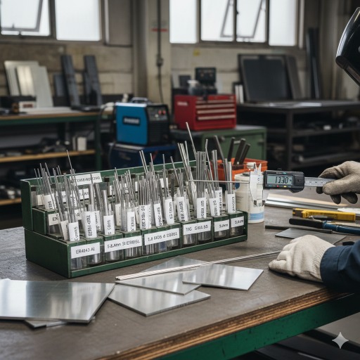
(AI generated) Different welding filler rods and thin sheet metal samples on factory workbench
Before you weld thin sheet metal, the material itself matters more than people think. Steel and aluminum don’t behave the same under heat, and if you treat them the same way, one of them will punish you for it.
With thin material, you don’t have the luxury of excess heat. The prep work is what keeps the weld stable.
Welding Sheet Steel vs. Aluminum
Welding sheet steel is usually easier to deal with. It doesn’t pull heat away as aggressively as aluminum, so your weld pool stays more predictable. You can dial in your settings and get consistent fusion without chasing the puddle around the joint.
Aluminum is different. It spreads heat fast. At first, it feels like nothing is happening — then suddenly the material collapses. That's because aluminum conducts heat quickly but melts at a lower temperature than steel. Once it reaches that threshold, it moves fast.
There's also the oxide layer. Aluminum naturally forms an oxide skin that melts at a much higher temperature than the base metal underneath it. If you don’t clean that off properly, penetration becomes inconsistent and the weld looks rough.
That's one reason AC TIG is commonly used for thin aluminum sheet, it helps break that oxide layer during welding.
Steel is generally more forgiving. Aluminum demands attention.
Surface Preparation and Joint Design
Thin sheet welding exposes every shortcut.
If there's oil, paint, or coating on the surface, you'll see it in the weld immediately. Porosity, unstable arc, contamination, all of it shows up faster on thin material because there's less mass to absorb mistakes.
Clean the joint area. Degrease it. On aluminum, brush off the oxide layer right before welding. On steel, remove coatings and scale so the arc stays stable.
Fit-up matters just as much. Big gaps force you to add more filler and more heat, which increases distortion risk. Tight joints let you weld cooler and cleaner.
And clamp your parts. Thin panels move when they heat up. If they're not restrained, they'll shift, and once they shift, they rarely come back perfectly flat.
When working with thin sheet metal, preparation isn't optional detail work. It's what keeps the weld from warping, cracking, or collapsing.
Bending sequence and flange design also influence how much heat distortion occurs during welding.
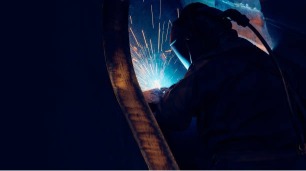
Welding Thin Sheet Metal: Challenges and Solutions
(Istock)
Welding thin sheet metal is much more demanding than working with thick plate. Because thin material lacks the thermal mass to soak up heat, temperatures spike almost instantly, leading to easy melt-through and warping. Even for an experienced welder, maintaining structural integrity and dimensional accuracy requires a major shift in technique and parameters. For engineers and fabricators, understanding these physical challenges is the only way to choose the right joint designs and weld settings.
Common Challenges in Welding Thin Sheet Metal
Burn-through
Burn-through occurs when excessive heat melts completely through the sheet, leaving holes in the material. Thin metal cannot tolerate prolonged arc exposure or high amperage. Small variations in travel speed or arc length can quickly cause failure, especially at edges or gaps.
Warping and Distortion
Thin sheet metal expands rapidly when heated and contracts during cooling. Because the material is flexible, uneven heating causes it to pull and twist. Long continuous weld beads often result in visible warping, especially in flat panels such as enclosures or automotive skins.
Inconsistent Penetration
Maintaining consistent fusion without overheating is difficult. Too little heat produces weak welds with poor penetration. Too much heat causes distortion or burn-through. Finding the narrow operating window between these two extremes is the core challenge of thin sheet welding.
How to Prevent Warping and Burn-Through
Lower Amperage Settings
Reducing amperage is the first step when welding thin sheet metal. Lower current minimizes heat input and reduces the risk of burn-through. It is better to use multiple controlled passes than one overly hot weld.
Pulse Welding
Pulse welding alternates between high and low current levels, allowing the material to cool slightly between pulses. This reduces average heat input while still achieving adequate penetration. Pulse MIG or TIG is especially useful for ultra-thin sheet and precision assemblies.
Stitch or Skip Welding
Instead of running a continuous bead, weld short segments spaced apart. This technique allows heat to dissipate between welds and reduces cumulative distortion. After completing initial tacks, additional passes can fill gaps gradually while maintaining panel stability.
Copper Backing Bars
Placing a copper backing bar behind the weld area helps absorb excess heat and supports the molten pool. Copper’s high thermal conductivity reduces burn-through risk and improves bead control. It is particularly effective when welding thin gaps or edges.
Key Parameters in Sheet Metal Welding
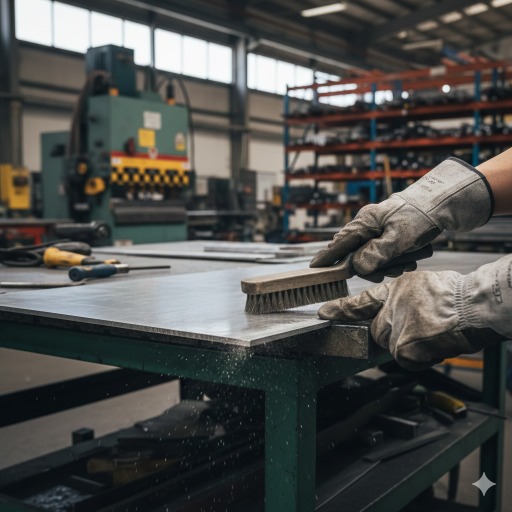
(AI generated) Technician cleaning aluminum sheet metal surface with wire brush before welding in a fabrication workshop
Thin sheet metal doesn't give you much room for error. Small adjustments in settings can mean the difference between a clean seam and a warped panel. When weld quality starts slipping, it's almost always one of these parameters that’s off.
You don't fix thin sheet problems by adding power. You fix them by controlling it.
Heat Input and Travel Speed
Heat input is everything with thin sheet metal.
Too hot, and you blow through the edge. Too cold, and the weld just sits on top without proper fusion. The trick is balancing amperage with travel speed so the puddle forms quickly and moves before heat builds up.
If you move too slowly, heat accumulates and distortion starts creeping across the panel. If you move too fast, penetration becomes inconsistent.
On thin material, you're not trying to lay down a heavy bead. You're trying to fuse the joint cleanly with the least total heat possible. Short arc length, steady hand, controlled motion.
It's controlled restraint, not brute force.
Filler Material Selection
Filler rod or wire choice matters more than many beginners realize.
On steel, matching filler to base material is usually straightforward. But even then, wire diameter affects control. Thinner wire gives better control for thin sheet because it feeds less material into the puddle at once.
Aluminum is more sensitive. The wrong filler can increase cracking risk or reduce corrosion resistance. For thin aluminum, common fillers like 4043 or 5356 behave differently in terms of fluidity and strength. The choice depends on whether appearance, strength, or corrosion performance is the priority.
Using oversized filler on thin material just forces more heat into the joint. Smaller diameter filler generally offers better control.
Joint Type and Welding Position
Joint design changes everything.
Butt joints on thin sheet are clean but unforgiving. Any gap increases burn-through risk. Lap joints are easier to control but add material thickness. Flanged edges help stiffen panels and reduce distortion.
Welding position also affects heat control. Flat position gives you the most stability. Vertical or overhead positions increase difficulty because gravity influences the puddle.
When possible, position the workpiece so you weld flat. It reduces variability and gives you better consistency, especially on thin gauges.
Recommended Key Parameters for Sheet Metal Welding
| Welding Method | Material Thickness | Amperage Range | Travel Speed | Notes / Tips |
| MIG Welding | 0.5 – 3 mm | 30 – 90 A | 30 – 100 cm/min | Use short-circuit transfer mode to reduce heat; avoid continuous long beads |
| TIG Welding | 0.5 – 3 mm | 20 – 70 A | 20 – 80 cm/min | Excellent for thin gauges and visible seams; AC TIG for aluminum |
| Spot Welding | 0.8 – 3 mm | 4 – 8 kA (peak) | 0.1 – 0.5 sec per spot | Best for lap joints in high-volume production; use proper electrode force |
| Pulse MIG/TIG | 0.5 – 2 mm | 20 – 60 A | Adjustable pulse frequency | Reduces average heat input; ideal for ultra-thin panels |
| Laser Welding | 0.2 – 2 mm | 400 – 800 W (laser power) | 200 – 500 mm/min | Minimal distortion, high precision; typically used in electronics/medical enclosures |
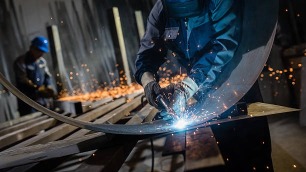
Sheet Metal Welding Tips for Preventing Warping
(Istock)
There's theory and then there's what actually works when you're standing at the bench.
Thin sheet welding rewards patience. Rushing almost always shows up later as distortion or uneven seams.
Sheet Metal Welding Tips for Beginners
Start with positioning. Especially with spot welding or tack welding, alignment is everything. If panels aren’t square before you weld, the heat will lock the misalignment in place.
Don’t run one long weld bead across thin sheet. That’s how panels warp. Instead, use multiple short welds spaced along the joint. Let each section cool before filling in between them. This spreads heat and reduces pull.
If something feels too hot, it probably is. Pause. Let it cool. Thin sheet responds quickly, both to heat and to restraint.
And practice on scrap of the same thickness. Thin metal behaves differently than thick stock. Muscle memory matters.
Best Practices for Professional Results
Plan your welding sequence before you start.
On larger panels, alternating weld locations helps balance heat. Jump from one end to the other instead of moving straight down the seam. That prevents cumulative distortion in one direction.
Post-weld straightening is often part of the process, not a sign of failure. Controlled mechanical correction, using clamps or light forming, can bring panels back into tolerance. The key is not overheating them during correction.
Professionals don't rely on one perfect pass. They rely on controlled heat, sequencing, and consistency.
Thin sheet metal welding isn't about pushing limits. It's about managing them.
Advanced Techniques and Innovations
Once you move beyond small-batch fabrication, consistency becomes more important than raw skill. Thin sheet metal is sensitive to heat variation, and even experienced welders introduce small differences from seam to seam. That’s where automation and newer welding technologies step in.
Advanced methods aren’t about replacing fundamentals. They're about controlling variables more precisely than a human hand can over long production runs.
Robotic and Automated Sheet Metal Welding
Robotic welding is common in industries where thin sheet assemblies are produced at scale, automotive body panels are the obvious example.
Robots don't get tired. They don't change travel speed halfway through a seam. Once parameters are dialed in, they repeat them exactly. That consistency dramatically reduces distortion variation between parts.
In thin sheet applications, automation helps in two main ways:
First, it stabilizes heat input. Travel speed, arc length, and dwell time stay consistent from weld to weld.
Second, it improves positioning accuracy. In spot welding, precise electrode placement ensures uniform weld nuggets and reduces weak joints.
Automated systems are especially useful for:
- Repetitive lap joints
- High-volume enclosure manufacturing
- Automotive sheet assemblies
- Precision cabinet production
However, automation only works well if joint fit-up and fixturing are already controlled. Robots don’t compensate for poor prep.
Welding Innovations for High-Precision Projects
For high-precision sheet metal work, newer technologies focus on minimizing heat input while maintaining fusion.
Pulse welding systems allow better puddle control on ultra-thin material. By cycling current between high and low levels, they reduce average heat while maintaining penetration.
Laser welding is another innovation gaining traction in precision fabrication. It offers extremely focused heat input, which significantly reduces distortion compared to traditional arc welding. It’s often used in electronics enclosures, medical devices, and thin stainless assemblies where cosmetic finish and dimensional accuracy are critical.
There's also improved inverter-based power sources that provide tighter arc control and more stable output on low amperage settings. For thin sheet, that control matters.
The trend is clear: better heat control, tighter consistency, less distortion.
If you're building a prototype enclosure or scaling production panels, JLCCNC will deliver precision sheet metal fabrication with controlled welding and consistent quality.
Upload your files today, get transparent pricing in minutes, and move your project forward with confidence.
Key Takeaways for Sheet Metal Welding
-Control heat input carefully – balance amperage and travel speed to prevent warping or burn-through.
-Use smaller filler wire or rods – ensures precise control on thin sheet metal and reduces excess heat.
-Plan your welding sequence – alternate weld locations to evenly distribute heat and minimize distortion.
-Minimize continuous weld beads – use stitch or skip welding to allow cooling between passes.
-Ensure proper joint fit-up and clamping – tight, secure panels reduce heat-related movement.
-Select the right sheet metal welding methods – choose MIG, TIG, or spot welding based on material, thickness, and cosmetic requirements.
FAQs
What is the best welding method for thin sheet metal?
There isn’t one universal answer. TIG welding offers the most heat control and is often preferred for very thin material or visible seams. MIG welding works well for production environments when properly set to low amperage. The best method depends on thickness, material type, and cosmetic requirements.
Can you weld thin sheet metal without warping?
You can minimize warping, but eliminating it completely is difficult. Lower heat input, stitch welding, balanced weld sequencing, and proper fixturing all reduce distortion. Controlling heat buildup is the key.
MIG vs TIG welding for sheet steel: which is better?
TIG provides better control and cleaner appearance, making it ideal for thin, visible sheet steel. MIG is faster and more efficient for production work. If appearance and precision matter most, TIG usually wins. If speed and throughput matter more, MIG is often preferred.
What thickness is considered thin sheet metal for welding?
In welding terms, sheet metal under about 6 mm is generally considered thin. However, most fabrication challenges begin well below that, typically in the 0.5 mm to 3 mm range, where heat control becomes critical.
Popular Articles
• 9 Sheet Metal Cutting Problems and Solutions
• Hole cutting in sheet metal: techniques, tolerances and applications
• Introduction to Sheet Metal Processing: Techniques and Tools for Precision
• Bending and Forming Technology in Sheet Metal Processing
• Laser cutting technology in sheet metal processing
Keep Learning
Ultrasonic Welding Guide: How It Works, Materials, Applications, and Benefits
Key Takeaways - Ultrasonic welding uses high-frequency mechanical vibrations to create solid-state welds without melting materials - It works exceptionally well for thermoplastics and many metals, especially dissimilar combinations - The process is fast, clean, and requires no additional adhesives or fillers - Different applications require specific frequency and power configurations - Initial equipment costs are higher, but operating costs are typically lower than alternative methods Introduction Ult......
Hot Rolled vs Cold Rolled Steel: Key Differences, Cost, and Applications
Key Takeaways • Hot rolled vs cold rolled steel comes down to processing history: hot rolled steel is shaped at high temperature, while cold rolled steel is further processed at room temperature for better surface finish and tighter tolerances. • In sheet metal applications, cold rolled steel is usually preferred for enclosures, panels, and precision parts because it offers smoother surfaces and more consistent thickness. • Hot rolled steel is typically better for structural frames, supports, and heav......
Aluminum vs Stainless Steel: Which Sheet Metal Material Is Better?
Note • Aluminum vs stainless steel is not a one-answer choice; the better material depends on weight, strength, corrosion exposure, fabrication method, and total cost. • Aluminum is much lighter, easier to machine, and often less expensive, making it a strong choice for enclosures, panels, and weight-sensitive sheet metal parts. • Stainless steel offers higher absolute strength, better stiffness, and stronger corrosion resistance in harsh environments such as marine, chemical, and food-processing appl......
Metal Mesh Sheets: Types, Sizes, Materials & Custom Fabrication Guide
What Is a Metal Mesh Sheet? (AI generated) metal mesh sheet showing precise grid structure A metal mesh sheet is a material formed by interlacing, welding, or expanding metal into a network of controlled openings. It is widely used where airflow, visibility, or weight reduction is required without sacrificing structural support. A metal mesh sheet is a sheet formed by interlacing, welding, or expanding metal into a network of openings. Those openings are controlled. Size, spacing, and pattern all affe......
Anchor Fasteners for Sheet Metal: Best Types for Concrete and Industrial Use
What is an Anchor Fastener in Sheet Metal (AI generated) Technician securing a sheet metal enclosure Even the most precisely engineered sheet metal part is useless if it isn’t secured properly. In a real-world installation, parts don't exist in a vacuum. Enclosures have to be bolted to shop floors, brackets have to carry heavy piping, and panels have to withstand constant machine vibration. The stability of the entire assembly depends on how it is connected to the base material, usually concrete or ma......
Sheet Metal Deburring: Methods, Tools & How to Deburr Metal and Aluminum
(AI generated) Sheet metal production workflow In this guide, we’ll cover: - What sheet metal deburring is and why it matters - Common burr formation mechanisms - Deburring methods and their trade-offs - How to deburr different metals effectively - Design tips to reduce burr formation Sheet Metal Deburring Methods (Quick Comparison) Method Best For Speed Notes Manual Small jobs Slow Precise, low cost Abrasive Belt Flat sheets Fast Uniform finish Brush Light burrs Fast Good for deburring aluminum Vibra......