CNC Knurling Guide: Types, Patterns, and Design Tips
19 min
- What Is Knurling in CNC Machining (Definition and Purpose)
- How Knurling Works on CNC Lathes
- Types of Knurling Patterns (By Function)
- Does Knurling Change Part Diameter?
- How to Select the Right Knurl Pattern
- CNC Knurling Process Considerations
- Design Guidelines for Knurled Parts (DFM)
- Common Knurling Defects and How to Avoid Them
- Knurling vs Other Surface Texturing Methods
- When to Use CNC Knurling
- FAQs About Knurling
Key Takeaways About CNC Knurling
- A CNC knurling feature is used where friction or retention is required. Typical use cases include hand grips, thumb screws, and press fit interfaces.
- Pattern choice is not arbitrary. The main types of knurling are straight, diamond, and helical. Among standard knurling patterns, diamond is preferred for general grip since it works in multiple directions. Straight patterns are used when movement is mostly axial.
- Knurling changes size. The resulting knurling texture pushes material outward, increasing the outer diameter. This needs to be factored in before machining, especially for tight fits.
- Process limits matter. Material, tool condition, and feed control how clean the pattern forms. Softer metals respond well to forming, while harder materials often need cut knurling for consistency.
- Design intent should be clear early. The grip, pitch, and depth should match the user interaction. For interference, the pattern needs to hold without damaging the mating part.
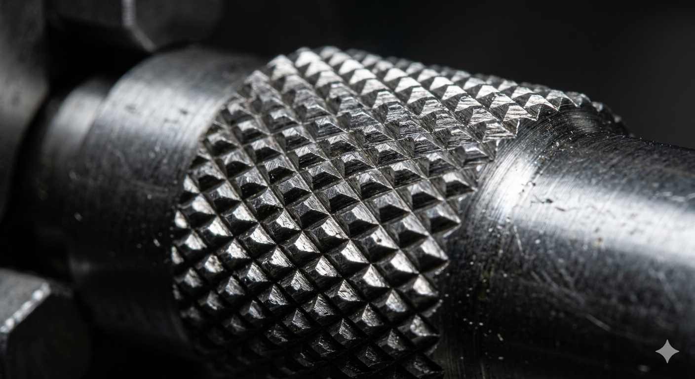
(AI generated) diamond knurl pattern on cylindrical metal part
Knurling in CNC machining is a surface operation where a tool forms a defined pattern on a part surface, either by displacing material or cutting it, to improve grip or support mechanical fit.
In practice, this is a functional feature. The knurling definition sits closer to surface engineering than surface finishing in machining. It affects how a part is held, assembled, and performs under load. In CNC knurling machining, this process is used when surface grip or retention cannot be achieved through geometry alone.
This article covers how knurling works mechanically, what pattern and pitch selection actually depend on, and where the process limits are. If you're designing a knurled feature for a CNC part, the decisions you make before machining starts determine whether the pattern forms clean or causes problems at assembly.
What Is Knurling in CNC Machining (Definition and Purpose)
Knurling is a machining process that creates a patterned texture on a surface by deforming or cutting material. It is primarily used to improve grip, increase friction, or create mechanical interference between parts.
In CNC machining, knurling is applied to cylindrical components such as shafts, knobs, and fasteners where surface interaction affects performance.
Unlike standard finishing processes, knurling directly modifies surface geometry to achieve functional contact under load rather than improving appearance.
Where Knurling Is Used in Parts
Knurling is applied in parts where surface interaction plays a functional role, particularly when grip, torque transfer, or mechanical retention cannot be reliably achieved through smooth surfaces alone.
In hand-operated components such as knobs, thumb screws, and adjustment dials, knurling improves grip by increasing friction between the user and the part surface, reducing slip during operation.
In press-fit and retention applications, knurling enhances mechanical engagement between mating components. The raised pattern creates localized interference, which helps secure parts in softer materials like plastics or light alloys without additional fasteners.
Knurling is also used on shafts or rotating components where torque must be transmitted without slippage. The textured surface improves friction at the interface, reducing reliance on keys, pins, or adhesives in certain designs.
However, knurling is not suitable for precision mating surfaces, sealing interfaces, or components requiring tight dimensional control. Since the process alters the outer diameter and introduces surface irregularity, it can negatively affect fit and alignment in high-precision assemblies.
How Knurling Works on CNC Lathes

(AI generated) CNC knurling process
A CNC knurl is generated by pressing or cutting a patterned tool into a rotating workpiece while maintaining synchronized feed. The tool contacts the surface under load. That contact defines how material flows and how clean the knurling texture forms.
Contact mechanics drive the result. Forming pushes material outward and sideways. Cutting removes material along the pattern path. Both change surface geometry, but they load the machine differently. Forming loads spike fast, especially on harder alloys. Cutting distributes load more evenly compared to forming but needs stable tool alignment.
Feed and spindle speed must stay in sync with the pattern pitch. If the feed rate does not match the circumferential spacing of the knurling patterns, the tool will not track its own impression. That is where double tracking and torn patterns show up. Most tracking issues come from incorrect feed per rev or starting on a mismatched diameter.
Forming vs Cutting Knurling
Forming displaces material. No chips. The surface work hardens, and the outer diameter grows. This is common for softer metals and high-volume runs where cycle time matters.
Cutting shears the pattern. Chips form. The load on the spindle is lower and more predictable. This approach works better on harder materials or when pattern clarity matters more than speed.
Both are valid types of knurling. The choice depends on material behavior, tolerance limits, and machine rigidity.
Tool Engagement and Pressure Mechanics
The tool must engage square to the axis with consistent radial pressure. Too little pressure gives a shallow, incomplete knurling texture. Too much pressure crushes peaks and distorts the pattern.
Initial engagement matters. The tool should seat quickly to full depth to avoid partial tracking marks. A slow ramp often creates double impressions that stay visible across the surface.
Rigidity controls consistency. Any deflection at the toolpost or part will show up as an uneven pattern depth.
Feed Synchronization and Pattern Tracking
Tracking depends on matching feed per revolution to the pattern pitch. The tool must re-enter the same groove on each pass. If not, it cuts a new path. That produces a doubled or smeared knurling pattern.
Diameter also plays a role. If the starting diameter does not align with the pitch, the pattern will fight itself even with correct feed. Some setups adjust the diameter slightly to lock tracking.
Types of Knurling Patterns (By Function)
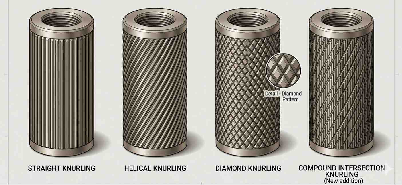
(AI generated) Illustration of different knurl patterns
Knurling patterns are defined by tool geometry and orientation relative to the part axis. That geometry controls how the surface carries load and how it feels under contact. No guesswork here.
Most CNC applications use three baseline types of knurling. Straight, diamond, and helical. Variants exist, but they don’t change the underlying behavior.
Straight Knurl (Axial Grip)
Straight knurling runs parallel to the axis. The tool angle is effectively 0°.
It creates linear ridges. Contact stays directional.
It is used where force is applied along the axis. Push fits, sliding parts, or components that rely on controlled axial grip. The surface resists motion in one direction and does very little outside it.
Diamond Knurl (Multi-direction Grip)
Diamond knurling patterns are formed by two opposing tracks, typically set around 30° to the axis.
This creates a cross-hatch knurling texture with point contact instead of lines.
Grip works in multiple directions. Load spreads across peaks instead of along ridges. That is why it shows up on most hand-operated parts. Better traction. More forgiving under wear.
Helical and Special Patterns (Load Distribution / Special Cases)
Helical knurling follows a spiral path along the surface.
Contact moves along a continuous path instead of intersecting lines. That changes how force transfers during rotation or sliding contact.
Used in cases where smoother engagement or directional feel matters. Less common in standard production. Setup is more sensitive, and small errors show up quickly in the pattern.
Does Knurling Change Part Diameter?
Yes. Knurling changes the diameter because the surface is no longer smooth. Material moves or is cut, and the outer profile shifts. This is expected, not an edge case.
Material Displacement
In forming knurling, the tool pushes material outward under pressure. No chips. The peaks are displaced metal, so the effective OD grows.
In cut knurling, the tool removes material along the pattern. Growth is lower, but the surface still deviates from the original diameter.
Diameter Increase Range
The increase is variable. It depends on pitch, depth, and material.
For forming knurling, shops typically see a range of ~0.02 mm to 0.15 mm, depending on pitch and material. Softer materials like aluminum can go higher if pressure is not controlled. Harder alloys stay on the lower end.
Not a fixed number, just a working range.
Tolerance Impact
This is where it fails in production.
You don’t hit the final size before applying a knurling texture. You undersize, then knurl to land within tolerance.
Also, measurement is not straightforward. Calipers read peak to peak. Functional fit depends on how those peaks compress under load.
If the part mates with another component, design around the knurled condition. Not the pre knurl diameter.
In tight tolerance assemblies, knurling should be treated as a variable geometry operation rather than a predictable dimensional offset.
How to Select the Right Knurl Pattern
Pattern selection is a constraint match, not preference. You’re aligning function, material behavior, and geometry limits. Miss one variable and the part either slips or goes out of size.
Grip vs Appearance Trade-offs
Start with function requirements. That decides everything downstream.
Grip-driven parts need high surface engagement. Diamond patterns dominate because they distribute contact in multiple directions. Straight patterns stay narrow in use, mainly for axial load transfer.
Appearance-driven parts reduce surface aggression. That usually means finer pitch and shallower engagement, but it reduces usable friction.
| Decision factor | Grip priority | Appearance priority |
|---|---|---|
| Pattern geometry | Diamond, straight | Fine diamond, light helical |
| Surface engagement | High | Controlled |
| Pitch range behavior | Coarser spacing increases bite | Finer spacing reduces visual noise |
| Functional risk | Wear and aggressive contact | Slippage under load |
No overlap in intent. If you try to optimize both equally, you get neither.
Material Hardness and Pattern Quality
Material decides whether the knurling texture forms clean or collapses.
Soft metals like aluminum and brass form sharply under standard forming pressure. Carbon steels generally fall between these extremes. Stainless and hardened alloys resist deformation and push the process toward cut knurling or tool reinforcement.
| Material class | Pattern formation behavior | Process stability |
|---|---|---|
| Aluminum | Clean displacement, sharp peaks | Stable |
| Brass | Very stable formation | Stable |
| Mild steel | Acceptable with correct pressure | Moderate |
| Stainless steel | High tool load, risk of tearing | Unstable in forming |
| Hardened alloys | Poor forming response | Requires cutting |
Wrong pairing shows up as crushed peaks or torn ridges immediately.
If your design involves tight diameter control or specific pitch requirements, it is often necessary to validate the knurling behavior before production. JLCCNC can review your CAD file to check pitch compatibility, diameter growth, and manufacturability based on real machining constraints. Upload your file, and our engineers will review the geometry, flag any tolerance or diameter considerations before production starts, and give you a quote without the back-and-forth.

Precision CNC Machining Service
Professional manufacturing, fast turnaround, and quality assurance.
Manufacturing Constraint and Diameter Limit
Knurling is geometry shifting under load. That shift is not optional.
Diameter increases after forming. Pitch must align with the circumference, or tracking fails. If the feed per revolution is off, the tool stops following its own path and starts cutting a second pattern.
| Constraint | What actually happens |
|---|---|
| Incorrect pitch to diameter match | Double tracking or pattern smear |
| No pre-machining offset | Final OD exceeds tolerance |
| Small diameter parts | Higher risk of pattern overlap instability |
| Large diameter parts | More stable pattern registration |
There is no in-process correction once a mismatch propagates through the pattern. The machine repeats the error every revolution.
Pattern selection is ultimately a constraint resolution problem between grip requirement, material response, and allowable dimensional variation.
CNC Knurling Process Considerations
Knurling process control is about stability under load. If pressure, rigidity, or feed sync drift even slightly, the surface carries it through the full rotation. No effective in-process correction exists once the cut starts.
Diameter Growth and Tolerance Impact
In forming CNC knurl operations, the surface is displaced outward. That shifts the final diameter beyond the pre-machined value.
Growth is variable. It depends on material response, tool depth, and pitch engagement. In production environments, engineers typically treat it as a non-constant offset, not a fixed allowance.
Common shop behavior range:
- Aluminum: ~0.03 to 0.12 mm radial expansion
- Mild steel: ~0.02 to 0.10 mm
- Stainless steel: inconsistent growth due to higher deformation resistance
Cut knurling avoids most outward displacement, but it still changes geometry through material removal. Either way, the final OD is not the same as the starting OD.
If you don’t compensate before machining, the tolerance stack fails at the assembly stage.
Tool Pressure and Machine Rigidity
Pressure defines surface integrity.
Low pressure:
- incomplete impression
- weak knurling texture formation
- pattern fade under load
High pressure:
- peak collapse
- surface tearing
- accelerated tool wear
Machine rigidity controls whether that pressure stays stable. Any deflection in toolpost, spindle, or workholding translates directly into uneven depth.
The key failure pattern is not tool damage. It is an inconsistent engagement force across rotations. Once that starts, the pattern cannot self-correct.
Rigid setup equals repeatability. Flexible setup equals variation. The variation remains visible in the final pattern.
Surface Finish and Consistency Control
Surface consistency depends on keeping tracking stable through the full cycle.
Main instability sources:
- feed per revolution mismatch causing double tracking
- diameter misalignment breaking pitch lock
- vibration introducing uneven peak formation
Once a clean track is established, it must remain synchronized. If it breaks even once, the tool starts cutting a second path. That defect propagates around the full circumference.
Consistency improves when:
- spindle speed remains stable under load
- feed per rev matches pattern pitch exactly
- engagement pressure stays constant after initial contact
- workholding eliminates micro movement
Design Guidelines for Knurled Parts (DFM)
Design for knurling is mostly constraint management. You’re not adding a surface feature; you’re forcing controlled deformation on geometry that already has limits. If those limits are ignored, the pattern fails before it even forms.
Recommended Diameters and Pitch Matching
Knurl performance depends on pitch to circumference alignment. If the feed per revolution does not match the knurl pitch, the tool will drift and create double tracking.
As a working constraint, common industrial knurl pitches typically fall in the 0.3 mm to 1.6 mm range, but usable selection depends on part diameter, not preference.
Condition-based rules: Small diameters increase tracking sensitivity. Larger diameters stabilize pattern registration. Poor pitch match leads to overlap, tearing, or ghosting.
There is no universal diameter-to-pitch ratio. It is a synchronization problem between geometry and spindle rotation.
Avoiding Thin Walls and Deformation
Thin-wall sections react poorly to forming knurling because the process introduces radial force.
When the wall thickness is low, the material does not support uniform displacement. The result is ovalization, local collapse, or uneven knurling texture depth.
Typical failure condition: wall flexes under tool load, pattern depth varies across circumference, part loses roundness after forming.
The design rule is simple. If the wall cannot resist radial compression, the knurl will not stay uniform.
This becomes more critical in softer materials where displacement is easier but structural recovery is weaker.
Allowances for Post-Knurl Finishing
Post-processing after knurling is limited. Once the surface is displaced, you are no longer working with a clean datum.
If secondary finishing is required, grinding or turning after knurling will remove peak definition, polishing reduces functional grip area, and re-machining can distort pattern geometry completely.
Common Knurling Defects and How to Avoid Them
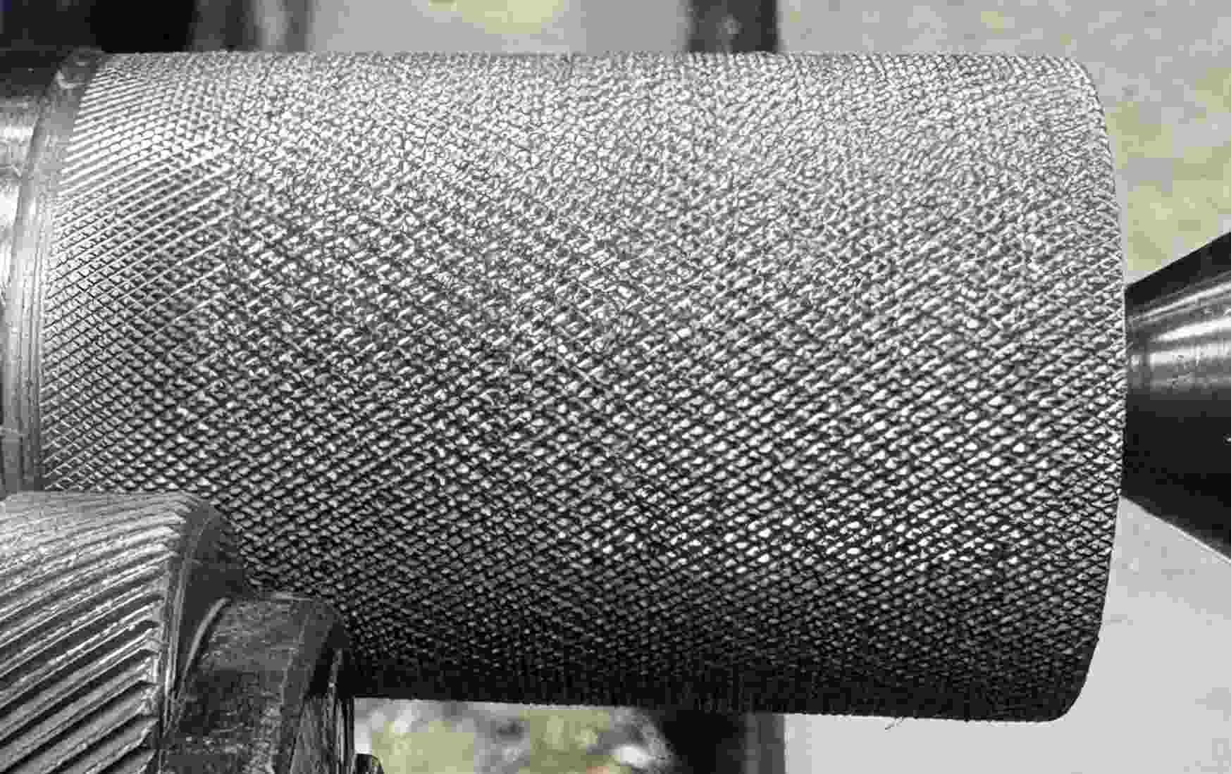
(Reddit) Knurling failure
Double Tracking and Pattern Misalignment
This happens when the tool loses a single locked groove and starts generating a second path.
The root cause is feed and pitch mismatch. The tool stops synchronizing with the surface and shifts into an alternate track.
It can also appear if initial engagement is unstable or if spindle speed changes during contact.
Fix is setup level only. Feed per revolution must match pitch before engagement. The first bite has to lock clean.
Once it splits, the pattern cannot be recovered.
Surface Tearing and Material Smearing
This is overloaded at the contact zone.
Excess pressure collapses the forming process. Instead of a defined knurling texture, the material flows unevenly or tears at the peaks.
Soft materials smear under uncontrolled load. Hard materials fracture when force exceeds surface stability.
Worn tooling increases the effect because it drags instead of forming.
Correction is pressure control at entry and maintaining a stable load after contact. Tool condition must be verified before cutting.
Inconsistent Depth and Visual Defects
Depth variation comes from instability during rotation.
Any micro movement in the toolpost or workholding translates into uneven peak height around the part.
Material inconsistency along the stock can amplify the effect, with different resistance zones producing different depths.
Knurling vs Other Surface Texturing Methods
Surface texturing is chosen based on how the surface is supposed to carry the load. Knurling modifies geometry. Machining removes material. Coatings sit on top. Same goal, different physics.
Knurling vs Machined Texture
Machined texture is defined by toolpath removal. The cutter subtracts material and builds patterns through geometry loss. Dimensions stay stable because nothing is displaced outward.
Knurling behaves differently. The tool forces material to move or locally shear, so the surface becomes a deformed structure. That is why the diameter shifts after the operation.
From a production standpoint, machined textures scale with toolpath complexity and cycle time. Knurling scales with setup sensitivity and tool engagement stability.
| Aspect | Knurling | Machined Texture |
|---|---|---|
| Primary mechanism | Plastic deformation or localized cutting | Material removal |
| Dimensional behavior | OD increases due to displacement | Nominal geometry retained |
| Pattern formation | Surface flow into tool geometry | Controlled cut path |
| Production driver | Setup + engagement stability | Toolpath time + programming |
Knurling vs Coating or Blasting
Coating and blasting do not build structural geometry. They modify only the surface layer condition.
Blasting works through controlled abrasion. It increases micro-roughness, which improves friction but does not create load-bearing features. Coatings change surface chemistry or add a thin protective layer, which can alter feel but not geometry.
Knurling creates a permanent geometric structure. The surface itself becomes the functional interface under load, not just a treated layer.
Blasted and coated surfaces depend on surface integrity staying intact. Knurled surfaces depend on geometry, which degrades more slowly under mechanical wear.
| Aspect | Knurling | Blasting | Coating |
|---|---|---|---|
| Surface principle | Structural deformation | Abrasive modification | Applied layer |
| Functional grip source | Geometry engagement | Friction increase | Surface energy / finish |
| Wear dependency | Geometry loss over time | Roughness degradation | Coating breakdown |
| Dimensional impact | Significant | Minimal | Minimal |
Decision point is physics instead of just preference. If load transfer depends on geometry, Knurling is one of the primary structural options when load transfer depends on surface geometry. If it depends on surface condition, blasting or coating is sufficient.
When Knurling Is Not the Right Choice
Knurling is not always the correct surface solution. In some cases, it introduces more risk than benefit.
Tight tolerance parts
Knurling changes the outer diameter through material displacement or removal.
For parts with strict dimensional limits or controlled fits, this variation makes tolerance control unstable. Machined surfaces are more predictable.
Thin-wall parts
Knurling applies radial force.
If wall thickness is low, the structure cannot support uniform deformation. This leads to ovalization, distortion, or inconsistent pattern depth in thin-wall machining.
Cosmetic-only surfaces
If the requirement is visual texture without mechanical load, knurling is not efficient.
Blasting or light machining achieves consistent appearance without changing geometry or adding process load.
When to Use CNC Knurling
Use CNC knurling only when the surface must do mechanical work. Not when it just needs to look finished. The decision sits between grip, retention, and surface constraints. If those don’t exist, knurling is an unnecessary load on the process.
Functional Grip Requirements
Knurling is justified when direct hand contact needs controlled friction. Typical use is where torque transfer or slip resistance is required under repeated handling.
This includes knobs, adjustment dials, and tool interfaces where smooth surfaces fail under load. The surface is designed to deform or cut into a stable grip structure, not just increase roughness.
If grip can be achieved through geometry alone (larger diameter, flats, or serration), knurling becomes redundant and adds only process complexity.
Press-Fit and Retention Applications
Knurling is used in retention only when interference depends on surface bite, not dimensional accuracy.
In plastic inserts or low-precision assemblies, the raised knurling texture improves mechanical lock by increasing the surface engagement area. This is not a precision fit strategy. It compensates for tolerance looseness.
It should be avoided in tight tolerance fits where dimensional stability is critical, because forming changes the diameter and introduces variability in engagement force.
Cosmetic and Branding Surfaces
Knurling is sometimes used for visual texture, but this is the lowest priority use case.
It creates a repeatable industrial pattern that signals “machined quality,” but it does not improve function in these cases.
If the goal is branding or surface identity without mechanical load, blasting or light machining finishes are more controlled and lower risk. Knurling adds unnecessary deformation and can complicate downstream finishing.
Knurling is a process that rewards getting the details right upfront—pattern, pitch, pre-machined diameter, and material all influence whether the finished part works or needs rework.
JLCCNC supports straight and diamond knurling in 0.8 mm and 1.0 mm pitch, with engineering review before machining to verify diameter growth, pitch tracking, and tolerance stack against real machine conditions.
Once the geometry is confirmed, you can upload your CAD file to receive a instant quote starting from $1, with lead times as short as 3 days depending on part complexity and setup.
Precision CNC Machining Service
Professional manufacturing, fast turnaround, and quality assurance.
FAQs About Knurling
Q: What is knurling in machining?
Knurling in machining is a process where a tool deforms or cuts the workpiece surface to create a patterned texture for grip or mechanical engagement.
Q: What are the main types of knurling?
The main types of knurling are straight, diamond, and helical patterns. They differ by tool geometry and surface contact direction.
Q: What causes double tracking in knurling?
Double tracking happens when feed per revolution does not match the knurl pitch. The tool stops following the original groove and starts forming a second path, usually due to sync mismatch at engagement.
Q: Does knurling change part diameter?
Yes. Forming knurling displaces material outward, increasing the outer diameter. The change is variable and depends on material, pitch, and applied pressure.
Q: Is knurling done by cutting or forming?
It can be both. Forming displaces material without chips, while cutting removes material to generate the pattern. Choice depends on material hardness and process stability requirements.
Popular Articles
• Cutting with Precision: A Comprehensive Guide to CNC Water Jet Technology
• CNC Coolant Explained: Types, Maintenance & Safety
• Rake Angle in Machining: Machinists’ Guide to Perfect Cuts
• What Steps Are Taken To Minimize Waste In CNC Machining Processes?
• How EDM Wire Cutting Works: Complete Guide to Precision CNC Wire Cutting
Keep Learning
Chatter in Machining: Causes, Effects, and How to Reduce It
CNC milling operation producing visible chatter marks on an aluminum workpiece Quick Chatter Diagnosis Checklist Symptom Most Likely Cause First Action High-pitched squeal Regenerative chatter Change spindle speed ±15% Chatter only in deep pockets Excessive tool overhang Shorten tool Chatter on thin walls Low workpiece rigidity Improve fixturing Chatter after tool replacement Runout / holder issue Check tool holder Chatter only during finishing DOC too small / rubbing Increase feed or adjust speed It ......
What Is Tool Offset in CNC? Types, Setup & Best Practices
CNC tool offset setup with measurement overlay Key Takeaways CNC offsets connect programmed intent with actual cutter position. Length data guides Z-axis depth control. Radius data protects part size during contour milling. Geometry values define the cutter's measured baseline. Wear values support fine correction during production. Verified data lowers scrap risk before full machining. Good offset habits protect tools, fixtures, and parts. In the context of CNC machining , tool offset is the quiet set......
Trochoidal Milling: Complete Guide to High-Efficiency CNC Machining
Key Takeaways Trochoidal milling combines circular cutter motion with continuous forward feed. The cutter normally engages 5 to 20% of its diameter instead of making a full-width cut. A smaller engagement angle limits force changes during slotting and pocket roughing. Low radial engagement often allows greater axial depths of cut than conventional slot milling. CAM software calculates the circular path automatically from the selected machining parameters. This strategy is widely applied to titanium, s......
What Is Die Casting? Process, Materials, and Applications
Key Takeaways Die casting is a metal casting process that forces molten metal into a reusable steel mold under high pressure, producing parts with tight tolerances and good surface finish at high volume. Aluminum die casting is the most common form by far, thanks to its combination of light weight, decent strength, and good corrosion resistance. The die casting process runs through mold preparation, injection, cooling, and ejection in a cycle that can repeat every few seconds to minutes depending on p......
First Angle vs Third Angle: Understanding Orthographic Projection Methods
Key Takeaways Orthographic projection is the system that lets a 3D part be represented through multiple 2D views, front, top, side, and so on. First angle projection and third angle projection are the two standard methods for arranging those views, and they place views in opposite positions relative to the object. First angle projection is the ISO standard used across most of Europe, India, China, Russia, and many other countries following ISO standards Third angle projection is the standard in the Un......
Micro EDM Machining: Capabilities, Materials, and Applications for Precision Components
Key Takeaways About Micro EDM Machining Only electrically conductive materials can be machined. Hole diameters can reach below 50 μm on specialized equipment. The process produces almost no mechanical cutting force, making it suitable for thin or delicate features. Surface integrity still requires attention because recast layers and heat-affected zones may remain after machining. Micro EDM is often combined with CNC machining, with milling producing the main geometry before EDM finishes critical micro......