Metal Punching Process: Sheet Metal Punching, Clearance & Force Guide
14 min
- Metal Punching Process
- Materials Suitable for Sheet Metal Punching
- Critical Parameters in Metal Punching
- Types of Metal Punching Operations
- Punching Machines and Tooling
- Common Problems in the Metal Punching Process
- FAQ
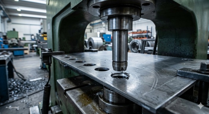
(AI generated) CNC machine performing a metal punching process on sheet metal during a punching operation in a fabrication workshop.
Metal punching is a sheet metal fabrication process that uses a punch and die to shear holes or shapes into sheet metal through mechanical force. The metal punching process is widely used for producing repetitive holes, ventilation patterns, and cutouts in high-volume manufacturing.
Spend ten minutes on the floor of a high-speed shop and you’ll notice that not all holes are created equal. You’ve got lasers for the complex work, drills for the heavy lifting, and then you’ve got the turret press. When a punch drops through sheet metal, it’s not just making a hole, it’s performing a high-speed mechanical shear. For the right job, nothing else comes close for throughput.
If you’re designing brackets, enclosures, or vented panels, punching is usually your fastest path to finished parts. Once the tool is indexed and the program set, the machine can produce consistent parts continuously.
It works because it’s pure physics. You’re using a hardened punch and die to force the metal past its shear strength until it snaps. It’s a clean fracture rather than a melt. When you’ve got your clearances dialed in, the edge quality is consistent, the cycle times are brutal, and you can scale from a prototype run to a five-figure production order without breaking a sweat.
The Mechanics: Punch vs. Die
Punching is just forcing a hardened punch through a sheet and into a matching die. The punching clearance between the punch and die edges is critical here to ensure clean shearing and minimal burr formation.
When that punch hits, it doesn’t just cut; it strains the material until it hits that breaking point. The material deforms, yields, and then shears along the edge of the die under the correct punching force. The slug pops out the bottom, and you move to the next position.
The goal here is total repeatability. Once you’ve set your tooling and cleared your station, you aren’t messing with positioning, the machine handles it. That’s why you see this on everything from electrical cabinets to perforated structural panels.
Punching vs. The Alternatives
Punching vs. Laser: Lasers are thermal. Laser cutting is amazing for complex, intricate geometries or if your design is still evolving and you don’t want to pay for hard tooling. But they’re slow on high-count hole patterns. Punching is mechanical. It’s fast, consistent, and brutal on simple geometry, but it lacks the laser's versatility.
Punching vs. Stamping: People confuse these all the time. Think of punching as a single operation, while stamping is the whole workflow. A progressive stamping tool is basically a sequence of operations, punching, bending, and forming, all happening in one press cycle. Punching is the tool; stamping is the process.
Punching vs. Drilling:CNC Drilling is subtractive and slow; it’s a rotating tool chewing through material. Punching is instantaneous. If you’re doing a thousand mounting holes, drilling is a waste of machine time. Punching knocks them out in the time it takes the ram to cycle.
| Process | How It Works | Strengths | Limitations | Best Use Cases |
| Punching | Mechanical shear using a punch and die | Fast for repetitive holes, consistent edges, and minimal setup | Less flexible for complex shapes | Mounting holes, brackets, perforated panels |
| Laser Cutting | Thermal cutting using focused laser beam | Very precise, handles intricate patterns, no hard tooling required | Slower for high-volume holes, heat-affected zones | Prototyping, complex geometries, small production runs |
| Drilling | Rotating cutting tool removes material | Good for deep holes, adjustable for different diameters | Slow for high-volume, tool wear, vibration issues | Low-volume or custom holes, thick materials |
| Stamping | Sequence of operations (punching, bending, forming) | High-volume production, can form complex parts in one cycle | Requires custom dies, high upfront cost | Mass production of enclosures, brackets, automotive parts |
Metal Punching Process

(Istock) Close-up of punch and die interaction during a sheet metal punching process showing the punching operation in progress.
Everything hinges on the interaction between the punch and the die. Correct punching clearance—the specific gap based on material thickness and type—is essential for achieving clean edges. Equally important is applying the proper punching force to shear the material efficiently without damaging the tooling.
- Positioning: The machine aligns the sheet.
- Contact: The punch hits the material.
- Deformation: The metal hits its elastic limit.
- The Shear: The material fails along the die edge.
- The Slug: The scrap drops through, and you’ve got a finished feature.
If your clearance is too tight, you’re going to burn through tooling and kill your ram pressure. If it’s too loose, you’re going to get burrs and inaccurate hole profiles. Get that balance right, and you don’t even need to touch the parts for secondary finishing.
Typical Punch and Die Interaction in Sheet Metal Punching
Hole edge quality hinges entirely on the relationship between the punch and the die. The most critical factor here is the punching clearance, the specific gap between the punch edge and the die opening. Maintaining the correct punching force ensures the metal shears cleanly along the die, producing consistent hole profiles with minimal burrs.
If that clearance is too tight, you’re spiking your force requirements and chewing through your tooling prematurely. Go too wide, and the material won't shear cleanly.. Instead, it tends to roll and deform, leaving you with massive burrs that require secondary cleanup.
Success in metal punching is about balancing these two extremes. When your punch geometry, die sizing, and punching clearance are optimized for the specific material, and the correct punching force is applied, the metal fractures precisely where intended, resulting in clean, repeatable hole edges. That’s how you get clean, consistent hole profiles that don't need any further work once they come off the machine.
Punching Operation in Sheet Metal Fabrication
The punching operation in sheet metal fabrication refers to a controlled shearing process where a punch tool forces material through a die opening to create a defined feature. Unlike machining processes that gradually remove material, punching separates the material in a single press stroke, making it highly efficient for repetitive operations.
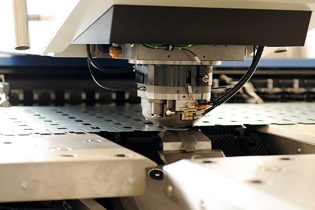
In modern fabrication environments, punching operations are commonly performed on CNC turret presses. These machines automatically position the sheet and select the appropriate punch and die combination, allowing multiple hole sizes or shapes to be produced without manual tool changes.
Depending on the design, a punching operation can create a variety of features, including round holes, slots, louvers, and ventilation patterns. Because the process relies on mechanical force rather than heat, it avoids thermal distortion and maintains consistent material properties around the cut edges.
For engineers designing sheet metal parts, understanding the limitations of a punching operation is important. Hole diameter, edge distance, and sheet thickness must be considered to ensure that the punch and die can operate without excessive tool wear or deformation of the surrounding material.
Many fabrication teams rely on platforms that allow engineers to quickly upload CAD files and evaluate manufacturability. While punching operations aren’t currently offered by JLCCNC, the platform still supports a range of other sheet metal processes such as bending, laser cutting, waterjet cutting, and CNC machining, which can help streamline design iterations and production planning.
Materials Suitable for Sheet Metal Punching
| Material Category | Typical Grades Used in Sheet Metal Punching | Behavior During the Metal Punching Process | Key Process Adjustments | Manufacturing Notes |
| Steel (Mild / Carbon) | CR steel, HR steel, low-carbon structural sheet | Very predictable shearing during a punching operation. Produces clean fracture zones when punching clearance is correct. | Punching clearance typically 5–10% of sheet thickness. Moderate punching force required. | Most common material for sheet metal punching. Tool wear remains manageable even in high-volume production. |
| Stainless Steel | 304, 316, 430 | Higher strength and work hardening increase punching force. Edge burrs appear more easily if clearance is too small. | Slightly larger punching clearance (10–15%) helps prevent excessive tool load. | Tool coatings or hardened punches are often used to extend tool life during stainless punching operations. |
| Aluminum | 5052, 6061, 3003 | Soft material shears easily with relatively low punching force. However, it can gall on punch surfaces. | Clearance around 5–8% of sheet thickness. Proper lubrication recommended. | Aluminum is ideal for high-speed turret punching but tooling surfaces must be monitored for material buildup. |
| Copper & Brass | C110 copper, cartridge brass | Very ductile materials. Clean holes are possible but burr formation depends strongly on clearance and punch sharpness. | Slightly reduced punching force compared to steel. Clearance generally 6–10% thickness. | Common in electrical panels and conductive components where sheet metal punching creates connector openings. |
| Limitations with Hard or Coated Materials | Hardened steel sheet, abrasion-resistant plate, coated steel | Hard materials require extremely high punching force and can quickly damage punches or dies. Coatings may crack during the punching operation. | Often requires specialized tooling or alternative processes like laser cutting. | When hardness exceeds typical punching capability, the metal punching process becomes inefficient or tool life drops dramatically. |
Critical Parameters in Metal Punching
| Parameter | What It Controls | Typical Engineering Range | Effect on Sheet Metal Punching Quality | Practical Engineering Notes |
| Punching Clearance | Gap between punch and die edges during the punching operation | Typically 5–15% of sheet thickness, depending on material | Correct punching clearance produces clean shear zones and minimal burrs. Too small increases punching force and tool wear; too large causes rough edges. | One of the most critical variables in the metal punching process. Clearance must match both material strength and thickness. |
| Punching Force | Mechanical force required to shear the material during the punching operation | Depends on sheet thickness, material strength, and hole perimeter | Insufficient punching force leads to incomplete shearing or tool damage. Excessive force accelerates wear in the punch and die set. | Press capacity must always exceed the required punching force with safety margin for reliable production. |
| Material Thickness | Directly affects the energy required to perform the punching operation | Thicker sheets require significantly higher punching force | Increasing thickness increases tool load and burr formation risk. | Tooling and machine capacity must be selected according to sheet thickness limits. |
| Material Strength | Determines resistance to shearing in the metal punching process | High-strength steels require greater punching force | Harder materials increase tool wear and may require larger punching clearance. | Stainless steels and high-strength alloys often demand specialized punch materials. |
| Tool Condition | Sharpness and alignment of punch and die edges | Tool wear accumulates over production cycles | Worn tools increase burr size and reduce hole accuracy. | Regular inspection and re-sharpening are necessary for consistent sheet metal punching quality. |
Punching Force: How It's Calculated
In engineering practice, punching force is usually estimated using the shear strength of the material and the perimeter being punched.
F = L \times t \times \tau
Where:
- F = required punching force
- L = total cutting perimeter of the hole
- t = sheet thickness
- τ = shear strength of the material
This simple relationship shows why larger holes or thicker sheets quickly increase the required press capacity during a metal punching operation.
Types of Metal Punching Operations

(AI generated) Sheet metal panel showing multiple hole patterns created through different sheet metal punching operations.
Different metal punching operations are used depending on whether the goal is to remove a feature from the sheet or produce the feature itself. Although the same basic punching operation is used, the outcome changes depending on the tooling and how the part is designed.
Blanking
Blanking removes an entire part from the surrounding sheet during the metal punching process. In this case, the cut-out piece becomes the finished component while the remaining sheet is scrap.
This method is common for producing flat parts such as brackets, washers, or small structural plates where consistent outer dimensions are required.
Piercing
Piercing is the most common sheet metal punching operation. The punch creates holes inside an existing sheet while the removed slug becomes waste.
Mounting holes, ventilation patterns, and electrical cabinet openings are typical examples where piercing is used in high-volume production.
Notching
Notching removes material from the edge of a sheet rather than the center. The punching operation cuts away a section along the perimeter to create slots, corner reliefs, or alignment features.
This method is often used before bending operations so the sheet can fold without interference.
Perforating
Perforating is essentially repeated sheet metal punching across a surface to create many small holes in a regular pattern.
Perforated panels are widely used for airflow, acoustic control, filtration, and lightweight structural components.
Advantages of the Metal Punching Process
Metal punching remains one of the most widely used methods for producing holes and cutouts in sheet metal components. Its popularity in manufacturing comes from the combination of speed, consistency, and cost efficiency.
One of the main advantages of the metal punching process is production speed. Once tooling is installed and the program is set, a punching machine can create thousands of identical features in a short amount of time. This makes the process particularly suitable for parts with repeated hole patterns.
Another advantage is dimensional repeatability. Because the punch and die define the shape of the feature, every cycle produces nearly identical results. This level of consistency is important in assemblies where multiple parts must align precisely.
Punching also reduces secondary processing in many cases. When the correct tooling and punching clearance are used, the resulting edges often require minimal finishing, which helps reduce manufacturing time and overall cost.
Finally, punching integrates well with other sheet metal fabrication operations such as bending or forming. Features like corner reliefs, mounting holes, or ventilation patterns can be created before the sheet moves to the next stage of fabrication.
Punching Machines and Tooling
(Istock)
Choosing the right press depends on what you're actually pushing through the die. Most shops mix it up, using older mechanical gear for the high-volume stuff and moving everything else to CNC.
Mechanical presses use a flywheel and crank to slam the punch down. They’re fast, built to run parts all day long without stopping. If you’ve got a job that needs thousands of holes and doesn't change, this is where you run it.
Hydraulic presses use fluid pressure. They aren't as fast, but you get way more control over the stroke. When you're working with thicker material or tools that like to bind up, that extra control saves you from wrecking a die or distorting your part.
CNC turret presses are what you use when you want to stop messing around with manual tool changes. You’ve got a massive turret full of punches and dies that spins to the right tool in a split second. The controller handles the positioning, and the machine just rips through the pattern in one go. You don't have to stop to move a clamp or reset a locator. It’s all programmed.
Common Problems in the Metal Punching Process
| Problem | What You See | Likely Cause | Typical Fix |
| Excessive Burrs | Rough edge around punched hole | Punching clearance too large or worn punch edge | Adjust clearance or re-sharpen punch |
| Slug Pulling | Slug sticks to punch instead of falling through die | Improper die clearance or poor slug control | Increase clearance or add slug retention features |
| Hole Distortion | Hole shape slightly stretched or oval | Excessive punching force or thin material deformation | Reduce punch load or improve sheet support |
| Tool Wear | Hole edges degrade over time | High-strength material or improper lubrication | Use harder tooling material or apply lubrication |
| Sheet Warping | Panel bends after punching operation | Poor sheet support or uneven force distribution | Improve clamping or support during punching Metal punching remains one of the fastest and most efficient methods for producing holes and cutouts in sheet metal, especially when designs involve repeating features and consistent geometry. |
FAQ
What is the difference between punching and stamping?
Stamping includes multiple forming operations, while punching specifically removes material to create holes or cutouts.
How much punching clearance is required in sheet metal punching?
Punching clearance is typically 5–15% of sheet thickness, depending on material type.
Is sheet metal punching faster than laser cutting?
Yes, punching is usually faster for repetitive holes and simple shapes in production runs.
What determines punching force in the metal punching process?
Punching force depends mainly on material shear strength, sheet thickness, and the total perimeter being punched.
Can stainless steel be punched?
Yes, but stainless steel requires a higher punching force and slightly larger punching clearance compared to mild steel.
Popular Articles
• 9 Sheet Metal Cutting Problems and Solutions
• Hole cutting in sheet metal: techniques, tolerances and applications
• Introduction to Sheet Metal Processing: Techniques and Tools for Precision
• Bending and Forming Technology in Sheet Metal Processing
• Laser cutting technology in sheet metal processing
Keep Learning
Ultrasonic Welding Guide: How It Works, Materials, Applications, and Benefits
Key Takeaways - Ultrasonic welding uses high-frequency mechanical vibrations to create solid-state welds without melting materials - It works exceptionally well for thermoplastics and many metals, especially dissimilar combinations - The process is fast, clean, and requires no additional adhesives or fillers - Different applications require specific frequency and power configurations - Initial equipment costs are higher, but operating costs are typically lower than alternative methods Introduction Ult......
Hot Rolled vs Cold Rolled Steel: Key Differences, Cost, and Applications
Key Takeaways • Hot rolled vs cold rolled steel comes down to processing history: hot rolled steel is shaped at high temperature, while cold rolled steel is further processed at room temperature for better surface finish and tighter tolerances. • In sheet metal applications, cold rolled steel is usually preferred for enclosures, panels, and precision parts because it offers smoother surfaces and more consistent thickness. • Hot rolled steel is typically better for structural frames, supports, and heav......
Aluminum vs Stainless Steel: Which Sheet Metal Material Is Better?
Note • Aluminum vs stainless steel is not a one-answer choice; the better material depends on weight, strength, corrosion exposure, fabrication method, and total cost. • Aluminum is much lighter, easier to machine, and often less expensive, making it a strong choice for enclosures, panels, and weight-sensitive sheet metal parts. • Stainless steel offers higher absolute strength, better stiffness, and stronger corrosion resistance in harsh environments such as marine, chemical, and food-processing appl......
Metal Mesh Sheets: Types, Sizes, Materials & Custom Fabrication Guide
What Is a Metal Mesh Sheet? (AI generated) metal mesh sheet showing precise grid structure A metal mesh sheet is a material formed by interlacing, welding, or expanding metal into a network of controlled openings. It is widely used where airflow, visibility, or weight reduction is required without sacrificing structural support. A metal mesh sheet is a sheet formed by interlacing, welding, or expanding metal into a network of openings. Those openings are controlled. Size, spacing, and pattern all affe......
Anchor Fasteners for Sheet Metal: Best Types for Concrete and Industrial Use
What is an Anchor Fastener in Sheet Metal (AI generated) Technician securing a sheet metal enclosure Even the most precisely engineered sheet metal part is useless if it isn’t secured properly. In a real-world installation, parts don't exist in a vacuum. Enclosures have to be bolted to shop floors, brackets have to carry heavy piping, and panels have to withstand constant machine vibration. The stability of the entire assembly depends on how it is connected to the base material, usually concrete or ma......
Sheet Metal Deburring: Methods, Tools & How to Deburr Metal and Aluminum
(AI generated) Sheet metal production workflow In this guide, we’ll cover: - What sheet metal deburring is and why it matters - Common burr formation mechanisms - Deburring methods and their trade-offs - How to deburr different metals effectively - Design tips to reduce burr formation Sheet Metal Deburring Methods (Quick Comparison) Method Best For Speed Notes Manual Small jobs Slow Precise, low cost Abrasive Belt Flat sheets Fast Uniform finish Brush Light burrs Fast Good for deburring aluminum Vibra......