Polycarbonate CNC Machining: Properties, Design Guidelines, and Manufacturing Considerations
18 min
- What Is Polycarbonate CNC Machining?
- Material Properties That Influence Machining Performance
- CNC Processes Used for Polycarbonate Parts
- Designing Polycarbonate Parts for CNC Machining
- Tolerances and Surface Finish in Polycarbonate Machining
- Common Challenges in Polycarbonate Machining
- Cost Factors in Polycarbonate CNC Machining
- Common Applications of CNC-Machined Polycarbonate Parts
- When to Choose CNC Machining for Polycarbonate Parts
- How to Choose a Polycarbonate CNC Machining Service
- Conclusion About Polycarbonate CNC Machining
- FAQ About Polycarbonate CNC Machining
Key Takeaways About Polycarbonate CNC Machining
- Polycarbonate is used for clear guards, covers, housings, and inspection parts where visibility and protection matter in use, not just on drawings.
- Different machining materials or grades behave differently during cutting and show up mainly in surface clarity and edge condition.
- Heat from cutting affects surface marks more than the strength of the material itself.
- Thin walls and wide flat areas are where most surface issues start during machining.
- Tool sharpness directly decides whether edges stay clean or start showing drag marks.
- CNC milling, drilling, threading, routing, and profiling are the standard machining operations used on most polycarbonate parts.
- Visible parts usually need extra finishing after machining to remove tool marks.
- Part shape and geometry directly affect how long the job takes and how stable the process is.
- CNC machining is often used because design changes can be made without waiting for tooling.
- Most surface problems can be avoided if manufacturability is checked before final design release.
Polycarbonate is a prevalent material of choice for CNC machining. It is primarily used to produce clear parts such as machine guards, inspection windows, electrical covers, and lab components.
Compared to PMMA(acrylic), it does not crack easily. Therefore, it is selected when parts need to face high impact and require regular handling. It can also be machined using normal CNC tools without special setups.
In production environments, cutting the material is not the major issue. The surface condition after machining plays a pivotal role. Edges can show marks, stress whitening, and light scratches, especially on visible and thin areas.
Because of this, the final part is determined more by surface quality. How easily it is machined is secondary. Tool condition, cutting settings, and part shape all affect the final result.
This article explains how polycarbonate behaves during CNC machining and what affects the final surface in actual production parts.
What Is Polycarbonate CNC Machining?
Polycarbonate CNC machining refers to cutting or shaping parts from PC sheets, rods, or blocks using milling, drilling, and lathe machines. The final shape is produced directly from solid material using a programmed toolpath (CAD).
It is often used in sheet form for flat parts like covers, guards, and windows. For instance:
- For thicker components, manufacturers frequently start with a polycarbonate block for machining, allowing pockets, deep features, and structural sections to be produced from solid stock. Thicker PC stock is used for parts that require greater depth and structural integrity.
- CNC machining creates slots, holes, pockets, and cutouts directly from solid stock without molds or specialized tooling.
Why Polycarbonate Is Commonly Used for CNC-Machined Parts
- Polycarbonate can withstand vibration without cracking. So it is used when acrylic or similar plastics would fail during assembly and final application.
- It is easy to machine from sheet and rod using standard CNC operations like milling, drilling, and routing. Therefore, it requires no molds and special tooling.
Polycarbonate is one of several engineering plastics commonly used in CNC manufacturing. For a broader comparison of plastic materials, machining processes, and design considerations, see our plastic CNC machining guide.
Polycarbonate vs Other Machinable Plastics
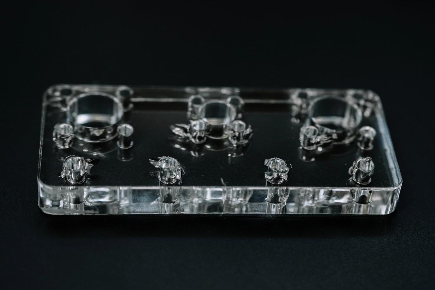
Acrylic machined part - Depositphotos
Selecting a plastic for CNC machining involves comparing strength values, impact performance, optical properties, environmental exposure, edge quality, and fabrication requirements.
| Property / Behavior | Polycarbonate (PC) | Acrylic (PMMA) | Acetal (POM) | Nylon (PA) | ABS |
|---|---|---|---|---|---|
| Machining response | Cuts easily, heat-sensitive edges | Clean cut, but brittle | Stable cutting, consistent chips | Flexible, can deform slightly | Easy to machine, moderate finish |
| Edge condition | May whiten if heat builds | Sharp, clear finish | Clean and stable edges | Slight fuzz on edges | Generally clean edges |
| Crack risk during machining | Low impact cracking resistance | High edge cracking risk | Low cracking tendency | Low cracking, but flexible | Medium under stress |
| Dimensional behavior | Stable if heat is controlled | Stable but brittle under load | Very stable | Changes with moisture | Stable for general parts |
| Tool behavior impact | Needs sharp tools to avoid marks | Needs light cutting to avoid chipping | Supports aggressive cutting | Requires controlled feed | Balanced machining behavior |
| Typical CNC use | Guards, covers, transparent parts | Optical parts, display panels | Precision mechanical parts | Bushings, wear parts | Enclosures, housings |
Material Properties That Influence Machining Performance
Polycarbonate behaves differently from metals during CNC machining. It usually reacts more to heat, cutting pressure, and tool contact. Here are the typical factors that directly affect surface finish, dimensional accuracy, and part appearance.
Impact Resistance and Toughness
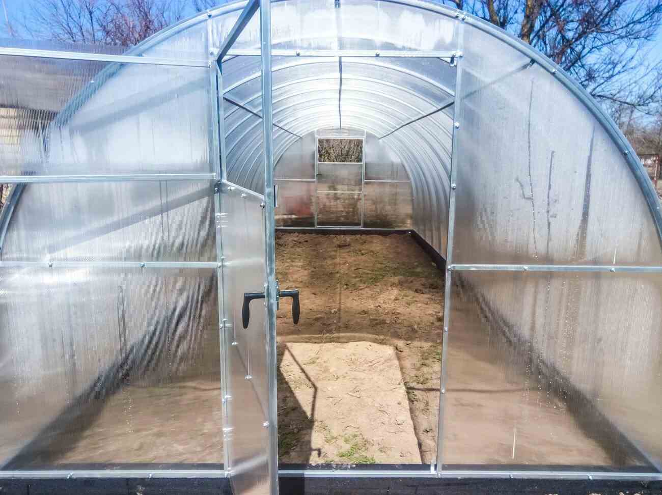
Polycarbonate greenhouse assembled from parts - Alamy
- Polycarbonate does not crack easily. Thus, it is used for guards, covers, and housings that face handling or impact.
- Moreover, it keeps stability around holes and thin sections during machining.
Transparency and Surface Appearance
- Clear PC grades are used for windows and inspection parts where surface marks are visible.
- Tool sharpness and cutting conditions directly decide surface quality.
Heat Response During Cutting
- Polycarbonate softens when heat builds up at the cutting zone.
- Poor cutting conditions cause whitening, drag marks, or slight melting.
Moisture and Dimensional Stability
- Polycarbonate absorbs less moisture than nylon and many engineering plastics, helping maintain dimensional stability in typical environments.
- Final inspection is still needed for tight-tolerance parts after machining.
CNC Processes Used for Polycarbonate Parts
Polycarbonate is machined using standard CNC processes like milling, turning, drilling, and cutting. The process depends on the part shape, thickness, and which surfaces will be visible in the final use.
CNC Milling for Complex Features
Milling is used for parts with pockets, slots, contours, and mixed-surface geometry. It is the most common process for polycarbonate housings, covers, and functional parts. Tool sharpness and stable cutting are important because visible surfaces can easily show marks if cutting conditions are not controlled.
CNC Turning for Round Parts
Turning is used for cylindrical components such as rings, spacers, bushings, and round housings. The material rotates while the tool removes material from the inner or outer diameter. This process is chosen when the part needs accurate diameter control and symmetry.
Drilling and Threading
Drilling is used for fastener holes, alignment features, and assembly points. Threads are created either by tapping or CNC thread milling, depending on depth and design. Clean entry and exit help reduce cracking or stress around hole edges.
Polycarbonate CNC Cutting and Profiling
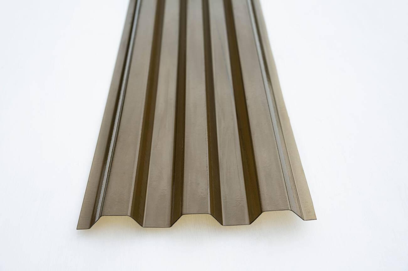
Polycarbonate plastic trapeze for roofing - Alamy
Sheet and block materials are often pre-cut before final machining. For flat guards, windows, and panel components, polycarbonate CNC cutting is commonly used to create external profiles before secondary drilling or milling operations are performed. This includes rough profiling and contour cutting to separate parts from stock. Tool selection and cutting control are important because edges may remain visible in the final product and may need minimal finishing.
Polycarbonate parts vary significantly in thickness, transparency requirements, and machining complexity. Upload your CAD file to verify manufacturability, tolerances, and lead time before production.

Precision CNC Machining Service
Professional manufacturing, fast turnaround, and quality assurance.
Designing Polycarbonate Parts for CNC Machining
Polycarbonate part design has a direct link with how the material behaves during machining. Geometry decisions influence tool movement, surface condition, dimensional control, and visible appearance. Small changes in design often reduce machining steps and improve part consistency during production.
Wall Thickness and Structural Support
Wall thickness affects how stable the material stays during cutting. Thin sections below 1.5 mm can flex under tool contact, especially in larger flat areas. A safer range for most machined enclosures stays around 2 mm to 4 mm, depending on part size. Thicker sections support better surface quality but increase material removal time.
Internal Corners and Tool Accessibility
Internal corners cannot be perfectly sharp due to tool geometry. A corner radius equal to the cutter size, often 1 mm to 3 mm in CNC setups, is commonly used. If the design allows larger radii, tool movement becomes smoother and reduces edge marking inside pockets and recesses.
Hole Design and Threaded Features
Hole sizes below 2 mm increase tool sensitivity and require careful drilling control to avoid edge stress. For threaded holes, designers often prefer heat-set inserts or tapped threads above M3 size for better thread strength in polycarbonate. Proper chamfering helps reduce cracking around entry points during assembly.
Design Considerations for Transparent Components
- Transparent polycarbonate shows machining marks more clearly than opaque plastics.
- Flat optical faces should avoid deep step-over tool marks because they reduce clarity and create visible lines on the surface.
- Large viewing windows are usually finished with fine passes and controlled step-over values around 0.1 mm to 0.3 mm to keep the surface visually clear.
Tolerances and Surface Finish in Polycarbonate Machining
Polycarbonate holds its size well when set up, and cutting conditions stay stable. In production, geometry and tool access affect tolerance more than the material itself.
Typical CNC Machining Tolerances
- Standard parts usually stay within ±0.05 mm to ±0.10 mm in normal production runs.
- In highly controlled machining environments, selected critical features may achieve tolerances approaching ±0.02 mm, depending on geometry, material thickness, and machining conditions.
- Deep and internal features vary more due to tool deflection and limited tool access.
Surface Roughness After Machining
Standard milling on polycarbonate produces surface roughness around Ra 1.6 to 3.2 µm. Fine finishing passes with reduced step-over can improve the surface to around Ra 0.8 µm. Deep pockets and internal grooves often show higher roughness because chip evacuation becomes restricted during cutting.
Polishing and Optical Finishing
- Transparent polycarbonate shows tool marks clearly, so machining alone is not enough for optical surfaces.
- Parts like viewing windows may be finished using vapor polishing, mechanical polishing, or other controlled optical-finishing methods to improve clarity after machining.
- A light post-processing polish helps reduce visible tool paths and improves transparency on finished surfaces.
Edge Quality and Transparency Requirements
- Machined edges can hold stress, so sharp corners are usually deburred or lightly chamfered.
- Transparent parts need smooth edge transitions to avoid whitening and improve visual clarity.
- Cleaner edges also reduce crack initiation points in handled or assembled components.
Common Challenges in Polycarbonate Machining
Polycarbonate machining depends heavily on cutting conditions because the material reacts quickly to heat, tool contact, and pressure at the cutting zone. Most of the surface issues appear on edges, clear faces, and thin sections where tool support and heat control are limited.
Heat Buildup and Material Smearing
Heat builds up at the cutting edge when feed rate and tool sharpness are not balanced. Instead of clean chip removal, the material can soften and smear along the surface. This shows up as cloudy marks or dragged lines, especially on shallow finishing passes.
Stress Cracking and Edge Chipping
Sharp internal corners and drilled holes can develop small cracks if the tool entry pressure is too high. Chipping often appears around fastener holes and cut transitions. Adding small chamfers and using controlled entry feeds helps reduce these defects during machining.
Burr Formation During Cutting
Burrs form along edges when the material stretches instead of breaking cleanly at the tool exit. This is common in thin walls and slot features. Secondary deburring steps are usually required to clean edge conditions before assembly or finishing.
Maintaining Optical Clarity During Processing
Transparent polycarbonate parts can lose clarity if machining marks remain visible on exposed surfaces. Tool marks, uneven finishing passes, and heat-affected zones reduce visual quality. Controlled finishing passes and consistent tool condition help maintain a clearer surface appearance after machining.
Cost Factors in Polycarbonate CNC Machining
Cost in polycarbonate machining comes from measurable production elements such as stock preparation, cycle time, tool engagement, and post-machining finishing steps. Each step adds time to the machine or manual handling after cutting.
Material Utilization and Stock Size
Cost changes when the part layout does not match standard sheet or block sizes. Flat parts cut from sheet stock usually reduce waste because multiple profiles can be nested. Block machining increases cost when large portions of material are removed to reach the final geometry, especially for 3D housings and deep cavities.
Machining Time and Feature Complexity
Cycle time increases when tool paths include deep pockets, narrow slots, or internal features. Internal geometry requires smaller tools and slower cutting passes to maintain stable chip removal. Simple profiles with through holes and open surfaces complete faster because tool movement stays direct and uninterrupted.
Finishing and Transparency Requirements
Clear polycarbonate parts often need extra surface work after machining. Tool marks remain visible on exposed faces, so finishing passes or polishing steps are added. Parts used as guards, windows, or covers usually include edge cleanup and surface smoothing, which increases handling time after CNC operations.
Prototype vs Production Quantities
Single parts carry a higher cost because setup, tool setup, and programming time apply to one piece only. Small batches spread setup time across multiple parts, reducing per-unit cost. Larger production runs reduce cost further when the same fixture and toolpath are reused without changes.
Cost Comparison Overview
| Cost Factor | Lower Cost Level ($) | Moderate Cost Level ($$) | Higher Cost Level ($$$) |
|---|---|---|---|
| Material Utilization | Parts nested from standard sheet size | Mixed sheet and block usage | Large billet removal for 3D geometry |
| Machining Time | Simple profiles, through holes | Moderate pockets and slots | Deep cavities and internal features |
| Finishing Work | Basic deburring only | Light edge smoothing | Surface polishing for clear parts |
| Batch Quantity | Repeated production batches | Small batch runs | Single prototype or one-off part |
| Setup and Tooling | No tool change during run | Limited tool changes | Multiple tool changes and special cutters |
Common Applications of CNC-Machined Polycarbonate Parts
Polycarbonate parts are used when a component needs visibility through the part and needs to survive impact during handling or operation. CNC machining supports these parts because geometry changes can be applied directly without tooling changes.
Transparent Covers and Machine Guards
Machine guards and protective covers use polycarbonate because operators can see inside the equipment while keeping their hands away from moving parts. CNC machining creates mounting holes, cutouts, and edge profiles for frames and hinges. Parts are commonly used on CNC machines, automation lines, and inspection stations where visibility and protection stay together in one panel.
Medical and Laboratory Components
Laboratory trays, test fixtures, and instrument housings use polycarbonate for repeated cleaning and handling. CNC machining allows accurate pocket depths and alignment features for instruments and cartridges. These parts are often designed with smooth internal corners to support cleaning and reduce particle retention during use.
Electrical and Electronic Enclosures
Control panels, sensor housings, and protective covers for electronic systems use polycarbonate because it supports insulation and allows visual monitoring of internal components. CNC machining is used to produce cutouts for connectors, switches, and display windows with consistent positioning across assemblies.
Industrial Equipment Components
Industrial systems use polycarbonate for inspection windows, protective shields, and alignment covers. These parts allow operators to check internal movement or fluid flow without opening the system. CNC machining supports these parts by matching enclosure geometry and adding precise mounting features for secure installation.
When to Choose CNC Machining for Polycarbonate Parts
Polycarbonate parts can be produced through CNC machining, injection molding, or sheet-based fabrication. These processes represent different approaches within polycarbonate manufacturing, each suited to different production volumes, tooling requirements, and design constraints. The choice usually depends on volume, geometry stability, and how early the design is finalized.
CNC machining remains common when parts are still under development or when geometry changes are expected. It also fits well when internal features, pockets, and multi-surface shapes cannot be formed with flat sheet processing.
Injection molding shifts the cost balance in large-scale production. Once the design is locked, mold-based production reduces per-part cost significantly, especially when thousands of identical parts are required.
Sheet processing works in a different direction. It is used when the part is mostly flat, with limited depth features and simple cut profiles. In such cases, CNC milling of full 3D geometry becomes unnecessary.
When CNC Machining Is the Best Choice
- Design is still under revision or in the prototype stage
- Internal pockets, stepped features, or 3D geometry are required
- The batch size is small to medium and does not justify tooling investment
- A short lead time is required without waiting for mold creation
- Different polycarbonate grades need testing in the same design
- Dimensional adjustments are expected during early production runs
When Injection Molding Becomes More Economical
- Production volume is high, and repeated batches are planned
- Part design is finalized with no expected changes
- Unit cost reduction is critical at scale
- Consistent cycle time is required across large production runs
- Geometry is stable enough to justify the mold cost and setup time
| Factor | CNC Machining | Injection Molding |
|---|---|---|
| Production volume | Suitable for low to medium runs | Efficient for high-volume production |
| Setup requirement | No dedicated tooling needed | Requires mold fabrication |
| Design changes | Can be updated quickly | Changes require mold modification |
| Lead time | Faster start for production | Longer initial preparation |
| Cost behavior | Stable per part | Drops significantly at scale |
When Sheet Processing Methods Are More Suitable
- Parts are flat with 2D profiles and minimal depth features
- Large panels, guards, or covers are required
- Cost priority is higher than 3D geometry complexity
- Thickness remains uniform across the part
- Edge finishing is acceptable without complex machining steps
How to Choose a Polycarbonate CNC Machining Service
Selecting a CNC machining supplier for polycarbonate parts depends on how well the shop handles plastic behavior during cutting, not only machine availability. Engineers usually evaluate process control, finishing capability, and consistency across batches.
Experience With Engineering Plastics
A supplier familiar with engineering plastics understands how polycarbonate reacts during cutting. This includes managing heat marks, edge whitening, and surface drag on transparent parts. Experience shows in how the shop handles tool selection, cutting speed control, and edge finishing without damaging the appearance.
Machining Capability and Tolerance Control
Machining capability is judged by how stable the dimensions stay across repeated runs. For polycarbonate parts, this includes control of hole sizes, pocket depth, and mating features. Shops with stable fixtures and controlled tool paths usually produce more consistent results, especially on internal or thin-walled features.
Surface Finishing and Optical Requirements
Many polycarbonate parts require visible surfaces, so finishing quality becomes important. A capable supplier can manage deburring, edge smoothing, and polishing when required. For transparent parts, control of tool marks and surface consistency affects final appearance more than dimensional accuracy alone.
Prototype-to-Production Support
A reliable machining service supports both early prototypes and later production runs using the same process logic. This helps maintain design consistency when moving from sample parts to batch production. It also reduces variation in fit and appearance when quantities increase over time.
Conclusion About Polycarbonate CNC Machining
Polycarbonate CNC machining supports parts that need clarity, impact resistance, and stable dimensional control. The process works well for complex geometry, but final quality depends on heat control, tool condition, and part design choices made before machining starts.
In production, surface condition often needs more attention than the cutting itself. Tool marks, edge whitening, and localized heat effects can appear on visible surfaces if parameters are not controlled. Geometry decisions such as wall thickness, corner radius, and hole placement directly influence machining stability and finishing effort.
CNC machining remains suitable for prototypes, custom parts, and low- to medium-volume production. It also supports fast design updates without waiting for tooling changes, which helps during development and validation stages.
JLCCNC provides CNC machining services for polycarbonate and other engineering plastics, supporting both prototypes and production parts. The team reviews design files for manufacturability, offers guidance on feature feasibility, and supports consistent production from sample to batch orders. Quotes are typically fast, with machining options tailored to geometry, tolerance, and finishing needs.
Precision CNC Machining Service
Professional manufacturing, fast turnaround, and quality assurance.
FAQ About Polycarbonate CNC Machining
Q: Is polycarbonate easy to machine?
Polycarbonate cuts without high cutting force, so machining feels smooth during operation. The main control point is heat. If heat builds up, edges can show whitening or surface drag.
Q: Can polycarbonate be CNC cut?
Yes, CNC cutting works well for polycarbonate sheets, blocks, and rods. It is commonly used for profiles, covers, and structural parts with holes, pockets, and cutouts.
Q: What tolerances can be achieved in polycarbonate machining?
Standard CNC setups hold around ±0.05 mm to ±0.10 mm on most features. Stable setups with short tool reach can reach tighter control near ±0.02 mm on simpler geometries.
Q: Does CNC machining affect polycarbonate transparency?
Yes, tool marks and heat zones can reduce clarity on visible surfaces. Finer finishing passes and sharp tools help keep surfaces clearer after machining.
Q: Can threads be machined into polycarbonate?
Yes, but performance depends on size and load. Small threads can wear out over repeated use, so inserts are often used when stronger fastening is needed.
Q: Is polycarbonate better than acrylic for CNC machining?
Polycarbonate handles impact better and resists cracking during machining. Acrylic gives a clearer optical finish but can chip or crack more easily around edges and holes.
Q: When should CNC machining be used instead of injection molding?
CNC machining is considered a better option when quantities are low, design changes are still expected, and complex geometry is required. While injection molding is more efficient when production volume is high, the design is fixed.
Keep Learning
Polycarbonate CNC Machining: Properties, Design Guidelines, and Manufacturing Considerations
Key Takeaways About Polycarbonate CNC Machining Polycarbonate is used for clear guards, covers, housings, and inspection parts where visibility and protection matter in use, not just on drawings. Different machining materials or grades behave differently during cutting and show up mainly in surface clarity and edge condition. Heat from cutting affects surface marks more than the strength of the material itself. Thin walls and wide flat areas are where most surface issues start during machining. Tool s......
Polycarbonate vs Acrylic for CNC Parts: Strength, Machining & Material Selection
Quick Comparison: Polycarbonate vs Acrylic Property Polycarbonate Acrylic Tensile strength 55–75 MPa 70–80 MPa Impact resistance 600–900 J/m (notched Izod) 15–30 J/m Flexural modulus 2.1–2.5 GPa 3.0–3.3 GPa Light transmission 88–90% 92–93% Heat deflection temp approximately 110–130°C depending on grade and test condition 75–100°C Chemical resistance Moderate. attacked by solvents Good. resists most common chemicals Machinability Good. tends to melt at edges Excellent. clean chips, sharp edges UV resis......
What Is Bakelite? Properties, Manufacturing Process, and CNC Machining Guide
(AI generated) Vintage bakelite switch and modern machined bakelite Bakelite still appears in electrical systems, legacy equipment, and industrial fixtures where thermal stability and insulation matter more than mechanical toughness. In these environments, materials are not selected for flexibility or impact resistance, but for their ability to remain stable under heat, voltage, and long-term load. Unlike modern thermoplastics, Bakelite does not soften or deform once formed. That behavior affects not ......
Thermoset vs Thermoplastic: Key Differences, Properties, and Manufacturing Applications
Thermosets and thermoplastics are the two main types of plastics used in manufacturing. Choosing between thermoset vs thermoplastic materials significantly affects CNC machining performance. On paper, they can appear similar. In practice, they behave very differently when exposed to heat, mechanical stress, or cutting forces. This difference shows up quickly in real projects. It affects: ● Heat resistance and softening behavior ● Long-term deformation under load ● CNC machining stability and tool wear......
Plastic CNC Machining: Guide to Materials, Machines & Cutting Strategies
Understanding Plastic CNC Machining When most people think of CNC machining, metals come to mind first, aluminum, steel, titanium. But plastic CNC machining has quietly creeped into many industries. Why? Because plastics are lightweight, versatile, and cost-effective, making them an ideal option for places where the best performance is needed on the best budget. CNC for plastic is now as common as CNC for metal. At JLCCNC, we don't just work with metals, we also provide CNC machining of plastic parts ......
ABS vs Polycarbonate: Which Plastic Is Better for CNC Machining?
● Choose ABS for lower cost, faster machining, and stable tolerances (non-transparent parts). ● Choose PC for impact resistance and transparency, but expect higher machining risk and cost. ● For thin walls + tight tolerances, ABS is usually safer. ● For clear guards/windows, PC is the only practical option (often needs polishing). This guide compares ABS and polycarbonate specifically from a CNC machining perspective, helping engineers select the right plastic based on machining behavior, tolerance ri......