Profile of a Surface in GD&T: Symbols, Tolerances & Examples
12 min
- What Is Profile of a Surface?
- Profile of a Surface Symbol and Feature Control Frames
- How Profile of a Surface Works
- Profile of a Surface vs Other GD&T Controls
- When Should You Use Surface Profile?
- Typical Applications of Surface Profile Tolerance
- Specifying Profile Tolerance on Engineering Drawings
- Measuring Profile of a Surface
- Practical Profile Tolerance Examples
- Common Profile Tolerance Mistakes
- FAQs About Profile of a Surface
Key Takeaways
- A profile tolerance controls the form of a surface and may also control its orientation and location when datum references are specified.
- The surface symbol identifies a three-dimensional geometric control.
- Basic dimensions establish the intended contour.
- Datum references can orient and locate the controlled area.
- Inspection evaluates the manufactured surface against its nominal geometry.
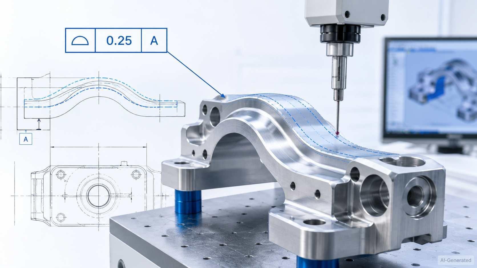
CMM inspecting surface profile on a machined part
Knowing the profile of surface requirements allows engineers to define complicated geometry through one coordinated GD&T callout, linking design intent with production and verification.
What Is Profile of a Surface?
In GD&T, profile of surface defines a three-dimensional tolerance zone around a theoretically exact contour. It limits how far the manufactured geometry may differ from its intended shape.
What Does Surface Profile Control?
Depending on its datum references, profile tolerance can govern form alone or also control a surface's orientation and location. This control is useful for curved, blended, or irregular features.
Profile of a Surface Symbol and Feature Control Frames
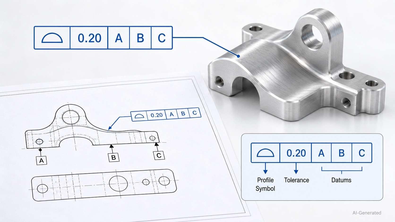
Surface profile symbol and feature control frame diagram
Profile of a Surface Symbol
The profile of a surface symbol consists of a semicircular arc connected to a straight line inside the feature control frame. The profile symbol is defined in ASME Y14.5 standards, including ASME Y14.5-2018, which establishes rules for geometric dimensioning and tolerancing on engineering drawings. In GD&T practice, profile tolerance may control surface form alone or additionally control orientation and location when datum references are specified.
International drawings may also follow ISO GPS standards such as ISO 1101, depending on regional or customer requirements.
Feature Control Frame
The feature control frame presents the geometric symbol, tolerance value, and any required datum references. Datum references are added when the surface must be controlled relative to a specific reference system. Datum references are added when the surface must be controlled relative to a reference system. They establish how the controlled geometry must relate to the rest of the part.
How to Read a Profile Tolerance Callout
Read the callout from left to right:
- identify the control
- note the tolerance value
- review each datum in its listed order.
This sequence shows the profile tolerance requirement and the datum reference system used during inspection. A callout may contain three datum levels: primary, secondary, and tertiary.
How Profile of a Surface Works
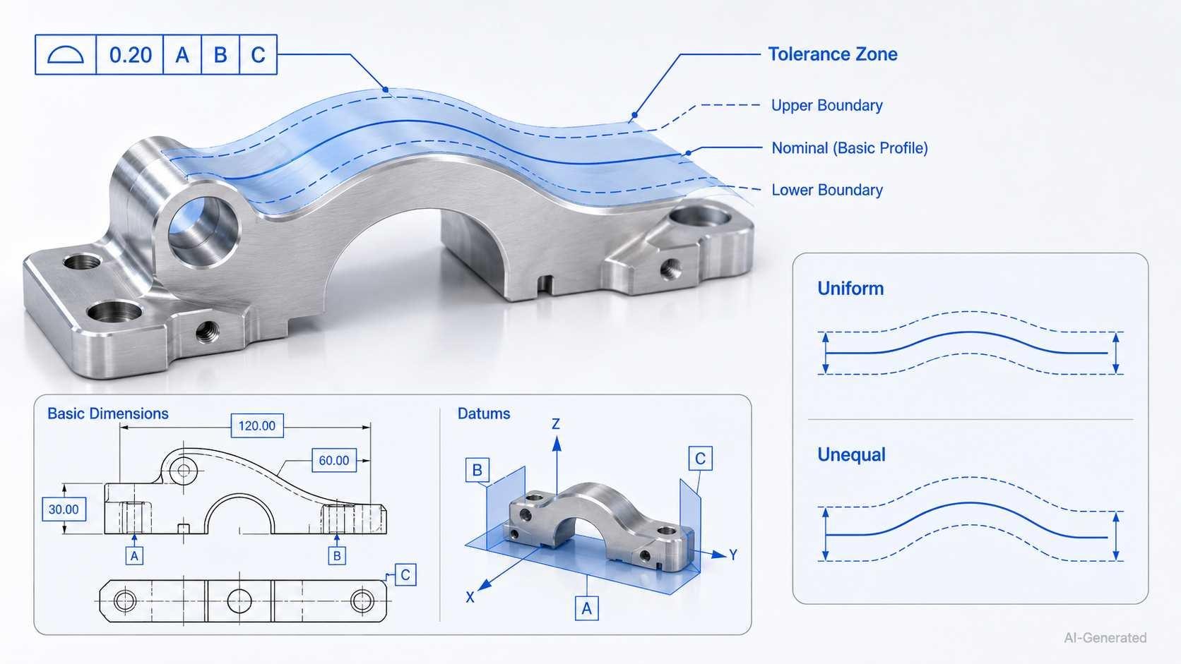
Surface profile tolerance zone with datums and dimensions
Tolerance Zone
A GD&T profile tolerance creates a three-dimensional zone between two boundaries that follow the exact contour. A 0.20 mm equally disposed zone allows 0.10 mm on each side of the true profile. Every point on the controlled surface must be within those limits. Unless otherwise specified, the tolerance zone is equally disposed about the true profile.
Basic Dimensions
Boxed basic dimensions establish the theoretically exact size, shape, and placement of that contour. They provide the nominal geometry from which inspectors evaluate surface deviation. A boxed 25.00 mm basic dimension is theoretically exact; variation is governed elsewhere.
Datum References
When datums appear in the callout, they anchor the zone to a datum reference frame and govern its orientation or location. A conventional 3-2-1 datum setup can restrain all six rigid-body degrees of freedom. In a conventional 3-2-1 datum setup, three primary contact points establish the primary plane, two secondary points orient the part in the second direction, and one tertiary point completes the six-degree-of-freedom constraint. Without them, the GD&T profile tolerance may control form alone.
Uniform and Unequal Profile Tolerance
A uniform zone maintains the stated width around the contour. An unequal-disposition modifier shifts the tolerance zone toward one side while keeping the total tolerance value unchanged. A 0.60 mm callout with Ⓤ 0.20 places 0.20 mm outward and 0.40 mm inward.
Profile tolerance requirements can affect machining strategy, inspection methods, and manufacturing feasibility. JLCCNC reviews GD&T drawings during the engineering review stage to identify potential production challenges before machining begins.

Precision CNC Machining Service
Upload your CAD model and drawing to receive a manufacturability review and CNC machining quote for your part.
Profile of a Surface vs Other GD&T Controls
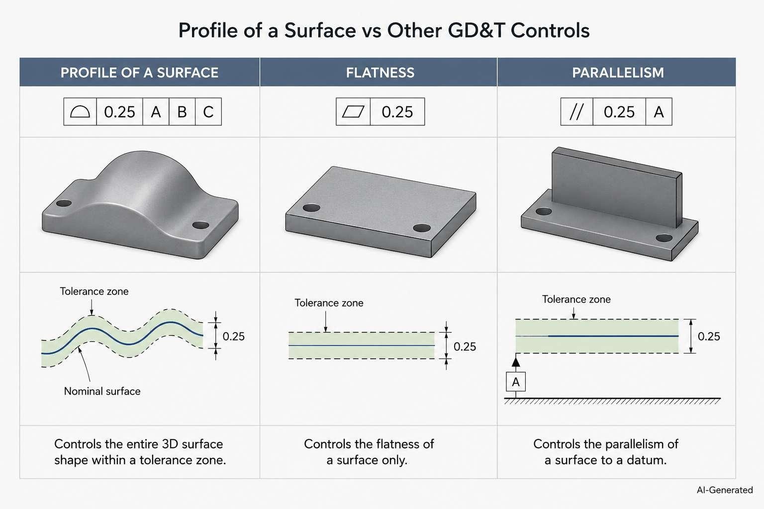
Surface profile compared with flatness and parallelism
Profile of a Surface vs Profile of a Line
Profile of a line evaluates each specified cross-section. On the other hand, a surface profile tolerance evaluates the full three-dimensional surface. Choose line profile for section-by-section control and surface profile when the entire contour must remain coordinated.
Profile of a Surface vs Flatness
GD&T flatness only controls the form of a nominally planar surface. It does not determine the orientation or location of the feature. Moreover, it is a good option for a mating plane. Choose a surface profile for curved geometry or a surface tied to datums.
Profile of a Surface vs Position
Position locates the axis or median plane of a feature of size, such as a hole or slot. Use it for feature centers. Surface profile tolerance is better when the boundary itself drives function.
When Should You Use Surface Profile?
When Form and Location Must Be Controlled Together
You should make use of the profile surface symbol whenever a functional boundary must maintain its shape as well as remain correctly oriented and located from selected datums. One callout can coordinate these requirements across the governed surface.
When Complex or Freeform Surfaces Are Critical
For sculpted blades, blended transitions, molded shells, or other freeform geometry, the profile surface symbol follows the nominal contour more effectively than several separate controls. Engineers pick it when the boundary affects assembly, sealing, flow, or performance.
When Simpler GD&T Controls Are Sufficient
Remember, you should use flatness, straightness, position, or an orientation control when only one geometric requirement is important. The most appropriate selection is the least restrictive control that protects function and supports economical production.
Typical Applications of Surface Profile Tolerance
Complex CNC Machined Surfaces
The profile of surface requirement works well for contoured pockets, turbine blades, impellers, and blended faces produced through precision CNC machining. This applies when deviation across the entire machined boundary affects part performance. It captures complex geometry that individual form controls may not coordinate effectively.
Cast and Forged Parts
Castings and forgings contain draft angles, radii, and flowing transitions that might be created by tooling. Meanwhile, surface profile allows engineers to limit these connected features through one functional specification, rather than many isolated dimensions.
Molded Components
Plastic housings, seals, and ergonomic shells may include curved walls, ribs, and mating edges. A profile tolerance can protect critical mating interfaces while allowing variation in less functional areas.
Aerospace and Medical Parts
Aerospace airfoils and patient-specific implants typically depend on complicated geometry for flow, contact, or anatomical alignment. At the same time, the surface profile provides one coordinated way to specify and inspect those functional boundaries.
Specifying Profile Tolerance on Engineering Drawings
Selecting Datum References
Choose datum features that highlight how the part is assembled, supported, and inspected. Their sequence should restrain only the movements that are critical to function.
Choosing Appropriate Tolerance Values
Set the value from functional limits, production capability, and measurement needs. Allowing reasonable variation can reduce machining and verification demands and maintain performance.
Applying Profile to Functional Surfaces
It is necessary to apply the profile of surface to boundaries whose contours have an impact on sealing, contact, airflow, appearance, or assembly functions. In situations when the remaining geometry is less important, restrict the callout to the relevant region.
Avoiding Over-Tolerancing
Do not assign narrow limits to every surface by default. Separate critical regions from noncritical ones. After that, permit wider variation wherever product performance allows it.
Measuring Profile of a Surface
Coordinate Measuring Machines (CMM)
A CMM will use a probe to collect points during a profile of surface inspection, and then it will compare the coordinates of those points with the nominal CAD geometry on the surface. Both intricate contours and datum-based evaluations can be accomplished with this method.
Optical Measurement Systems
Laser scanners and optical profilometers capture surface data without physical contact. They are valuable for delicate components, broad areas, and features that a touch probe cannot reach.
Functional Inspection Methods
Dedicated gauges or mating fixtures provide an acceptance check under assembly-like conditions. This approach is helpful when production teams need a direct pass-or-fail decision.
Inspection Reports
The report records datum alignment, sampled locations, measured deviations, and the profile tolerance result. Consistent reporting also supports traceability and manufacturing feedback.
Practical Profile Tolerance Examples
CNC Machined Surface
A contoured housing face may have a profile of surface callout of 0.20 mm to datums A, B, and C according to the specifications and required CNC machining tolerances. While the machinist follows the basic dimensions, a CMM does a comparison between the measured points and the nominal CAD model.
Cast Component
A pump casing may receive a 1.0 mm profile tolerance across its outer wall. This may allow suitable casting variation as well as protect flange and passage geometry. Inspectors can scan the part and review whether or not the captured surface is within the specified boundaries.
Freeform Surface
An airfoil blade may use a 0.10 mm callout over a region to govern its aerodynamic contour. Dense optical scan data can expose local high/low areas that sparse point checks may overlook.
CNC Machined Aluminum Housing Example
An aluminum housing with a complex contoured surface may require a 0.05 mm profile tolerance relative to datum references A, B, and C. To maintain the relationship between the machined surface and datum features, the part may require a stable fixture setup and coordinated CNC machining strategy. After machining, a CMM inspection compares the measured surface against the nominal CAD model to verify compliance.
Common Profile Tolerance Mistakes
Omitting Basic Dimensions
- Without basic dimensions, the nominal contour or location may not be fully defined. This would leave the production and inspection teams without a specified foundation for assessment. The drawing might have to be revised before the work can begin.
Incorrect Datum References
- The part can be restrained in a manner that is not consistent with its assembly configuration, which may result in acceptable parts failing inspection or defective parts passing inspection. The datum order should match the functional contact and the degrees of freedom that are planned.
Applying Profile Where Simpler Controls Are Sufficient
- When a need is satisfied by flatness, perpendicularity, or position, using profile might add complexity to the drawing and increase the amount of work required for inspection. Choose the control that is the least restrictive while yet protecting the function that is desired.
Using Excessively Tight Profile Tolerances
- Machining effort, scrap risk, inspection demands, and production costs might rise when the limitations are narrower than what is functionally necessary. Establish acceptability limits based on the requirements of the assembly and the capable production methods.
FAQs About Profile of a Surface
Q: What Is Profile of a Surface?
Profile of a surface is a GD&T control that limits variation across an entire 3D contour.
Q: What Is Surface Profile Tolerance?
The entire width that is permissible between two boundaries is referred to as the surface profile tolerance. It is derived from the geometry that is theoretically accurate.
Q: What Does the Profile of a Surface Symbol Mean?
The profile of a surface symbol indicates that the controlled surface must remain within the specified profile tolerance zone shown in the feature control frame.
Q: How Is Profile Tolerance Measured?
A coordinate measuring machine, scanner, or optical system captures surface data and then compares that data with the nominal model under the required alignment.
Q: Does Profile Tolerance Require Datums?
No. Without datums, it can govern form. They may add orientation and location requirements.
Q: What Is the Difference Between Profile of a Line and Profile of a Surface?
Line profile evaluates selected two-dimensional sections. In comparison to this, the surface profile is implemented across the complete three-dimensional area.
Q: What Is the Difference Between Profile Tolerance and Flatness?
The form of a planar feature is the sole thing that can be governed by flatness. On the other hand, profile may influence curved geometry and its connection to datums.
Q: When Should Profile of a Surface Be Used?
It is utilized in situations when a shaped boundary, blended contour, or connected group of surfaces is required to fulfill a single coordinated geometric requirement.
Q: Can profile tolerance control location?
Yes. When datum references are included, profile tolerance can control the orientation and location of a surface relative to the datum reference frame.
Precision CNC Machining Service
If your drawing includes profile tolerance requirements, JLCCNC can review the GD&T callouts and machining approach before production. Upload your CAD model and drawing to request an engineering review and quote.
Conclusion About Profile of a Surface
Profile of a surface provides a way to define complex contours with controlled variation from the theoretically exact geometry. It is especially useful when a part relies on curved surfaces or blended transitions that cannot be fully described by individual dimensional controls.
In CNC machining, profile tolerance requirements need to be considered during manufacturing planning because the specified contour affects how the part is machined and inspected. JLCCNC reviews GD&T requirements before production to evaluate manufacturability and determine a suitable machining approach.
Keep Learning
Laser Engraving Aluminum: Marking Methods & Surface Effects
Key Takeaways Laser engraving usually removes base material to create a recess. Laser marking is a broader term that can describe a surface-color change or material removal, so the process name alone does not define the final result. On aluminum, alloy and surface finish affect marking contrast. A light mark on dark anodized aluminum is a common design target, but the actual appearance depends on the finish and laser process. JLCCNC laser marking produces a recessed area 0.03–0.1 mm deep. The result i......
CNC Cutting Fluid: Types, Functions, Applications, and Selection Guide
Key Takeaways Cutting fluid in machining performs four functions simultaneously: cooling the tool and workpiece, lubricating the tool-chip interface to reduce friction, carrying chips away from the cut zone, and protecting machined surfaces from corrosion between operations. Different machining operations need different fluid priorities: high-speed aluminum milling may need adhesion control and chip evacuation, threading and tapping need strong lubrication, and grinding requires both cooling and fine ......
Blind Hole Machining Guide: What Is a Blind Hole, Types of Holes, and Tapping Tips
What Is a Blind Hole? Types of Holes and CNC Hole Machining Explained In CNC machining, few operations challenge process control and tool stability as much as blind hole machining. A blind hole is a hole that terminates at a defined internal depth rather than breaking through the opposite surface. Because the cavity is enclosed at the bottom, chip evacuation, thermal behavior, tool wear, and dimensional accuracy become far more difficult to manage compared to through-hole machining. These constraints ......
Rake Angle in Machining: Machinists’ Guide to Perfect Cuts
What is Rake Angle? (minaprem) If you've ever stood in front of a CNC machine or a manual lathe, you know that the cutting tool's geometry isn't just some arbitrary design. Every angle, edge, and surface has a job to do, and one of the most important of those is the rake angle. We've been running machines long enough to know that rake angle can make or break your surface finish, tool life, and machining efficiency. In this guide, we're going to walk you through what rake angle is, how it works, and ho......
Sheet Metal vs CNC Machining: A Guide to Choosing the Right Method for Your Metal Parts
Quick Answer: Choose sheet metal for uniform-thickness enclosures, panels, and formed brackets when bends and production volume support lower unit cost. Choose CNC machining for variable wall thickness, precision bores, tight feature relationships, and complex 3D geometry. Use a hybrid design when a formed structure needs precision-machined interfaces. A quote comes back for a bracket, and it's priced as a CNC part — machined from solid aluminum, a few hours of spindle time, a per-part cost that makes......
What Steps Are Taken To Minimize Waste In CNC Machining Processes?
How to Reduce Waste in CNC Machining: 5 Practical Strategies Quick Answer: CNC machining waste is reduced mainly through DFM, near-net stock, efficient toolpaths, preventive tool maintenance, and alloy-segregated recycling. The biggest gains usually come before cutting: reduce unnecessary material removal and prevent scrap or rework. Every CNC-machined part starts as more material than it ends up being. A pocket gets milled out, a profile gets cut away, a boss gets faced down to size — and all of that......