Anodizing Thickness: How Much Does It Add?
10 min
- What Does Anodizing Thickness Mean
- How Much Does Anodizing Change Part Dimensions
- Type II Anodizing Thickness Range
- How Anodizing Affects CNC Critical Dimensions
- How to Specify Anodizing on a CNC Drawing
- Conclusion: Anodizing Thickness and Dimensional Control
Anodizing Thickness and Dimensional Change at a Glance
| Feature | Approximate dimensional effect |
|---|---|
| One coated external surface | +0.5 × coating thickness |
| Outside diameter across two coated surfaces | +1 × coating thickness |
| Bore diameter with two coated walls | −1 × coating thickness |
| 60° thread pitch diameter | Changes by about 4 × surface-growth amount, or about 2 × coating thickness under the 0.5× growth assumption |
Dimensional estimates below use the 0.5 × coating-thickness surface-growth relationship given in MIL-PRF-8625F for design purposes. Actual growth can vary with anodizing process, alloy, and part geometry.
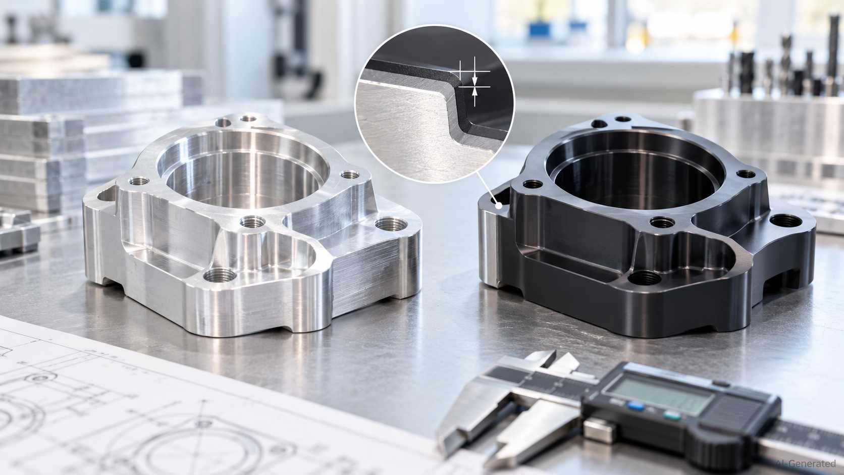
Anodized and raw CNC parts with coating thickness inset
A CNC-machined aluminum part can meet its machining tolerances before finishing and still fall out of tolerance after anodizing. But anodizing can change what inspection finds afterward. The process forms aluminum oxide from the metal surface. It creates a coating whose growth must be considered during dimensional planning. When engineers understand anodizing thickness, they account for that change when specifying machined features, tolerances, coating requirements, and final inspection criteria.
For CNC aluminum parts, JLCCNC uses different typical coating thicknesses depending on the anodizing finish. Natural-color anodizing is around 0.008 mm, while other anodizing colors are around 0.015 mm. Hard coat anodizing is typically around 0.025–0.030 mm, and conductive anodizing is around 0.003 mm. These are typical values for planning; the required finish and thickness should be confirmed for the specific part and drawing.
Upload your CAD files to get an instant CNC machining quote and DFM feedback from JLCCNC engineers.

Precision CNC Machining Service
Professional manufacturing, fast turnaround, and quality assurance.
What Does Anodizing Thickness Mean
Anodizing thickness is the thickness of the aluminum oxide layer formed during anodizing. It is not the same as dimensional growth: part of the oxide develops into the aluminum surface, while the remaining portion extends beyond the original surface. Under MIL-PRF-8625F design guidance, each coated surface can be expected to increase in dimension by approximately half of the applied coating thickness, although actual growth varies with process conditions and alloy.
Coating Thickness vs Dimensional Growth
Anodizing thickness is the measured thickness of the aluminum oxide layer formed during anodizing. It can be measured in micrometres or mils using methods such as eddy-current measurement under ASTM B244. Coating thickness and dimensional growth are not the same value: part of the oxide layer develops within the original aluminum surface, while the remainder extends outward. The amount of dimensional change therefore depends on the portion of the coating that builds beyond the original surface.
How Much Does Anodizing Change Part Dimensions
How to Calculate Anodizing Dimensional Change
To estimate how much anodizing changes a finished dimension, first determine the specified coating thickness and then estimate the portion that builds outward from the original aluminum surface. A simple engineering calculation may use a growth factor for the selected anodizing process, but the actual growth ratio varies with alloy and process conditions. For tight-tolerance CNC parts, the anodizer's demonstrated process behavior should be used instead of treating a generic growth factor as a guaranteed result.
Consider a CNC aluminum part specified for hard coat anodizing at a typical coating thickness of 0.025–0.030 mm. Using a 50% outward-growth estimate for planning, approximately 0.0125–0.015 mm of the coating would build outward from each coated surface. Across two opposite coated surfaces, the estimated overall dimensional shift would be approximately 0.025–0.030 mm.
For a 20.000 mm finished bore with a 0.025–0.030 mm hardcoat, the 0.5× growth assumption gives approximately 0.0125–0.015 mm of outward growth on each wall. The bore therefore closes by about 0.025–0.030 mm, giving an initial pre-anodize machining target of approximately 20.025–20.030 mm. The final machining allowance should still be confirmed against the anodizer's demonstrated process capability when the bore tolerance is tight.
Effects on Holes, Threads, and Mating Fits
The direction of the change depends on the feature. An outside diameter becomes larger. A coated bore becomes smaller as oxide develops on both walls. Threads need added care. MIL-PRF-8625F warns that anodizing affects both internal and external thread dimensions. For a 60° thread, MIL-PRF-8625F states that the pitch diameter increases by four times the surface-growth amount. Under a 0.5× growth assumption, a 0.025–0.030 mm coating corresponds to about 0.050–0.060 mm of pitch-diameter change. Because the functional effect differs between internal and external threads, thread fit should be evaluated in the final anodized condition rather than by applying the same clearance rule to both.
Type II Anodizing Thickness Range
Typical Type II Thickness
MIL-PRF-8625F lists 0.00007–0.0010 in (approximately 1.8–25.4 µm) as the Type II coating thickness range in its design information. This range should not be treated as a universal production target. The required coating condition should be taken from the drawing, purchase order, or applicable specification.
For JLCCNC's typical CNC aluminum finishing, natural-color anodizing is around 0.008 mm (8 µm), while other anodizing colors are around 0.015 mm (15 µm). These values are useful for dimensional planning, but a project with a defined coating requirement should be controlled to that specified requirement rather than to a generic Type II value.
Factors That Affect Type II Coating Thickness
Actual anodizing thickness varies with aluminum alloy, surface preparation, current density, bath conditions, processing time, and other process controls. For dimensional-critical parts, the specified coating thickness and the anodizer's demonstrated process capability should determine the machining allowance rather than the finish name alone.
Type II vs Type III Thickness Comparison
JLCCNC's values below are typical planning references rather than the full thickness ranges defined by MIL-PRF-8625F. When a military or customer specification applies, the drawing or purchase requirement controls the required coating thickness.
| Parameter | Type II | Type III Hardcoat |
|---|---|---|
| JLCCNC typical thickness | 8 µm natural; 15 µm color | 25–30 µm |
| MIL-PRF-8625F listed range | 1.8–25.4 µm | 12.7–114.3 µm |
| Typical dimensional impact | Usually smaller | More significant |
| Features requiring attention | Bores, threads, mating surfaces | Bores, threads, mating surfaces, wear fits |
| Planning approach | Check whether tolerance stack is sensitive | Explicitly account for coating growth |
| Final requirement | Follow drawing / PO / specification | Follow drawing / PO / specification |
For a broader comparison of conventional anodizing and hard anodizing, see JLCCNC's guide to anodizing vs. hard anodizing.
Conductive Anodizing Thickness
Conductive anodizing is typically around 0.003 mm (3 µm) at JLCCNC. Its coating thickness is lower than the typical thickness used for conventional anodizing or hard coat anodizing, which can matter when the part has tight electrical-contact or dimensional requirements. The required conductive finish and critical dimensions should be defined on the drawing when contact performance or fit is important.
How Anodizing Affects CNC Critical Dimensions
Compensating Critical Dimensions Before Anodizing
Critical features should be machined with enough allowance for the specified anodizing thickness as well as the anodizer’s expected process variation. This approach allows the final coated diameter, width, or mating surface to remain inside its required tolerance. The anodizing supplier’s process data can help with establishing the machining target when tolerances leave little room for variation.
Managing Critical Features Through Anodizing
Masking or plugging can keep anodic oxide off selected bores, threads, contact areas, and features that must retain their machined dimensions. Once processing has been completed, critical finished dimensions should be inspected against the drawing. ASTM B244-09(2021) provides a nondestructive eddy-current method for measuring anodic coating thickness on aluminum alloys. For Type III coatings, MIL-PRF-8625F permits ASTM B244 or ASTM E376 for thickness conformance, with the reported thickness calculated from the average of at least eight measurements. The measurement method and probe setup should still be appropriate for the coating, substrate, feature geometry, and required accuracy.
How to Specify Anodizing on a CNC Drawing
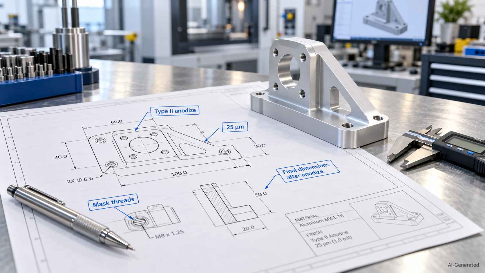
CNC drawing with anodizing thickness specifications
Specify the Anodizing Type and Thickness
For an anodized CNC part, the drawing should identify the applicable anodizing specification, coating type and class where required, color when relevant, and any specific coating thickness requirement. Do not rely on “Type II” or “Type III” alone when a particular coating thickness is critical to the part's function.
For close-tolerance parts, identify the final coated dimension and, where useful for manufacturing control, the corresponding pre-anodize machining dimension. Assembly-critical bores, threads, shafts, and mating faces should clearly state whether the dimensional limits apply after anodizing. If selected surfaces must remain uncoated, specify the masking or plugging requirement directly on the drawing.
Define Critical Dimensions After Anodizing
Dimensions that are critical at assembly or inspection should state whether their limits apply after anodizing. The drawing can also identify surfaces that demand masking and features that must be free of coating. This gives the machinist, anodizer, and inspector one finished requirement to follow. This is particularly important for threaded features and close-tolerance holes, where MIL-PRF-8625F provides specific guidance on dimensional effects.
Q: Does anodizing thickness vary across different areas of the same part?
Yes. Local coating thickness can differ from the average value. In small holes and tapped holes, MIL-PRF-8625F notes that coating thickness can vary from no film to a full normal coating. This is the reason why specifications may distinguish between average and local measurements.
Q: Can anodizing thickness be measured on a finished CNC part?
Yes. ASTM B244 provides a nondestructive eddy-current method for measuring anodic coatings on aluminum. It suits many finished CNC surfaces where the probe can take a reliable reading.
Q: Does anodizing make holes smaller?
Yes. When both walls of a bore are anodized, outward coating growth reduces the bore diameter. Using the 0.5× growth relationship from MIL-PRF-8625F as a planning estimate, a coating of thickness t reduces the bore diameter by approximately t across the two coated walls. Actual hole-size change can vary with the anodizing process, alloy, and hole geometry.
Q: Does aluminum alloy affect anodizing thickness or dimensional change?
Yes. Alloy chemistry changes how aluminum responds during anodizing. This can influence oxide development and resulting dimensional change. A Type II anodizing typical thickness target therefore needs to be considered alongside the selected alloy and process conditions.
Q: Does anodizing have a thickness tolerance?
It can. The permitted variation depends on the governing specification, drawing, or purchase requirement rather than one universal value for every anodized part. Under MIL-PRF-8625F, Type III coatings up to 0.002 in (50.8 µm) are generally subject to a ±20% thickness-variation limit unless otherwise specified. For coatings over 0.002 in, the specification gives a variation limit of ±0.0004 in (0.4 mil), unless otherwise specified. The applicable drawing or purchase requirement should control the final acceptance criteria.
Q: Should critical dimensions be specified before or after anodizing?
Assembly-critical dimensions are best defined as finished-part requirements after anodizing. Pre-anodize machining values are chosen to support those limits. This gives inspection a final dimensional target that is linked to the condition in which the component will be used.
Precision CNC Machining Service
Professional manufacturing, fast turnaround, and quality assurance.
Conclusion: Anodizing Thickness and Dimensional Control
Anodizing can affect the final dimensions of a CNC aluminum part, particularly when tight tolerances are involved. Defining the finished anodized requirement before machining helps account for dimensional changes during finishing and reduces the risk of rework. For parts with demanding dimensional requirements, JLCCNC can review the machining and anodizing requirements together before production. Upload your CAD file to get a fast quote starting from $1, with lead times as short as 3 days.
Popular Articles
• Surface Finish in Machining, Types, Charts & Testing
• Anodizing vs. Hard Anodizing: The Differences in Surface Treatment Techniques
• Anodized Aluminum Colors: Options, Limits, and Real-World Results
• Explanation of different material surface treatment technologies in CNC machining
• How to choose between Laser marking and UV printing?
Keep Learning
Surface Finish in Machining, Types, Charts & Testing
What is Surface Finish in Machining? At its core, surface finish in machining refers to the small-scale irregularities left on the surface of a part after machining. These irregularities are typically grouped into three categories: Roughness: The fine, closely spaced deviations caused by the cutting process itself. Roughness depends heavily on feed rate, tool sharpness, and cutting speed. Waviness: Larger, more widely spaced variations caused by machine tool vibration, deflection, or thermal distortio......
CNC Machining Surface Roughness: A Practical Guide
Why Surface Roughness Matters in CNC Machining When we talk about CNC machining, precision isn't just about hitting the right dimensions, it’s also about how the surface feels and performs. Surface roughness describes the fine irregularities left on a machined surface, and it directly impacts how a part behaves in the real world. So, what is surface roughness? In simple terms, it's the measure of tiny peaks and valleys created by the cutting process. While they might look smooth to the naked eye, thes......
Optimizing Manufacturing Efficiency: A Guide to Computerized Numerical Control (CNC) Machining Surface Finishes
CNC Surface Finishes: Types, Costs, and How to Choose Quick Answer: Choose an as-machined finish when cost and dimensional stability matter most. Use bead blasting or brushing for a uniform cosmetic appearance, anodizing for aluminum corrosion resistance, hard anodizing for wear, and laser marking or UV printing for identification. Confirm material, tolerance, color, masking, and end-use environment before quoting. A CNC-machined part comes off the machine functional but rarely finished — tool marks, ......
Anodizing vs. Hard Anodizing: The Differences in Surface Treatment Techniques
Quick Answer: Choose Type II anodizing when corrosion resistance, color, and cosmetic appearance are the main requirements. Choose Type III hard anodizing when the part needs greater wear resistance and the coating thickness can be accommodated in the fit and tolerance plan. Confirm alloy, coating thickness, color, sealing, and critical dimensions before release. An aluminum bracket for an outdoor enclosure and a hydraulic cylinder rod both might get anodized — but specifying the same process for both......
How to Remove Anodizing from Aluminum Parts
Key Takeaways Chemical stripping is commonly used when anodizing needs to be removed from most or all of an aluminum part, but the process can also attack the underlying aluminum if it is not controlled. Mechanical removal works well for accessible areas but can change the surface texture and remove more base metal than intended. CNC machining gives better control when a defined anodized area needs to be removed from a precision part. Laser-based removal can be useful for controlled localized treatmen......
Anodizing Thickness: How Much Does It Add?
Anodizing Thickness and Dimensional Change at a Glance Feature Approximate dimensional effect One coated external surface +0.5 × coating thickness Outside diameter across two coated surfaces +1 × coating thickness Bore diameter with two coated walls −1 × coating thickness 60° thread pitch diameter Changes by about 4 × surface-growth amount, or about 2 × coating thickness under the 0.5× growth assumption Dimensional estimates below use the 0.5 × coating-thickness surface-growth relationship given in MI......