Shoulder Milling in CNC Machining: Tools, Accuracy, and Cutting Strategy
19 min
- What Is Shoulder Milling (And What Defines a True Shoulder)
- How Shoulder Milling Forms Vertical Walls
- Square Shoulder Milling: How To Achieve True 90° Edges
- Shoulder Milling Cutters And Tooling Selection
- Force–Deflection–Surface Relationship in Shoulder Milling
- Deep Shoulder Milling: Challenges And Control Methods
- What Affects Shoulder Accuracy And Surface Quality
- Shoulder Milling Vs End Milling Vs Face Milling
- When To Use Shoulder Milling (And When Not To)
- Limitations And Trade-Offs of Shoulder Milling
- Design Guidelines For Shoulder Milling (DFM)
- Typical Applications Of Shoulder Milling
- Precision CNC Milling Services at JLCCNC
- FAQ’s About Shoulder Milling
Key Takeaways About Shoulder Milling
- Shoulder milling is used to create stepped faces where a vertical wall meets a flat surface in prismatic parts such as pockets, seats, and structural transitions.
- The cutter side forms the wall while the bottom edge forms the floor, so any change in cutting load directly affects wall position and surface condition.
- Deeper cuts increase tool bending, which can shift the wall in steel and other hard materials, so depth must be controlled in stages.
- Cutter choice affects results: short, solid tools give better wall control, while long reach and indexable tools need lighter engagement to stay stable.
- Heavy side cutting increases heat and vibration, and enclosed pockets need careful chip removal to avoid re-cutting and wall damage.
A shoulder mill is typically used in CNC machining when vertical wall control and defined step geometry are required, particularly in parts where a flat surface meets a near-perpendicular wall. The process depends heavily on how the cutter engages the material, since the tool edge defines both the vertical wall and the floor of the step in a single pass. In practice, wall condition is not only a function of tool shape, but also of tool deflection, engagement width, and how cutting load is distributed during the cut.
In production conditions, shoulder milling is often applied in parts that require controlled step features such as pockets, fixture bases, and structural housings. The challenge increases when depth grows, since tool reach introduces bending stress and vibration at the cutting zone.
Under these conditions, maintaining stable wall geometry depends more on cutting strategy and tool selection than machine capability alone. Cutter diameter, stick-out length, and feed direction all influence how the final shoulder face behaves after machining.
Keep on reading to explore all about the shoulder milling process, tools, geometries, challenges, controls, and typical applications.
What Is Shoulder Milling (And What Defines a True Shoulder)
Shoulder milling is a CNC machining process used to form a stepped geometry where a vertical wall meets a flat surface at a controlled angle, usually close to 90 degrees.
The feature is defined by part geometry, not by the tool itself, because the cutter defines both the wall and the floor in one engagement.
A true shoulder is a functional step in a component where both faces carry design intent. The vertical wall must stay aligned within defined limits, while the horizontal surface must remain flat to support assembly, fit, or load transfer.
This separates shoulder milling from general side milling, where only wall removal is targeted without strict control of the bottom face.
In actual machining, shoulder formation depends on how the cutter interacts with the material along both radial and axial directions. The side of the tool forms the vertical face, while the tool bottom defines the step surface.
Any change in cutting load or tool deflection can shift the wall position or affect the floor condition, especially in deeper cuts or harder materials.
How Shoulder Milling Forms Vertical Walls
Shoulder milling creates vertical walls through side engagement of the cutter along the workpiece edge. The wall is generated by controlled contact between the tool flank and the material. The final wall condition depends on how cutting forces behave during this engagement.
Peripheral Cutting Engagement And Material Removal
- The cutter remains in continuous side contact along the wall height during machining, shaping the vertical profile in a single pass.
- Chip removal follows the cutter path along the wall, which directly influences surface condition and cutting load distribution.
- Engagement length changes the amount of material removed per pass, which affects how the wall develops across depth.
Force Direction Relative To Wall Geometry
- Radial force typically dominates in shoulder milling compared to axial load.
- Cutting force acts sideways against the wall, which guides how the tool reacts during material removal.
- The vertical force component helps maintain depth control, while the sideways force influences wall position.
- Combined force direction defines how cleanly the cutter follows the programmed wall path.
Why Vertical Wall Formation Is Sensitive To Radial Load
- Higher radial load pushes the cutter away from the intended wall line, shifting the final geometry.
- Uneven load during entry and exit creates small variations along the wall height.
- Longer tool reach increases sensitivity to radial force, which affects wall consistency in deeper cuts.
Square Shoulder Milling: How To Achieve True 90° Edges
Square shoulder milling cutter with design illustration showing cutting edges. (Source: sandvik.coromant.com)
A nominal 90° shoulder geometry is difficult to achieve in CNC milling because the cutter shape inherently influences the corner zone. The tool defines both the wall and floor transition, so the resulting edge is governed by insert geometry, corner radius, and tool exit conditions. In practice, a functional square shoulder with a tool radius constraint is produced rather than a perfectly sharp 90° intersection.
Insert Geometry Limits And Corner Radius Reality
- Cutting inserts carry a corner radius that prevents a sharp internal corner at the intersection of the wall and the floor.
- A smaller radius gives a closer shoulder angle, but it increases edge stress on the tool during cutting.
- The actual corner shape is formed by the tool tip geometry, not by the programmed tool path.
Finishing Strategies For Correcting Wall Angle Deviation
- Light finishing passes help reduce the visible mismatch between the wall and floor after roughing cuts
- Lower feed during finishing improves control over wall alignment across the full depth
- Re-cut passes along the same wall path help remove minor angle drift from earlier cuts
Edge Condition Control (Sharp Vs Controlled Radius)
- A fully sharp edge is limited by tool geometry, so it is rarely achieved in direct milling
- Controlled radius edges are used when parts need better contact behavior in assembly and load zones.
- The final edge condition depends on whether the design prioritizes fit accuracy or edge strength in service conditions.
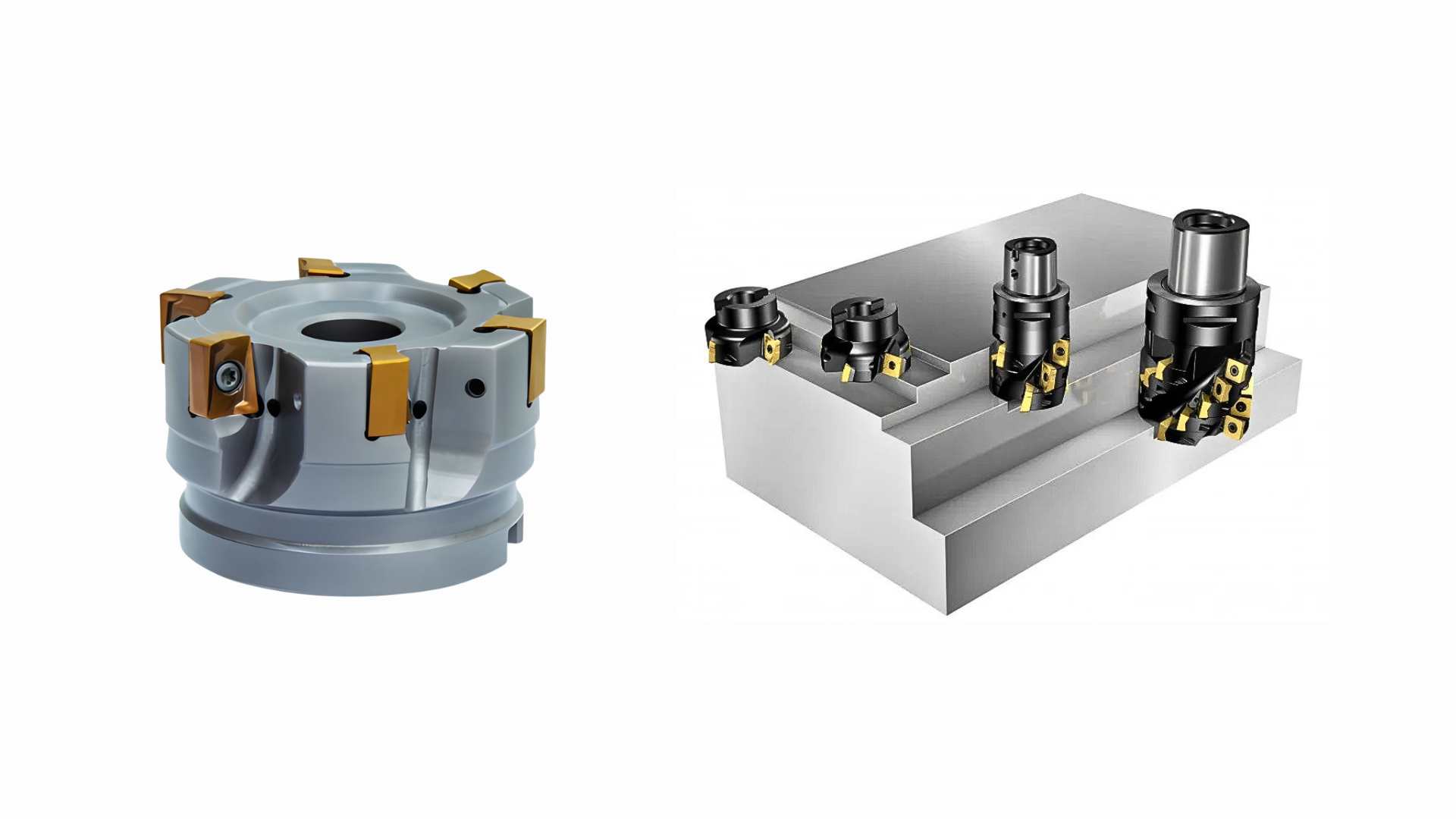
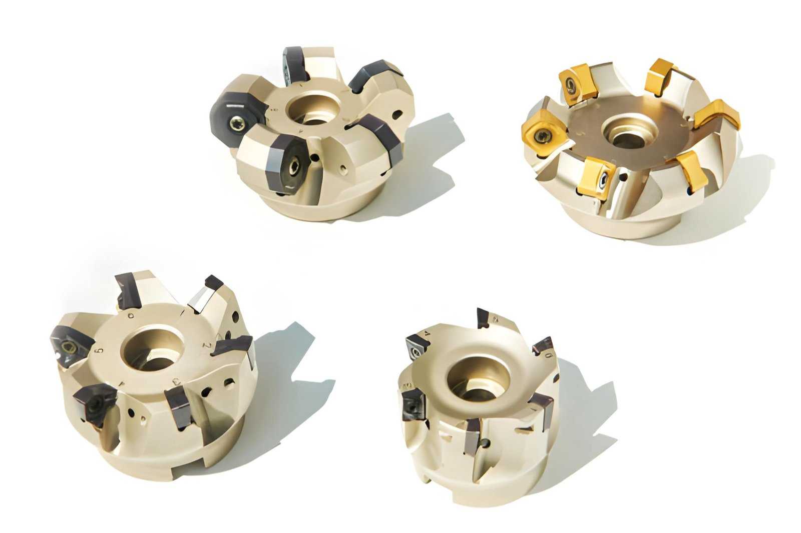
Shoulder Milling Cutters And Tooling Selection
The image shows shoulder milling cutters used in CNC machining for creating flat surfaces and square shoulders on metal parts. (Source: iStock)
Tooling selection in shoulder milling affects wall position and surface condition. Cutter type, diameter, overhang, and holder setup decide how the tool behaves during cutting. Most wall issues come from setup choices rather than machine limits.
Indexable Vs Solid End Mills For Shoulder Features
Solid carbide end mills are used for smaller shoulder features where wall control matters. Common sizes include 6 mm to 20 mm in steel and stainless steel work. Therefore, they are preferred in lighter cuts and tighter geometry.
Indexable shoulder mills such as Sandvik Coromant CoroMill 390 or Kennametal Mill 1-12 are used for larger parts. These tools start around 25 mm in diameter and handle heavier stock removal.
Whereas solid tools focus on precision, indexable systems focus on material removal. Insert condition and seating also influence the wall finish.
Tool Diameter, Overhang, And Rigidity Relationship
A larger tool diameter gives better control over wall position during cutting. Smaller tools react more to cutting load, especially in deeper pockets. Thus, diameter selection directly affects shoulder quality.
Overhang also plays a key role. Longer reach increases bending during cutting. Therefore, keeping tool length short helps maintain wall position in steel and alloy parts. Also, shorter tools respond better under load changes.
Toolholder Runout And Its Effect On Wall Accuracy
Runout changes how cutting edges share load during machining. As a result, the wall position can shift slightly during shoulder milling.
Hydraulic and shrink-fit holders keep better alignment than standard collet systems. Whereas collet holders are flexible, precision holders reduce imbalance during cutting. Even a small runout (e.g., above 0.01 mm) can become visible on long shoulder walls in steel components.
Cutting strategy in shoulder milling sets how the cutter enters material, how much side contact it carries, and how the wall is formed across depth. Each setting directly changes wall position, surface marks, and tool load behavior during cutting.
Radial Engagement Vs Wall Accuracy Trade-Off
- Around 30% to 50% radial engagement is commonly used in conventional shoulder milling of steel, although optimal values depend on tool type and cutting strategy.
- Above 60% engagement increases side pressure, which can push the wall off line in deeper cuts.
Stepdown Planning For Controlled Load
- Roughing stepdown often falls in the 2 mm to 4 mm range for medium-sized tools in steel, but it should be adjusted based on tool diameter, rigidity, and material condition.
- Finishing stepdown is kept around 0.5 mm to 1 mm to clean the wall without shifting position.
Feed Consistency And Chip Formation Stability
- Feed range of 0.05 to 0.15 mm/tooth keeps chip size uniform on shoulder passes in the steel.
- Feed dropping below the stable range leads to rubbing on the wall instead of clean cutting.
- Feed spikes above the range increase tool pressure marks along the vertical surface.
Force–Deflection–Surface Relationship in Shoulder Milling
Shoulder milling behavior can be interpreted through a simple force–deflection–surface relationship rather than isolated cutting parameters.
Radial cutting force acts perpendicular to the wall and directly influences lateral tool deflection. As radial load increases, the cutter tends to bend away from the programmed path, which appears as a wall shift or taper, especially in deeper cuts.
Axial force contributes mainly to depth stability. While it affects tool load along the spindle direction, it has less direct influence on wall position compared to radial components.
Tool overhang introduces a bending moment at the cutter tip. Once the overhang exceeds a stable range (often around 3× tool diameter), even moderate radial loads can produce measurable deflection along the wall height.
Surface condition reflects the dynamic response of the system. Vibration, intermittent cutting load, or uneven engagement leaves a visible signature on the wall, often observed as waviness, chatter marks, or inconsistent texture.
In practice, wall accuracy, straightness, and surface finish are not controlled independently. They emerge from the combined effect of force direction, tool stiffness, and cutting stability during the operation.
Deep Shoulder Milling: Challenges And Control Methods
Deep shoulder milling increases cutting length along the wall, which changes tool behavior under load. This is where engineering review becomes essential in production CNC machining services.
As depth increases, tool reach becomes longer, and wall control becomes harder to maintain in one pass. Most control comes from breaking the cut into planned stages.
Tool Deflection Under Long Overhang Conditions
- Overhang above 3× tool diameter increases bending at the cutting edge, especially in steel shoulder cuts.
- Deflection shows up as a wall shift near deeper sections, even when the top section looks correct.
- Shorter tool reach reduces bending and helps keep the wall line closer to the programmed path.
Wall Taper And Straightness Deviation In Deep Cuts
- Wall taper increases when the cutting force weakens along depth due to tool reach and chip load variation.
- Deviation is more visible in tall shoulders, with a depth range of 15 mm to 30 mm in steel parts, depending on tool diameter and setup rigidity.
- The entry zone and bottom zone often show a slight mismatch when single-pass cutting is used.
Multi-Pass And Staged Machining Strategies
- Roughing pass removes bulk material in 2 mm to 5 mm step-downs before finishing the wall cut.
- Semi-finishing pass reduces remaining stock to around 0.2 mm to 0.5 mm before the final wall pass.
- Final pass uses low radial engagement to correct the wall line without reloading the full cutting force on the tool.
What Affects Shoulder Accuracy And Surface Quality
Shoulder accuracy depends on tool support, cutting load, and how the cutter behaves during side contact with the material. The vertical wall reflects any change in setup, feed, or engagement condition. Surface condition follows the same pattern and shows directly on the shoulder face.
Tool Deflection And Dimensional Deviation
- Long tool reach creates bending under the side cutting load, which shifts the wall position away from the programmed line.
- Steel and stainless steel increase cutting resistance, which makes the wall shift more visible in deeper cuts.
- Larger diameter cutters keep the wall line more stable compared to small diameter tools under similar depth.
Chatter And Vibration On Vertical Walls
- Uneven cutting contact produces vibration marks that appear as waviness on the shoulder surface.
- Long overhang setups increase vibration because the tool loses stiffness during cutting.
- Reducing tool reach and keeping engagement light helps keep the wall surface cleaner.
Burr Formation And Edge Integrity
- Burr forms when material stretches instead of separating cleanly at the tool exit point.
- Stainless steel and tough alloys show stronger burr formation along shoulder edges.
- Light finishing passes and controlled exit reduce edge damage and improve corner condition.
Shoulder Milling Vs End Milling Vs Face Milling
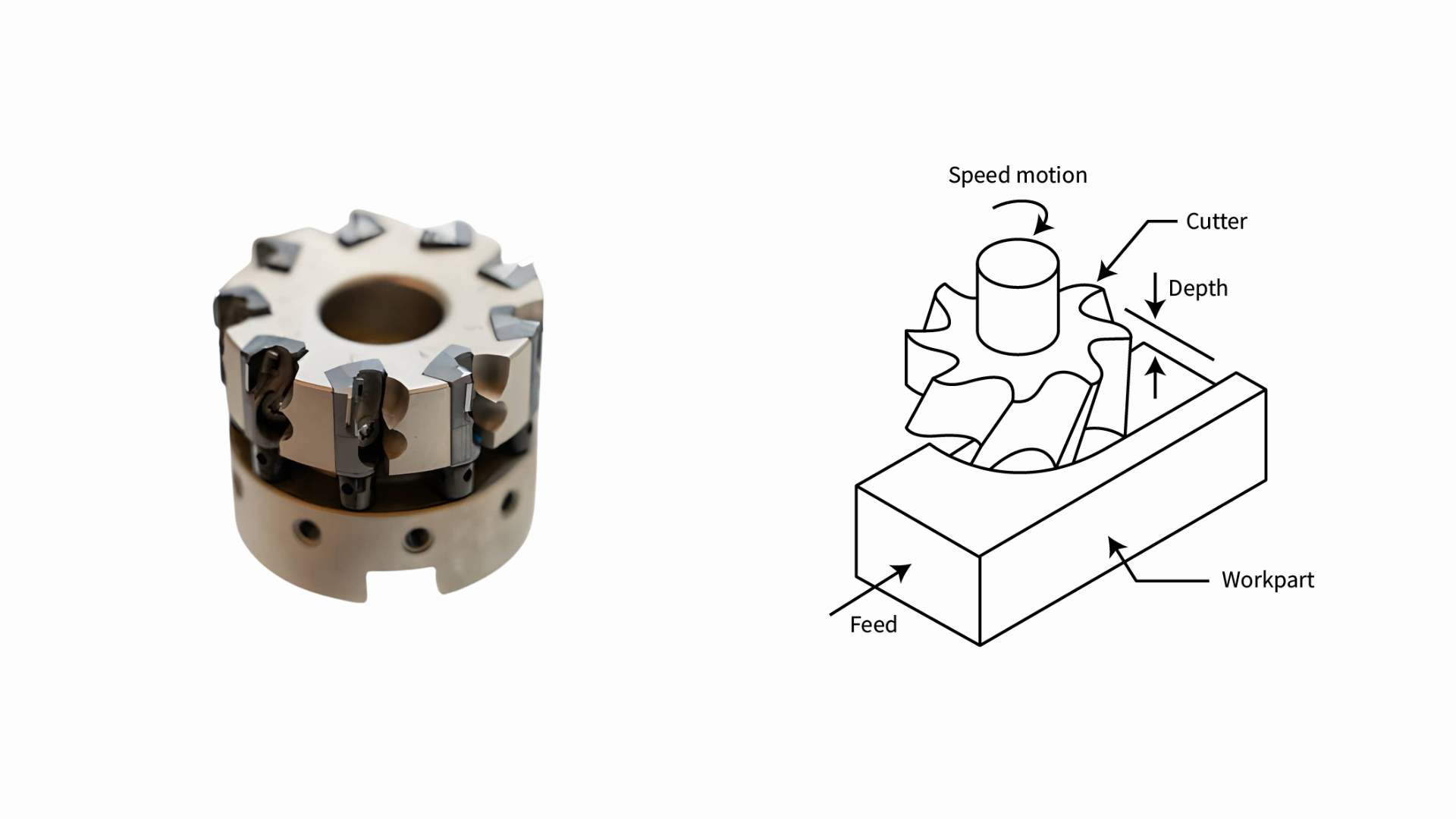
The image depicts a face milling cutter with carbide inserts and a labeled illustration. (Source: spee3d.com)
These three operations are often used on the same part, but each one works under a different cutting condition. The main difference comes from how the cutter engages the material and what surface it is meant to generate. Selection depends on wall requirements, flatness needs, and cutting direction.
The differences become clearer when compared side by side:
| Parameter | Shoulder Milling | End Milling | Face Milling |
|---|---|---|---|
| Cutting engagement | Side + bottom | Side + bottom (variable path) | Top surface contact |
| Force direction | Mainly lateral | Mixed direction | Vertical downward |
| Geometry use | Vertical walls and steps | Pockets and profiles | Flat surfaces |
| Wall control | High | Medium | Not applicable |
| Flatness control | Medium | Medium | High |
| Material removal rate | Medium | Medium | High |
| Best use case | Shoulder features | Complex shapes | Surface finishing of flats |
Differences In Engagement And Force Direction
Shoulder milling uses side engagement to form a vertical wall and bottom face in one cut. The force acts mainly sideways, which directly influences the wall position during cutting.
End milling also uses side and bottom cutting, but it is applied for general pocketing and contour work rather than controlled shoulder formation. Force direction changes frequently as the tool moves along curves and pockets.
Face milling works mainly on top surfaces. The cutter engages the material across its face, and the force stays mostly vertical, which supports flat surface generation rather than wall control.
Geometry Suitability For Each Method
Shoulder milling is suitable for steps, ledges, and vertical walls where a clear edge between two planes is required. It is commonly used in fixture bases and structural housings.
End milling is used for pockets, slots, and general 3D shapes where geometry changes across the tool path. It handles mixed surfaces but does not define precise shoulder edges.
Face milling is used for large flat surfaces like plate tops, machine bases, and mounting faces. It is not used for vertical wall formation.
Accuracy And Efficiency Trade-Offs
Shoulder milling provides better control over wall position but needs controlled engagement and tool setup. It is less efficient for bulk removal compared to face milling.
End milling offers flexibility in complex shapes, but wall accuracy depends on tool path and deflection control. Face milling removes material faster on flat surfaces, but it cannot control vertical geometry.
When To Use Shoulder Milling (And When Not To)
Shoulder milling is selected when a part needs a defined step between a vertical wall and a flat surface. It is most effective when geometry requires a clear edge and controlled wall position. It becomes less suitable when surface finish or deep stability becomes the main challenge.
When Square Edges Define Assembly Fit
- Used in fixture bases where parts must locate against a flat surface and a vertical stop face.
- Applied in housings and brackets where mating components depend on a clear shoulder contact.
When Vertical Wall Accuracy Is Critical
- Selected for pockets and steps where wall position controls part alignment during assembly.
- Used when the tolerances on the wall location are tighter than the pocket milling capability.
When Alternative Methods Are More Stable
- Face milling is preferred when only a flat surface condition is required without vertical wall control.
- Profile or contour milling is used when geometry changes continuously, and shoulder formation is not needed.
Limitations And Trade-Offs of Shoulder Milling
Shoulder milling performs well for defined steps and vertical walls, but it has limits in load handling and depth conditions.
As tool reach and engagement increase, control over the wall and surface condition becomes harder. The process also becomes less efficient when the material removal volume is high.
Deflection Risk In Long Tools or Thin Walls
- Long tool reach bends under the side cutting load, which shifts the wall position in deeper cuts.
- Thin-wall sections flex during machining, which affects final wall alignment and surface condition.
Efficiency Limits In Heavy Material Removal
- Shoulder milling removes material in controlled passes, which increases cycle time in bulk stock conditions
- High engagement is needed for fast removal, which increases the tool load and reduces wall control quality.
Constraints In Deep or Restricted Features
- Deep pockets limit chip evacuation, which affects the cutting condition along the full wall height.
- Restricted access reduces tool movement, which forces lighter cuts and multiple passes for completion.
Design Guidelines For Shoulder Milling (DFM)
Shoulder milling performs best when the part is designed to support smooth tool entry and controlled side cutting.
Geometry choices made at the design stage directly affect wall quality and machining time. Simple adjustments in wall proportions, allowance, and access space help reduce cutting load and improve machining flow.
Wall Height-To-Thickness Ratio Considerations
Wall height and thickness should stay balanced to avoid movement during cutting. In steel and stainless parts, a wall height within 4 to 6 times its thickness works better for controlled machining.
When the wall becomes too tall and thin, it starts reacting to cutting pressure, which affects wall position and increases correction work during finishing.
Finishing Allowance Planning
A small finishing allowance helps control final wall condition without stressing the tool during rough cuts. Leaving around 0.2 mm to 0.5 mm stock on the shoulder walls allows the final pass to clean the surface and correct small deviations.
If no allowance is left, the cutter has to remove full material in one pass, which can affect wall consistency.
Geometry Optimization To Reduce Cutting Load
Shoulder areas should allow enough space for smooth tool entry and exit. Tight internal corners that match the tool radius increase cutting resistance and make engagement less smooth.
Pocket width is better kept slightly larger than tool diameter, around 1.2×, so the cutter can move without restriction and maintain better wall formation during cutting.
Typical Applications Of Shoulder Milling
Shoulder milling is used when a part needs a defined step between a vertical wall and a flat surface. The feature supports positioning, support, and assembly functions. It is selected based on geometric needs rather than the type of industry.
Structural Step Features And Load-Bearing Parts
Shoulder milling is used in parts where a step surface carries load, and the vertical wall works as a stop or alignment face. These features are common in base structures and support frames. The accuracy of the step affects how well the part sits and transfers load during operation.
Precision Housings And Mounting Interfaces
This process is used in housings where internal steps guide part positioning during assembly. It is also used in mounting interfaces where components must sit in a fixed location. The shoulder helps control alignment between mating parts and keeps the assembly position consistent.
Components Requiring Controlled Edge Geometry
Shoulder milling is used in parts where the edge between two surfaces affects fit or contact. The vertical wall and flat surface must meet in a controlled manner to support sealing, location, and repeated assembly contact. This makes the edge function more important than appearance alone.
Precision CNC Milling Services at JLCCNC
At JLCCNC, we provide CNC milling services for parts that require controlled steps, vertical walls, and flat-to-wall geometry in steel, stainless steel, aluminum, and tool materials. Our engineering team checks each drawing to confirm tool access, wall depth, and cutting strategy before machining starts.
We handle both prototype and production runs where shoulder features must maintain consistent wall position and flatness across batches. This includes structural parts, fixture bases, and precision housings where step geometry is critical for assembly and alignment.
Our support includes:
- Free DFM review before machining starts to check wall depth, tool access, and step geometry
- Engineering support for cutter selection, stepdown planning, and cutting strategy for stable wall formation
- Shoulder milling for steel, stainless steel, aluminum, and tool steel components with controlled wall accuracy
Upload your CAD file to JLCCNC to get an instant quote starting from $1. Parts with controlled shoulder geometry can be scheduled with lead times as short as 3 days, depending on complexity and material.

Precision CNC Machining Service
Professional manufacturing, fast turnaround, and quality assurance.
FAQ’s About Shoulder Milling
Q: What Is Shoulder Milling Used For?
Shoulder milling is used to create a step between a flat surface and a vertical wall. It is used when both faces must be controlled for fit or positioning. This is common in parts that need clear locating edges.
Q: What Is A Shoulder Milling Cutter?
A shoulder milling cutter is a tool that cuts both the wall and the flat surface in one pass. It can be a solid end mill or an insert-type cutter. The tool shape helps form the step feature directly.
Q: How To Achieve A True Square Shoulder?
A true, sharp 90-degree corner is not fully possible because cutters have a small radius. A close square edge is achieved using the right cutter and a light finishing pass. Design must also allow for the tool radius at the corner.
Q: What Causes Wall Taper In Shoulder Milling?
Wall taper happens when the tool bends during deeper cutting. It is more common with long tools and hard materials like steel. Higher cutting depth also increases this effect.
Q: When Is Deep Shoulder Milling Difficult?
Deep shoulder milling becomes difficult when the tool is long and the cutting depth is high. The tool can bend and affect the wall position. Narrow spaces also make chip removal harder during cutting.
Popular Articles
• Cutting with Precision: A Comprehensive Guide to CNC Water Jet Technology
• CNC Coolant Explained: Types, Maintenance & Safety
• Rake Angle in Machining: Machinists’ Guide to Perfect Cuts
• What Steps Are Taken To Minimize Waste In CNC Machining Processes?
• How EDM Wire Cutting Works: Complete Guide to Precision CNC Wire Cutting
Keep Learning
Chatter in Machining: Causes, Effects, and How to Reduce It
CNC milling operation producing visible chatter marks on an aluminum workpiece Quick Chatter Diagnosis Checklist Symptom Most Likely Cause First Action High-pitched squeal Regenerative chatter Change spindle speed ±15% Chatter only in deep pockets Excessive tool overhang Shorten tool Chatter on thin walls Low workpiece rigidity Improve fixturing Chatter after tool replacement Runout / holder issue Check tool holder Chatter only during finishing DOC too small / rubbing Increase feed or adjust speed It ......
What Is Tool Offset in CNC? Types, Setup & Best Practices
CNC tool offset setup with measurement overlay Key Takeaways CNC offsets connect programmed intent with actual cutter position. Length data guides Z-axis depth control. Radius data protects part size during contour milling. Geometry values define the cutter's measured baseline. Wear values support fine correction during production. Verified data lowers scrap risk before full machining. Good offset habits protect tools, fixtures, and parts. In the context of CNC machining , tool offset is the quiet set......
Trochoidal Milling: Complete Guide to High-Efficiency CNC Machining
Key Takeaways Trochoidal milling combines circular cutter motion with continuous forward feed. The cutter normally engages 5 to 20% of its diameter instead of making a full-width cut. A smaller engagement angle limits force changes during slotting and pocket roughing. Low radial engagement often allows greater axial depths of cut than conventional slot milling. CAM software calculates the circular path automatically from the selected machining parameters. This strategy is widely applied to titanium, s......
What Is Die Casting? Process, Materials, and Applications
Key Takeaways Die casting is a metal casting process that forces molten metal into a reusable steel mold under high pressure, producing parts with tight tolerances and good surface finish at high volume. Aluminum die casting is the most common form by far, thanks to its combination of light weight, decent strength, and good corrosion resistance. The die casting process runs through mold preparation, injection, cooling, and ejection in a cycle that can repeat every few seconds to minutes depending on p......
First Angle vs Third Angle: Understanding Orthographic Projection Methods
Key Takeaways Orthographic projection is the system that lets a 3D part be represented through multiple 2D views, front, top, side, and so on. First angle projection and third angle projection are the two standard methods for arranging those views, and they place views in opposite positions relative to the object. First angle projection is the ISO standard used across most of Europe, India, China, Russia, and many other countries following ISO standards Third angle projection is the standard in the Un......
Micro EDM Machining: Capabilities, Materials, and Applications for Precision Components
Key Takeaways About Micro EDM Machining Only electrically conductive materials can be machined. Hole diameters can reach below 50 μm on specialized equipment. The process produces almost no mechanical cutting force, making it suitable for thin or delicate features. Surface integrity still requires attention because recast layers and heat-affected zones may remain after machining. Micro EDM is often combined with CNC machining, with milling producing the main geometry before EDM finishes critical micro......