Contour Milling: Toolpaths, Surface Machining, and CNC Programming Considerations
12 min
- What Is Contour Milling?
- Contour Milling Workflow in CNC Programming
- Types of Contour Milling Operations
- CNC Toolpaths Used in Contour Milling
- Tool Selection for Contour Milling
- Contour Milling CNC Programming Considerations
- Cutting Parameters in Contour Milling
- Surface Finish and Accuracy in Contour Milling
- Common Challenges in Contour Milling
- Materials Commonly Machined With Contour Milling
- Applications of Contour Milling
- Contour Milling vs Other Milling Operations
- Best Practices for Contour Milling
- Conclusion About Contour Milling
- FAQ About Contour Milling
Key Takeaways and Introduction About Contour Milling
- CNC machines can contour outer edges, inner limits, curved faces, and intricate shapes.
- The result relies on cutter shape, motion strategy, operating values, and program checks.
- Accurate dimensions call for engagement, spacing, movement, and setup.
- Methods can handle planar, freeform, and deep features, as well as multi-axis work.
- Material behavior, tool reach, vibration, deflection, and cycle duration affect consistency.
- Uses include molds, aerospace parts, medical components, and industrial equipment.
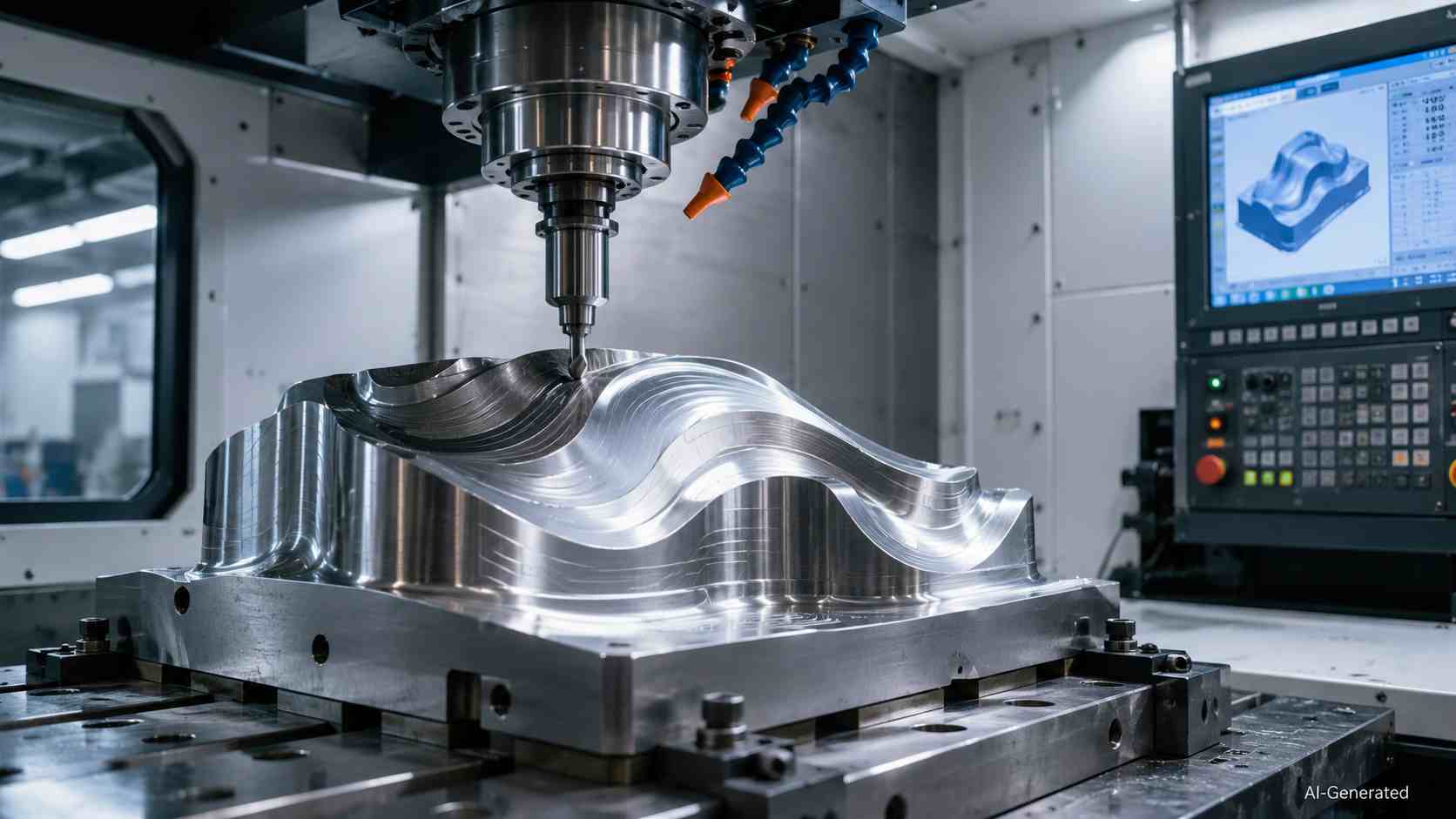
CNC machine contour milling a curved metal workpiece
Modern components may gain performance from their shape rather than size alone. Contour milling brings such designs into CNC production through coordinated cutting motion.
What Is Contour Milling?
Contour milling is a CNC milling operation in which the cutter follows a defined contour, boundary, or programmed path to generate part geometry. Depending on the machining strategy, the contour may be a two-dimensional profile, a stepped three-dimensional feature, or a freeform surface generated through successive tool movements.
In many CAM systems, contour milling is most commonly associated with profile machining along part boundaries. However, the same principle of controlled tool movement is also applied to more complex surface-contouring operations used in molds, aerospace components, and other freeform geometries.
How Contour Milling Works
Contour milling depends on coordinated axis movement as the CNC controller reads line, arc, spline, or other interpolated toolpath commands. It guides the cutter through changes in direction and elevation.
Contour Milling Workflow in CNC Programming
CAD model preparation:
The model is reviewed for complete geometry and a workable machining setup.
Toolpath generation:
CAM software creates cutter motion from the chosen operation and tool.
Simulation:
Virtual playback reveals collisions, excess travel, and uncut material before production.
Post-processing (G-code):
A machine-specific post processor translates CAM data into G-code.
Machining verification:
Final inspection checks the produced component against its design requirements.
Types of Contour Milling Operations
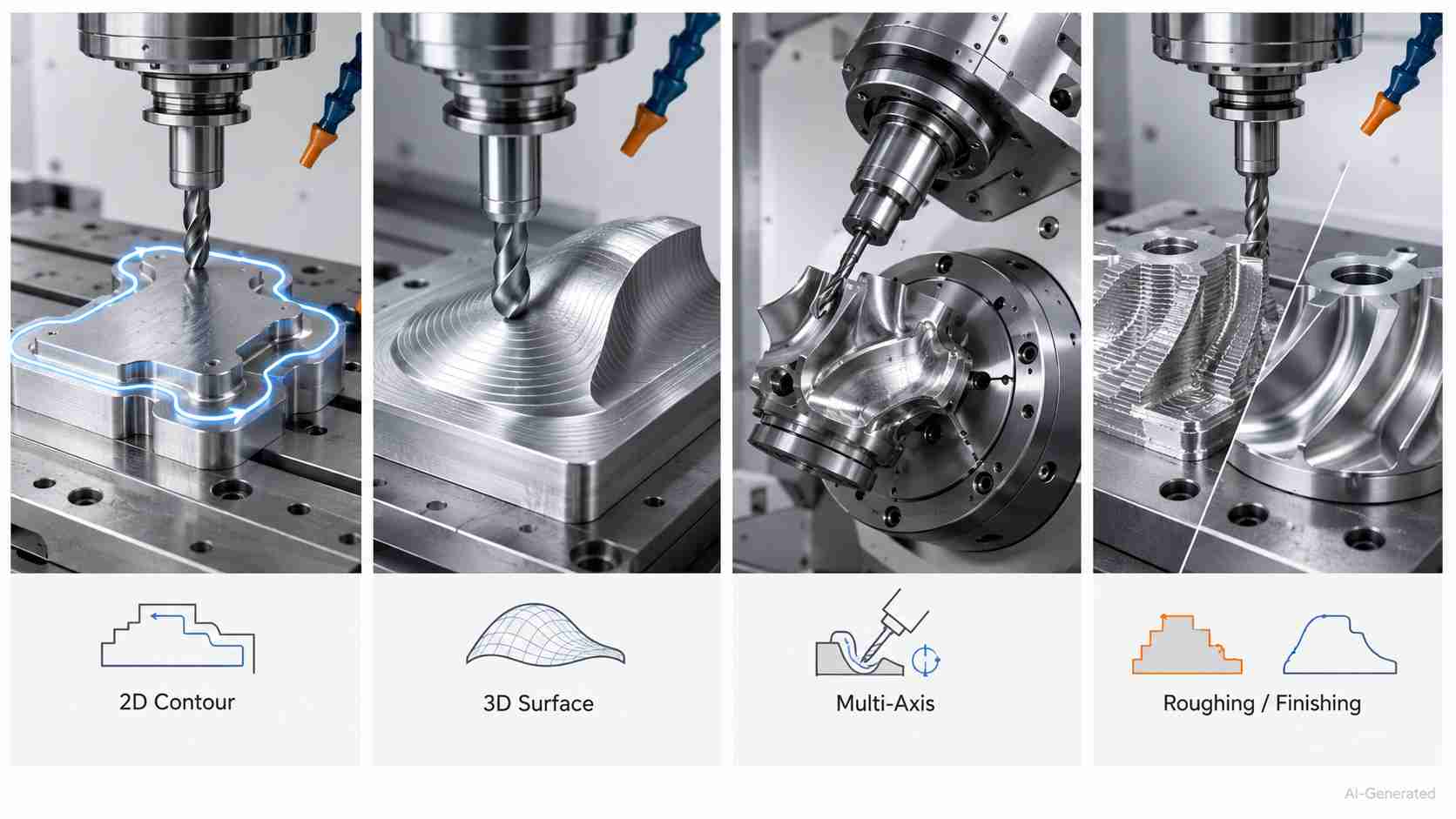
Types of contour milling operations in CNC machining
2D Contour Milling
2D contour milling follows programmed boundaries at fixed Z levels. It is commonly used to machine external profiles, internal walls, and other features that maintain a constant depth. This process results in the creation of vertical walls and plain outlines.
3D Surface Contouring
3D surface contouring uses successive tool passes across freeform geometry, allowing the cutter to follow changing elevations and curvature.
Multi-Axis Contour Milling
Whenever access is more difficult, the orientation of the cutter is adjusted by synchronised rotational movement to accommodate undercuts, wrapped features, and recessed areas.
CNC Toolpaths Used in Contour Milling
Parallel Toolpaths
Parallel toolpaths sweep across shallow surfaces in a single direction. Tighter spacing reduces scallop height and produces a finer surface finish.
Z-Level Toolpaths
In the next step, Z-level paths trace horizontal bands along steep walls. This helps to maintain contact more consistently while minimizing needless travel cuts.
Spiral and Morph Toolpaths
When applied to rounded or bounded locations, spiral and morph patterns maintain continuous motion, reduce retractions, and spread cutter marks more evenly.
Adaptive Toolpaths
Last but not least, an adaptive contour milling operation regulates engagement through flowing arcs. It eases corner loads as well as supports efficient material removal.
Tool Selection for Contour Milling
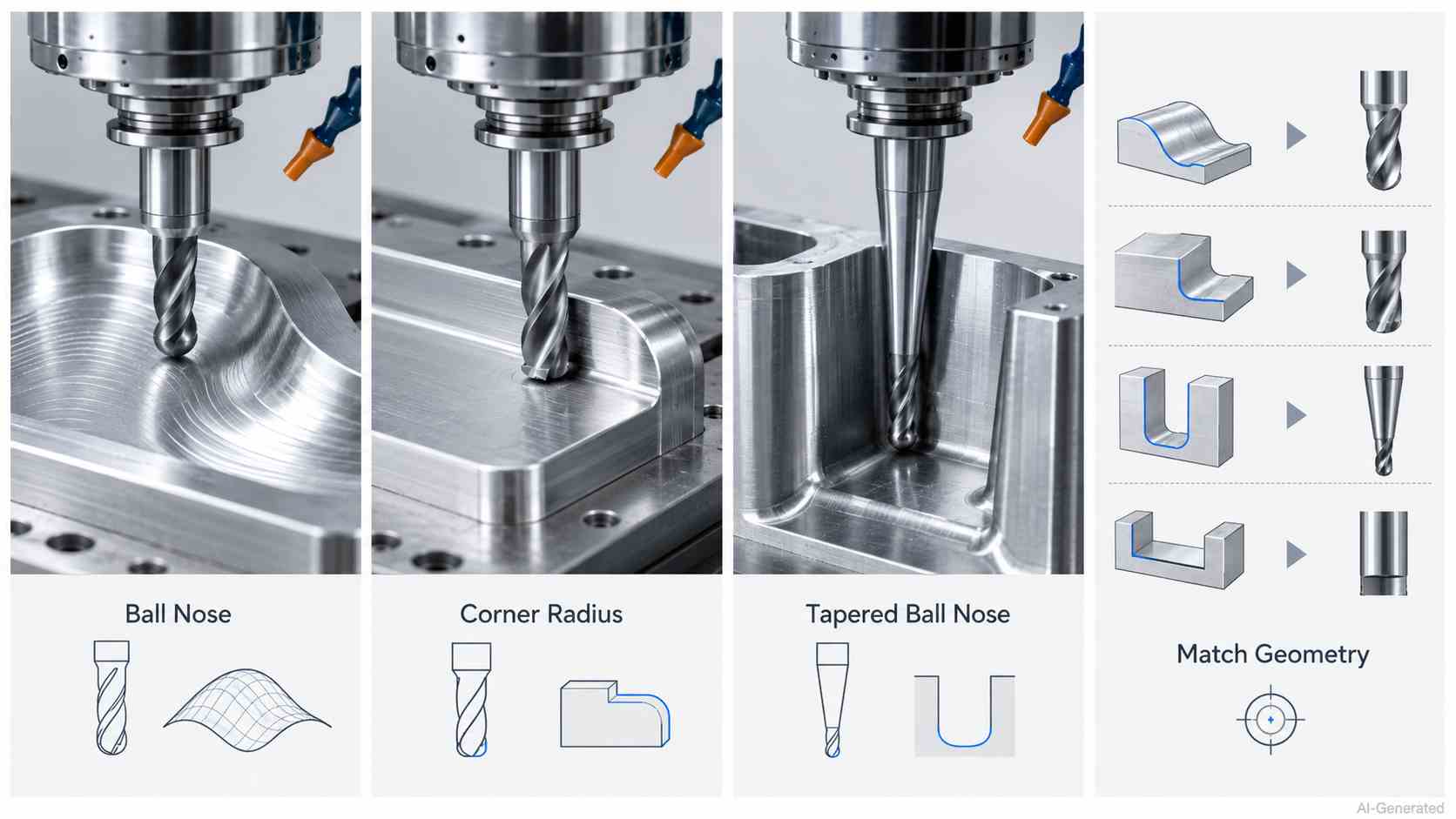
Contour milling cutters matched to surface geometry
Ball Nose End Mills
Ball nose end mills generate smooth transitions on sculpted surfaces. Note that such types of mills follow flowing curves and have a rounded cutting profile.
Corner Radius End Mills
When working with filleted edges and flatter regions, corner-radius end mills help support the cutting edge while simultaneously removing material effectively.
Tapered Ball Nose Cutters
Since the conical body of tapered ball nose cutters reduces bending when the rounded end approaches tiny details, these cutters are often used in deep cavities.
Matching Tool Geometry to Surface Features
A contour milling CNC program performs optimally when cutter diameter, tip form, and taper reflect each feature's curvature, access, as well as desired texture.
Matching tool geometry to surface features becomes more challenging as cavity depth increases and surface curvature changes across the part. In many cases, cutter diameter, tool reach, holder clearance, and machining strategy must be evaluated together rather than independently.
For parts with complex contours or difficult-to-access features, JLCCNC engineers typically review tooling feasibility during process planning to identify potential reach, deflection, or collision issues before production starts.

Precision CNC Machining Service
Professional manufacturing, fast turnaround, and quality assurance.
Contour Milling CNC Programming Considerations
CAD Model Preparation
The designer repairs any gaps, defines the stock, and establishes datums that will serve as anchors for each contour milling coordinate later on.
Toolpath Verification
The programmer then examines the sequence to ensure that it has lead-ins, exits, connecting segments, and boundary limitations before accepting it.
Tool Reach and Collision Analysis
During surface contour milling, flute length, neck spacing, holder placement, fixture closeness, and axis travel are the factors that are evaluated.
Machining Simulation Before Production
Machine-level simulation evaluates posted code with the selected kinematics. It confirms rotary behavior and controller interpretation before release.
Cutting Parameters in Contour Milling
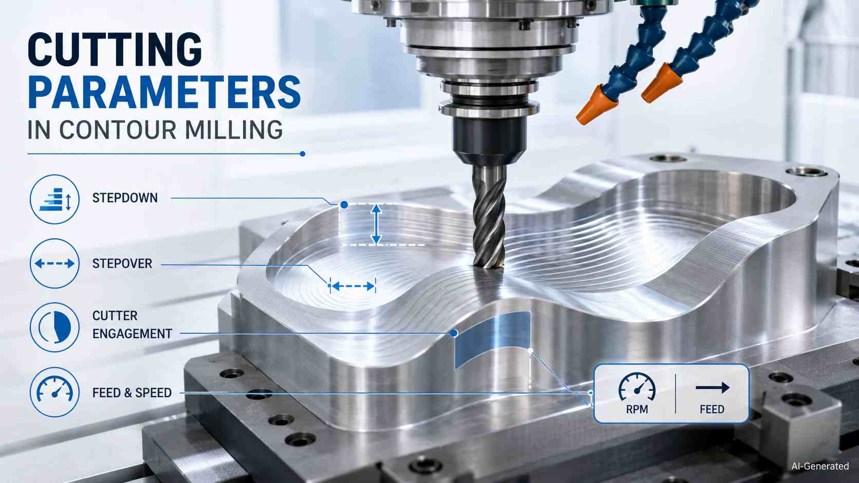
Contour milling cutting parameters and tool engagement
Stepdown Selection
At the outset, stepdown is used to determine the axial cut depth. This helps balance material removal against tool load and machine stability during contour milling.
Stepover Selection
Across each pass, stepover controls lateral spacing. Reducing stepover generally improves surface finish but increases machining time.
Cutter Engagement and Cutting Forces
The chip and cutting force also change when the radial contact shifts, which in turn affects vibration, edge stress, and the amount of power that is required.
Feed Rate and Cutting Speed Considerations
To finish the setup, every contour milling operation demands feed and speed values that are in accordance with tool diameter, workpiece material, and heat control.
Surface Finish and Accuracy in Contour Milling
Surface Scallops and Tool Marks
The process of contour milling results in the formation of residual cusps between adjacent cutter sweeps. Meanwhile, runout or edge wear may result in the appearance of visible streaks.
Accuracy on Curved Surfaces
Changing curvature, which extends beyond those traces, causes a change in the effective contact point. Deviations in interpolation may cause the desired form to be distorted.
Tolerance Considerations
From there, a contour milling CNC program has to take into consideration chordal variation, positioning capability, thermal drift, and cumulative setup error.
Secondary Finishing Requirements
When the outcome remains outside specification, the dimensions and appearance may be refined by the use of polishing, grinding, lapping, or a corrective pass.
Common Challenges in Contour Milling
Chatter and Vibration
Regenerative chatter can spread through contour milling and leave wavy marks. Secure fixturing, balanced assemblies, and damped holders help restrain it.
Tool Deflection
As cutter reach increases, bending may change the edge from its commanded location. However, reduced projection and greater shank diameter restore positional control.
Inconsistent Surface Finish
Chip recutting or slight part movement during surface contouring milling can vary texture. Meanwhile, directed evacuation and firmer support encourage uniform results.
Long Cycle Times for Complex Geometry
Finally, dense short blocks may cause repeated deceleration across intricate shapes. Arc compression and controller look-ahead trim pauses while preserving detail.
Materials Commonly Machined With Contour Milling
Aluminum and Non-Ferrous Metals
Aluminum and similar alloys are used for contour milling since they favor sharp edges and enough chip space. However, grades that are high in silicon are more prone to abrasion.
Carbon and Alloy Steels
Carbon and alloy steels need tooling that is resistant to wear since the hardness, carbon content, and heat treatment all contribute to an increase in cutting resistance.
Stainless Steel and Heat-Resistant Alloys
Stainless and heat-resistant alloys retain heat, encourage adhesion, and work-harden. This makes uninterrupted cutting and managed cooling valuable.
Engineering Plastics
An engineering-plastic contour milling operation needs sharp geometry, restrained clamping, and thermal awareness to avoid distortion or softened edges.
Applications of Contour Milling
Mold and Die Components
During the moldmaking process, contour milling is employed to generate die impressions, electrodes, inserts, and shaped recesses that define manufactured products.
Aerospace Components
Beyond tooling, the manufacture of aerospace also utilizes it for components such as blisks, impellers, wing ribs, and turbine elements with sweeping forms.
Medical Components
An analogous necessity may be found in the field of orthopaedic implants, prosthetic joints, surgical tools, and dental components shaped around anatomical requirements.
Industrial Equipment Components
The range extends further, and a contour milling CNC program may also be able to produce pump housings, valve bodies, cams, and custom machinery parts.
Contour Milling vs Other Milling Operations
Contour milling, profile milling, face milling, as well as pocket milling may appear in one production plan. Nevertheless, each addresses a different geometric need.
| Comparison Point | Contour Milling | Profile Milling | Face Milling | Pocket Milling |
|---|---|---|---|---|
| Primary purpose | Follows freeform surfaces, changing elevations, or complex contours | Machines defined inner or outer boundaries at a fixed depth or along a specified wall | Levels the upper workpiece surface | Removes material inside an enclosed or partly open region |
| Typical geometry | Curved edges, changing elevations, freeform forms | External silhouettes, internal profiles, convex or concave features | Broad planar areas | Cavities, recesses, islands, and internal floors |
| Cutting location | Along a chosen contour or modeled form | Around the part perimeter or shaped side surfaces | Across the exposed top face | Within selected boundaries |
| Material-removal pattern | Tracks the geometry through successive guided passes | Progresses beside the intended outline | Sweeps across the stock in overlapping rows | Clears the interior before addressing walls and corners |
| Common dimensional goal | Preserve curvature and form accuracy | Establish outline size and wall position | Create a level reference surface | Achieve cavity depth, floor position, and internal dimensions |
| Suitable cutter styles | Rounded, radiused, or form-matched cutters | End mills, radius cutters, or profile tools | Face mills and suitable indexable cutters | Flat-end or radiused end mills |
| Axis demand | May use three, four, or five coordinated axes | Often uses three axes, with extra axes for difficult forms | Commonly uses three linear axes | Usually uses three axes |
| Typical production role | Detailed shaping and form finishing | Perimeter sizing and shaped-wall machining | Stock preparation and datum creation | Internal material removal |
| Best choice when | The component contains flowing surfaces or changing curvature | The task centers on a defined outline or sidewall form | A broad upper area needs leveling | A recessed region must be emptied |
| Main planning concern | Maintaining faithful cutter contact across geometric changes | Controlling cutter compensation along the required outline | Covering the plane evenly without unnecessary passes | Reaching corners and evacuating chips from the cavity |
The four operations serve separate purposes. Contouring follows shaped geometry, profiling establishes outlines, facing prepares planar tops, and pocketing creates recessed areas.
Choose according to the feature. Use contour milling for curved forms, profile milling for boundaries and sidewalls, face milling for upper planes, and pocket milling for internal cavities.
In practice, complex parts often combine several of these operations within the same CNC program. A mold insert may require rough pocketing, profile machining around the perimeter, and multi-pass contour milling across the cavity surface. Toolpath planning usually determines whether the final surface can be achieved directly from machining or requires additional finishing afterward.
Best Practices for Contour Milling
Selecting the Appropriate Toolpath Strategy
You should begin by dividing the geometry into machining zones. Subsequently, assign contour milling motions according to slope, openness, and feature priority.
Optimizing Tool Engagement
After the route has been selected, the entry and corner transitions should be softened, and the local feed should be adjusted, in order to minimize abrupt spikes in load.
Balancing Surface Quality and Cycle Time
The tighter route tolerances should be reserved for functional portions. The less important regions should be given larger allowances to lower the time it takes to produce the product.
Validating Machining Results
Last but not least, important dimensions should be probed, edge wear should be monitored, and permitted offsets should be kept as a reliable baseline for subsequent batches.
Conclusion About Contour Milling
Contoured surfaces become harder to machine as geometry changes become more aggressive. A shallow mold surface may machine without much difficulty, while a deep cavity with long tool projection can behave very differently. Tool deflection starts to appear. Cycle times increase. Surface variation becomes easier to see, especially around steep transitions and tight radii.
As contour complexity increases, machining strategy often becomes as important as tool selection itself. Before production, JLCCNC engineers typically review the CAD model for machining access, cutter reach, and areas that may require special tooling or additional finishing. Identifying these issues early often avoids unnecessary setup changes later in the job.
Precision CNC Machining Service
Professional manufacturing, fast turnaround, and quality assurance.
FAQ About Contour Milling
Q: What Is Contour Milling?
Contour milling makes use of a CNC process and guides a rotating cutter along selected boundaries or shaped regions in order to produce the required form.
Q: What Is the Difference Between Contour Milling and Profile Milling?
In comparison, profile milling concentrates on perimeters and sidewalls. On the other hand, contouring may extend across changing heights and sculptured areas.
Q: What Is Surface Contouring in CNC Machining?
For three-dimensional work, the process of surface contouring uses successive cutter tracks. These tracks rise and fall in accordance with the curve of the model.
Q: Which Cutters Are Commonly Used for Contour Milling?
After that, the selection of the tool is determined by the feature, with ball nose, corner-radius, tapered, and flat-end cutters fulfilling a variety of machining requirements.
Q: How Does Contour Milling Affect Surface Finish?
A number of factors, including pass spacing, local slope, edge condition, and the machine's capacity to sustain fluid motion, all contribute to the texture that is produced.
Q: What Materials Are Suitable for Contour Milling?
Its material range includes but is not limited to aluminum alloys, carbon steels, stainless grades, heat-resistant metals, and machinable engineering polymers.
Q: How Are Contour Milling Toolpaths Created?
Toolpaths are created when CAM software calculates cutter movement from selected geometry, machining boundaries, accuracy settings, and process constraints.
Q: When Should Contour Milling Be Used Instead of Profile Milling?
As a final guide, you should choose contouring for varying curvature or elevation. Meanwhile, profiling is appropriate for defined outlines and adjoining walls.
Popular Articles
• Cutting with Precision: A Comprehensive Guide to CNC Water Jet Technology
• CNC Coolant Explained: Types, Maintenance & Safety
• Rake Angle in Machining: Machinists’ Guide to Perfect Cuts
• What Steps Are Taken To Minimize Waste In CNC Machining Processes?
• How EDM Wire Cutting Works: Complete Guide to Precision CNC Wire Cutting
Keep Learning
Chip Thinning in CNC Machining: Formula, Feed Rate & Calculator
Key Takeaways Chip thinning lowers actual chip thickness at narrow radial engagement. Feed per tooth must rise to maintain the intended cutting load. The formula connects cutter diameter, stepover, and engagement geometry. A calculator applies the correction before feed-rate programming. The method suits partial-width cuts rather than full-width slotting. Chip thinning takes place when a cutter takes a narrow stepover in order to make each chip thinner than the programmed chip load suggests. Understan......
Chatter in Machining: Causes, Effects, and How to Reduce It
CNC milling operation producing visible chatter marks on an aluminum workpiece Quick Chatter Diagnosis Checklist Symptom Most Likely Cause First Action High-pitched squeal Regenerative chatter Change spindle speed ±15% Chatter only in deep pockets Excessive tool overhang Shorten tool Chatter on thin walls Low workpiece rigidity Improve fixturing Chatter after tool replacement Runout / holder issue Check tool holder Chatter only during finishing DOC too small / rubbing Increase feed or adjust speed It ......
What Is Tool Offset in CNC? Types, Setup & Best Practices
CNC tool offset setup with measurement overlay Key Takeaways CNC offsets connect programmed intent with actual cutter position. Length data guides Z-axis depth control. Radius data protects part size during contour milling. Geometry values define the cutter's measured baseline. Wear values support fine correction during production. Verified data lowers scrap risk before full machining. Good offset habits protect tools, fixtures, and parts. In the context of CNC machining , tool offset is the quiet set......
Trochoidal Milling: Complete Guide to High-Efficiency CNC Machining
Key Takeaways Trochoidal milling combines circular cutter motion with continuous forward feed. The cutter normally engages 5 to 20% of its diameter instead of making a full-width cut. A smaller engagement angle limits force changes during slotting and pocket roughing. Low radial engagement often allows greater axial depths of cut than conventional slot milling. CAM software calculates the circular path automatically from the selected machining parameters. This strategy is widely applied to titanium, s......
What Is Die Casting? Process, Materials, and Applications
Key Takeaways Die casting is a metal casting process that forces molten metal into a reusable steel mold under high pressure, producing parts with tight tolerances and good surface finish at high volume. Aluminum die casting is the most common form by far, thanks to its combination of light weight, decent strength, and good corrosion resistance. The die casting process runs through mold preparation, injection, cooling, and ejection in a cycle that can repeat every few seconds to minutes depending on p......
First Angle vs Third Angle: Understanding Orthographic Projection Methods
Key Takeaways Orthographic projection is the system that lets a 3D part be represented through multiple 2D views, front, top, side, and so on. First angle projection and third angle projection are the two standard methods for arranging those views, and they place views in opposite positions relative to the object. First angle projection is the ISO standard used across most of Europe, India, China, Russia, and many other countries following ISO standards Third angle projection is the standard in the Un......