Trochoidal Milling: Complete Guide to High-Efficiency CNC Machining
17 min
- What Is Trochoidal Milling?
- How Trochoidal Milling Works
- Advantages and Limitations of Trochoidal Milling
- Trochoidal Milling vs Conventional Milling
- Feeds, Speeds, and Cutting Parameters
- Trochoidal Milling Programming
- Designing Parts for Trochoidal Milling
- Common Applications of Trochoidal Milling
- Conclusion About Trochoidal Milling
- FAQ About Trochoidal Milling
Key Takeaways
- Trochoidal milling combines circular cutter motion with continuous forward feed.
- The cutter normally engages 5 to 20% of its diameter instead of making a full-width cut.
- A smaller engagement angle limits force changes during slotting and pocket roughing.
- Low radial engagement often allows greater axial depths of cut than conventional slot milling.
- CAM software calculates the circular path automatically from the selected machining parameters.
- This strategy is widely applied to titanium, stainless steel, hardened steel, and other demanding materials.
- Trochoidal milling is primarily a roughing operation before semi-finishing and finishing passes.
During conventional slot milling, cutter engagement changes continuously as the tool enters corners, narrow pockets, and confined machining areas. These changes increase spindle load and cutting force, particularly during full-width cuts.
Trochoidal milling follows a different toolpath. Rather than machining with continuous linear passes, the cutter moves through overlapping circular arcs while advancing along the programmed path. Only a small portion of the cutter remains engaged, keeping the engagement angle relatively constant throughout the cut.
The strategy became common after modern CAM systems introduced dynamic toolpath generation. Today, it is widely programmed for deep slots, pocket roughing, hardened steels, stainless steels, titanium alloys, and other materials that place a high load on the cutter.
What Is Trochoidal Milling?
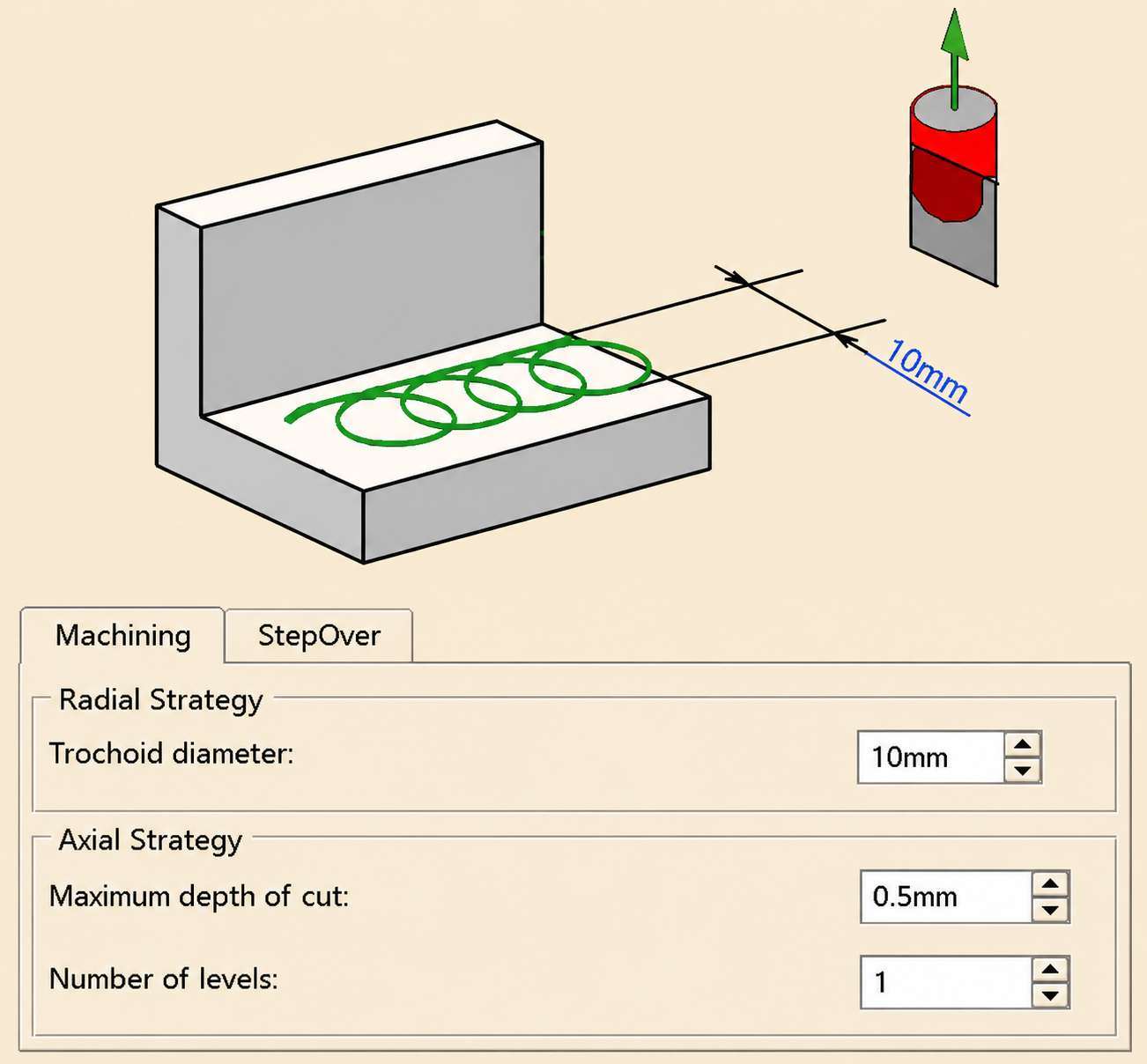
Trochoid Milling (CATIADOC)
Trochoidal milling is a CNC machining strategy that removes material through overlapping circular toolpaths while maintaining a limited radial cutter engagement throughout the cutting cycle.
Why Trochoidal Milling Is Used
Trochoidal milling is often chosen when conventional slotting becomes unstable or too hard on the tool. The looping motion keeps radial engagement relatively low, which makes force spikes less severe as the cutter enters corners or works through a deep cavity. Because the tool is not buried as heavily in the material, chips clear more freely and the cutting edge does not hold heat in the same way.
Shops usually notice the benefit most clearly when roughing stainless or other alloys that become difficult once heat and cutting pressure begin to build. In practice, the programmer sets the cutting limits in CAM, and the software generates the looping path from there.
How Trochoidal Milling Works
Trochoidal milling combines circular interpolation with continuous feed movement along the machining path.
Constant Radial Engagement
- The cutter enters the workpiece with a predefined radial stepover, commonly between 5% and 20% of the tool diameter.
- The CAM system maintains a nearly constant engagement angle as the cutter advances along the programmed path.
- The tool center follows the programmed X and Y coordinates while the cutter engagement remains relatively uniform.
- A consistent engagement angle reduces sudden load changes as the cutter passes through slots, pockets, and internal corners.
Circular Cutter Motion
- The cutter follows overlapping circular arcs while simultaneously advancing in the feed direction.
- X-axis and Y-axis movements combine to generate the continuous trochoidal path across the workpiece.
- Each circular loop removes a small section of material before the tool progresses to the next cutting location.
- The programmed path gradually clears the complete machining area without full-width cutter engagement.
Stable Chip Formation and Heat Control
- The limited engagement angle produces a more uniform chip thickness throughout each cutter rotation.
- Chips exit the cutting zone after every circular pass, reducing chip recutting during machining.
- Heat is distributed over a larger portion of the cutting edge rather than concentrated at a single contact point.
- Stable cutting conditions help reduce tool deflection during long roughing operations.
Advantages and Limitations of Trochoidal Milling
Trochoidal milling maintains a relatively constant cutter engagement throughout most of the machining cycle. The strategy can reduce cutting loads during roughing operations, although it also requires suitable programming and machine capability. The final choice depends on the part geometry, material, cutting tool, and production objective.
Lower Cutting Forces
The cutter removes material with a small radial stepover instead of cutting across its full diameter. Because the engagement angle changes very little, cutting forces remain more consistent throughout the toolpath. Long slots and deep pockets usually benefit the most from this cutting strategy because the tool enters fewer heavy-cutting conditions.
Longer Tool Life and Better Heat Control
Each cutting edge spends less time in contact with the workpiece during one revolution. Chips leave the cutting zone more freely, carrying a large portion of the cutting heat away from the tool. Instead of concentrating wear on one area of the cutter, the cutting load is distributed more evenly along the cutting edges.
Higher Programming Complexity
- Trochoidal toolpaths are generated automatically by CAM software using the selected machining strategy.
- Feed rate, radial stepover, cutting depth, and cutter engagement should be configured together before toolpath generation.
- Circular radius and stepover determine the spacing and overlap between successive cutter loops.
- Review the generated toolpath for unnecessary air cutting before post-processing the NC program.
- Adjust machining parameters if the toolpath produces abrupt direction changes, excessive retracts, or inefficient cutter movement.
Whether trochoidal milling improves efficiency depends on the part as much as the toolpath. Deep enclosed pockets, material type, machine rigidity, and production volume all influence whether this strategy offers a practical advantage. During quotation, JLCCNC reviews these factors alongside the CAD model to determine an appropriate machining approach before production begins.

Precision CNC Machining Service
Professional manufacturing, fast turnaround, and quality assurance.
Situations Where Trochoidal Milling Is Not Ideal
Trochoidal machining is not suitable for every operation. In several situations, a conventional toolpath produces a shorter cycle time or a simpler machining process.
- Face milling large flat surfaces because straight toolpaths remove material more directly with fewer machine movements.
- Light finishing operations since finishing requires a stable surface quality and accurate final dimensions, rather than aggressive stock removal.
- Shallow pockets with limited stock because the additional circular motion provides little machining advantage.
- Simple open profiles that can be machined efficiently with standard contour milling or pocket milling cycles.
- Older CNC machines with limited look-ahead capability, as frequent changes in tool direction can reduce feed consistency and increase cycle time.
- Parts with limited machining clearance, especially when the circular cutter path cannot be completed without contacting adjacent features or walls.
Trochoidal Milling vs Conventional Milling
Both machining strategies remove the same material, but the cutter follows a different path. Conventional milling relies mainly on linear passes, whereas trochoidal milling generates overlapping circular arcs throughout the cut.
This difference influences cutter engagement, spindle load, machining time, and tool wear during roughing operations.
Tool Engagement and Cutting Forces
Conventional milling can expose the cutter to large changes in engagement, particularly during full-width slotting and internal corners. These changes increase cutting forces as more of the cutter enters the material. Trochoidal milling limits radial engagement throughout the toolpath, producing a steadier cutting load and reducing sudden force changes. This difference becomes more noticeable during deep slots and difficult-to-machine materials.
Heat Generation and Tool Wear
Heat builds more quickly during conventional milling because a larger section of the cutter remains engaged with the workpiece. Higher cutting temperatures can accelerate edge wear, especially during long roughing operations. Trochoidal milling spreads the cutting load over more of the cutting edge and gives the tool additional time to cool between engagements. Chips also leave the cutting zone more easily, reducing heat accumulation around the cutter.
Choosing the Right Milling Strategy
Select trochoidal milling if the operation includes:
- Deep slots that keep the cutter engaged for a long cutting distance.
- Narrow pockets with limited space for chip evacuation.
- Stainless steel, titanium, tool steel, and other materials that generate high cutting loads.
- Heavy roughing operations that remove a large volume of material before finishing.
- Small-diameter end mills that benefit from lower radial engagement.
Select conventional milling if the operation includes:
- Face milling and other large open surfaces.
- Light roughing with shallow depths of cut.
- Finishing passes that require the final surface finish and dimensional accuracy.
- Simple profiles that can be machined with straight toolpaths.
- Features that do not require continuous circular cutter motion.
Feeds, Speeds, and Cutting Parameters
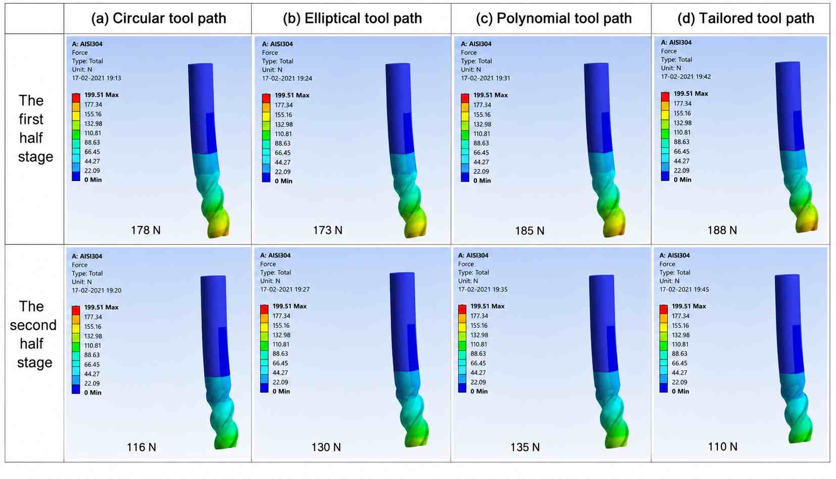
Trochoidal milling tool path tailoring based on curvature variation (ScienceDirect)
Trochoidal milling depends on a balanced combination of cutting parameters. Feed rate, spindle speed, radial engagement, and axial depth should be adjusted together because each value changes the cutter load during the machining cycle.
Feed Rate and Spindle Speed
Because radial engagement is intentionally small, radial chip thinning often occurs. Feed rates are therefore frequently increased to maintain the desired chip load, provided machine rigidity, spindle power, and tool stability allow it.
- Start with the cutting data recommended by the tool manufacturer.
- Increase the feed only after confirming stable chip formation.
- Avoid reducing the feed excessively at high spindle speeds because the cutter may begin rubbing instead of cutting.
- Verify spindle power before increasing both feed rate and cutting depth.
Radial Width of Cut
- Most trochoidal toolpaths are programmed with a radial engagement between 5% and 20% of the cutter diameter.
- Larger stepovers increase cutter engagement and spindle load throughout the toolpath.
- Smaller stepovers reduce cutter load but extend the total machining distance.
- Select the stepover according to the cutter diameter and the amount of stock to remove.
Axial Depth of Cut
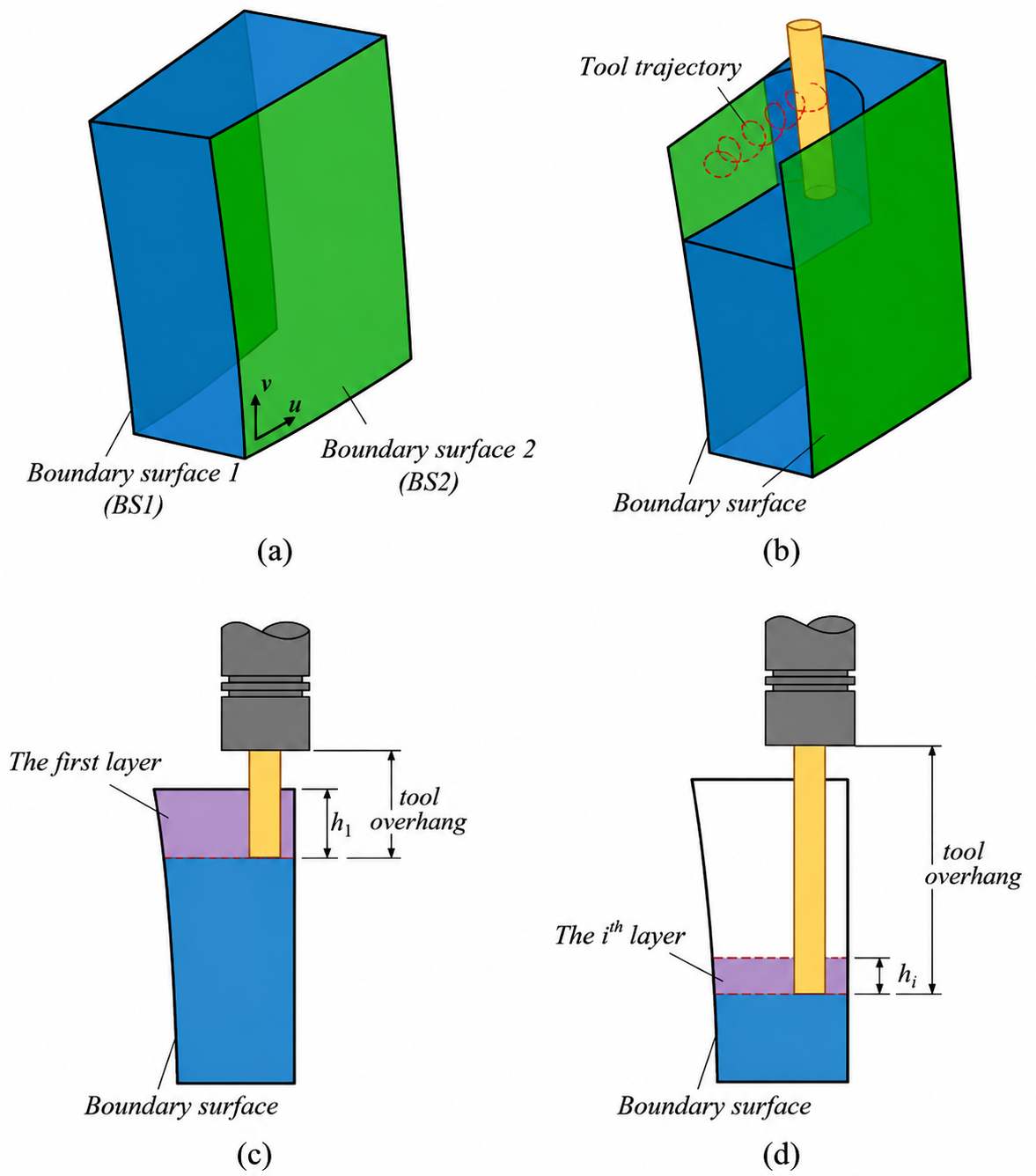
A variable-depth multi-layer five-axis trochoidal milling method for machining deep freeform 3D slots (ScienceDirect)
- The cutting depth should remain within the usable flute length.
- Deep cuts require a rigid holder, short tool overhang, and secure workholding.
- Reduce the cutting depth if vibration appears during roughing.
- Leave a small amount of stock for the finishing operation instead of machining to the final dimension in one pass.
Balancing Productivity and Tool Life
- Increase material removal by combining moderate changes to several cutting parameters instead of one large adjustment.
- Review tool wear after the first production run and refine the machining data if necessary.
- Stable cutting conditions usually produce more predictable tool life than aggressive machining parameters.
- Record proven cutting parameters so the same toolpath can be reused for future production batches.
| Cutting Parameter | Primary Effect on Machining | If Too Low | If Too High |
|---|---|---|---|
| Feed Rate (F) | Controls chip load and material removal per revolution. | Chips become too thin, increasing rubbing and heat generation. | Cutting forces increase, leading to higher tool wear and possible tool deflection. |
| Spindle Speed (RPM) | Determines cutting speed at the tool edge. | Lower cutting speed can reduce productivity and affect surface quality. | Excessive heat develops at the cutting edge, accelerating wear. |
| Radial Width of Cut (Ae) | Controls cutter engagement and engagement angle. | Material removal rate decreases because each pass removes less stock. | Higher engagement increases cutting forces and reduces the advantage of trochoidal milling. |
| Axial Depth of Cut (Ap) | Defines the cutting depth along the Z-axis. | More machining passes are required to reach the final depth. | Tool deflection, vibration, and spindle load increase if rigidity is insufficient. |
| Chip Load (Fz) | Determines the material removed by each cutting edge. | The cutter rubs instead of cutting efficiently, generating unnecessary heat. | The cutting edge carries excessive load, increasing the risk of chipping and breakage. |
| Tool Engagement Angle | Influences the cutting force distribution during the toolpath. | The cutter removes less material per pass, extending cycle time. | Higher engagement produces larger force variations, especially in corners and narrow slots. |
| Tool Overhang | Affects cutter stiffness and machining stability. | Short overhang provides greater rigidity and stable cutting conditions. | Long overhang increases vibration, tool deflection, and dimensional variation. |
| Coolant or Air Blast | Removes heat and clears chips from the cutting zone. | Chips may accumulate around the cutter, increasing recutting. | Excessive coolant pressure is generally unnecessary if chip evacuation is already effective. |
Trochoidal Milling Programming
Most trochoidal toolpaths are created in CAM software rather than programmed manually. The programmer selects the machining feature, cutting tool, and machining parameters, while the software calculates the circular cutter motion. Before the NC program reaches the machine, the complete toolpath should be reviewed to confirm that the cutter moves safely through the workpiece.
Adaptive Toolpath Strategies
The CAM system generates the toolpath by maintaining a controlled cutter engagement instead of following a simple straight pass. Radial stepover, cutting depth, feed rate, and engagement angle work together to produce the final cutter motion. These values should be checked together because changing one parameter affects the complete toolpath.
Entry, Exit, and Linking Moves
The cutter normally enters the material with a ramp, helix, or circular lead-in instead of a direct vertical plunge. Linking moves connect one cutting path to the next while keeping unnecessary air cutting to a minimum. A smooth entry and exit path also reduces sudden cutter loading at the beginning and end of each machining pass.
Toolpath Simulation and Verification
Run the complete simulation before sending the program to the CNC machine. Verify cutter engagement, rapid movements, entry points, retract heights, and tool clearance around the workpiece and fixtures. The simulation should also confirm that the remaining stock matches the machining strategy and that no uncut material remains in deep pockets, corners, or narrow slots.
Designing Parts for Trochoidal Milling
Designing parts for trochoidal machining begins with understanding how the cutter moves through the feature. Features that match the cutter size and support continuous tool movement are generally easier to machine. Reviewing these details during the design stage can reduce programming changes after the CAD model reaches manufacturing.
Pocket Geometry
The pocket width should provide enough space for the cutter to complete its circular motion. Very narrow pockets restrict the toolpath and reduce the benefit of trochoidal milling. Deep pockets should also provide adequate clearance for chip evacuation during roughing.
Tool Accessibility
Every machined feature should be accessible with a standard end mill whenever practical. Deep cavities, narrow openings, and long tool overhangs reduce tool rigidity and increase cutter deflection. A shorter, more rigid tool generally produces better cutting conditions.
Corner Radius Design
Internal corner radii should match the cutter size instead of specifying sharp corners. A suitable corner radius allows the cutter to maintain a smoother toolpath without slowing significantly at each corner. It also reduces unnecessary secondary machining operations.
Feature Layout for Continuous Toolpaths
Features that share a similar machining direction are easier to connect with one continuous toolpath. Reducing isolated pockets, unnecessary walls, and abrupt direction changes simplifies the machining sequence. A continuous toolpath also reduces retract movements and non-cutting machine travel between features.
Common Applications of Trochoidal Milling
Trochoidal milling is selected for operations that place a high load on the cutter during conventional milling. Features with limited cutting space, greater cutting depth, and difficult materials generally gain the most from this strategy because the cutter engagement remains more consistent throughout the toolpath.
Deep Slots and Narrow Pockets
Deep slots keep the cutter engaged for most of the machining cycle, making them difficult to machine with full-width cuts. Trochoidal milling removes material in small circular passes, reducing cutter load as the tool progresses through the slot. The same approach works well for narrow pockets that leave little room for chip evacuation.
Hard Materials
Materials such as hardened steel, tool steel, stainless steel, titanium, and nickel alloys generate high cutting loads during roughing. Trochoidal toolpaths maintain a lower radial engagement, reducing the force applied to the cutting edge throughout the machining cycle. This approach also produces more consistent cutting conditions across long machining operations.
Thin-Wall Components
Thin walls can deflect if excessive cutting force is applied during roughing. Trochoidal milling reduces the amount of material engaged by the cutter at one time, limiting the force transferred to the remaining wall. Many programmers leave a small amount of stock for a separate finishing pass after roughing is complete.
High-Efficiency Roughing
Large amounts of stock can be removed through multiple deep passes instead of repeated full-width cuts. The cutter follows a continuous circular path while gradually clearing the remaining material. This strategy is commonly programmed before semi-finishing and finishing operations because it prepares a more uniform stock condition for the remaining machining steps.
Conclusion About Trochoidal Milling
Trochoidal milling provides a practical roughing strategy for operations that involve deep slots, narrow pockets, and difficult-to-machine materials. By maintaining a controlled cutter engagement throughout the toolpath, the process reduces cutting force, distributes heat more evenly, and supports stable material removal across demanding machining operations.
Successful implementation depends on more than selecting a trochoidal toolpath. Tool selection, cutting parameters, workholding, and CAM programming all contribute to consistent machining results. Evaluating these factors during process planning helps produce a stable machining process and predictable part quality.
Trochoidal milling is only one part of the machining strategy. Cutter selection, workholding, machining sequence, and CAM programming all affect the final result. During quotation, JLCCNC reviews these factors together with the part geometry to determine an appropriate machining approach for the project.
If your design includes deep slots, narrow pockets, or difficult-to-machine materials, upload your CAD file for an engineering drawing review. JLCCNC evaluates the machining strategy and provides manufacturing feedback before production begins.
Precision CNC Machining Service
Professional manufacturing, fast turnaround, and quality assurance.
FAQ About Trochoidal Milling
Q: What is trochoidal milling?
Trochoidal milling is a CNC roughing strategy that removes material through overlapping circular toolpaths while maintaining a controlled cutter engagement. The approach reduces cutting force compared with conventional full-width milling.
Q: How does trochoidal milling differ from conventional milling?
Conventional milling often engages a larger portion of the cutter, particularly during slotting and corner machining. Trochoidal milling limits radial engagement throughout the toolpath, producing a more consistent cutting load.
Q: Is trochoidal milling the same as adaptive milling?
Not exactly. Trochoidal milling is a circular cutting strategy, while adaptive milling is a broader CAM strategy that adjusts the toolpath to maintain a consistent cutter load. Many CAM systems generate trochoidal-style movements within adaptive roughing operations.
Q: What materials benefit most from trochoidal milling?
Trochoidal milling is widely applied to stainless steel, titanium, tool steel, hardened steel, nickel alloys, and other materials that generate high cutting loads during roughing. It is also effective for aluminum parts containing deep slots and narrow pockets.
Q: How do feeds and speeds affect trochoidal milling?
Feed rate, spindle speed, radial engagement, and axial depth should be selected together. Changing one parameter influences chip load, cutter engagement, and cutting conditions throughout the machining cycle.
Q: How are trochoidal toolpaths programmed?
Most CAM systems generate trochoidal toolpaths automatically after the programmer selects the machining feature, cutting tool, and machining parameters. The completed toolpath is then verified through simulation before post-processing.
Q: Does trochoidal milling improve tool life?
It often extends tool life during roughing because the cutter operates with a more consistent engagement and lower cutting force. The final result still depends on the cutting tool, machining parameters, workpiece material, and machine stability.
Q: When should trochoidal milling be used?
Trochoidal milling is a practical choice for roughing deep slots, narrow pockets, difficult materials, and features that produce high cutter engagement during conventional milling. Simpler features and finishing operations generally use different machining strategies.
Q: What is the difference between trochoidal milling and high-efficiency milling (HEM)?
Trochoidal milling is a specific toolpath strategy that removes material through overlapping circular motions while maintaining a relatively low radial engagement. High-efficiency milling (HEM) is a broader machining approach focused on maintaining a consistent cutter load and increasing material removal efficiency.
Many modern CAM systems implement HEM using trochoidal-style or adaptive toolpaths where appropriate, but they may also adjust the toolpath automatically to suit changing geometry. For that reason, trochoidal milling is often viewed as one toolpath strategy within the broader HEM approach rather than a completely separate machining process.
Keep Learning
Laser Engraving Aluminum: Marking Methods & Surface Effects
Key Takeaways Laser engraving usually removes base material to create a recess. Laser marking is a broader term that can describe a surface-color change or material removal, so the process name alone does not define the final result. On aluminum, alloy and surface finish affect marking contrast. A light mark on dark anodized aluminum is a common design target, but the actual appearance depends on the finish and laser process. JLCCNC laser marking produces a recessed area 0.03–0.1 mm deep. The result i......
CNC Cutting Fluid: Types, Functions, Applications, and Selection Guide
Key Takeaways Cutting fluid in machining performs four functions simultaneously: cooling the tool and workpiece, lubricating the tool-chip interface to reduce friction, carrying chips away from the cut zone, and protecting machined surfaces from corrosion between operations. Different machining operations need different fluid priorities: high-speed aluminum milling may need adhesion control and chip evacuation, threading and tapping need strong lubrication, and grinding requires both cooling and fine ......
Blind Hole Machining Guide: What Is a Blind Hole, Types of Holes, and Tapping Tips
What Is a Blind Hole? Types of Holes and CNC Hole Machining Explained In CNC machining, few operations challenge process control and tool stability as much as blind hole machining. A blind hole is a hole that terminates at a defined internal depth rather than breaking through the opposite surface. Because the cavity is enclosed at the bottom, chip evacuation, thermal behavior, tool wear, and dimensional accuracy become far more difficult to manage compared to through-hole machining. These constraints ......
Rake Angle in Machining: Machinists’ Guide to Perfect Cuts
What is Rake Angle? (minaprem) If you've ever stood in front of a CNC machine or a manual lathe, you know that the cutting tool's geometry isn't just some arbitrary design. Every angle, edge, and surface has a job to do, and one of the most important of those is the rake angle. We've been running machines long enough to know that rake angle can make or break your surface finish, tool life, and machining efficiency. In this guide, we're going to walk you through what rake angle is, how it works, and ho......
Sheet Metal vs CNC Machining: A Guide to Choosing the Right Method for Your Metal Parts
Quick Answer: Choose sheet metal for uniform-thickness enclosures, panels, and formed brackets when bends and production volume support lower unit cost. Choose CNC machining for variable wall thickness, precision bores, tight feature relationships, and complex 3D geometry. Use a hybrid design when a formed structure needs precision-machined interfaces. A quote comes back for a bracket, and it's priced as a CNC part — machined from solid aluminum, a few hours of spindle time, a per-part cost that makes......
What Steps Are Taken To Minimize Waste In CNC Machining Processes?
How to Reduce Waste in CNC Machining: 5 Practical Strategies Quick Answer: CNC machining waste is reduced mainly through DFM, near-net stock, efficient toolpaths, preventive tool maintenance, and alloy-segregated recycling. The biggest gains usually come before cutting: reduce unnecessary material removal and prevent scrap or rework. Every CNC-machined part starts as more material than it ends up being. A pocket gets milled out, a profile gets cut away, a boss gets faced down to size — and all of that......