What Is Tool Offset in CNC? Types, Setup & Best Practices
8 min
- What Is Tool Offset in CNC Machining?
- Types of Tool Offsets
- How Tool Offsets Work During Machining
- Setting and Verifying Tool Offsets
- Common Tool Offset Errors and Troubleshooting
- How Tool Offsets Affect Machining Accuracy
- Best Practices for Tool Offset Management
- FAQs about Tool Offset
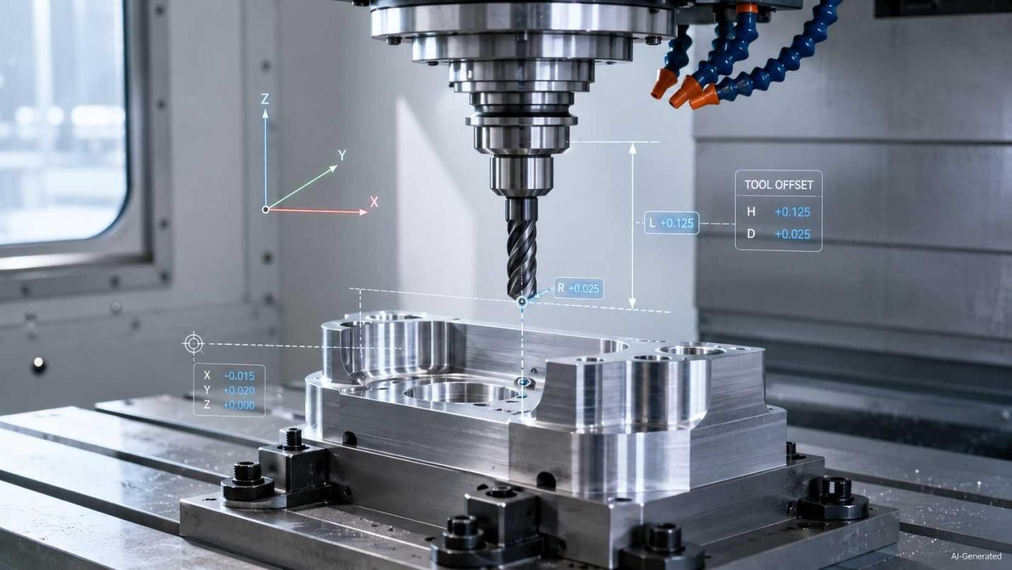
CNC tool offset setup with measurement overlay
Key Takeaways
- CNC offsets connect programmed intent with actual cutter position.
- Length data guides Z-axis depth control.
- Radius data protects part size during contour milling.
- Geometry values define the cutter's measured baseline.
- Wear values support fine correction during production.
- Verified data lowers scrap risk before full machining.
- Good offset habits protect tools, fixtures, and parts.
In the context of CNC machining , tool offset is the quiet setup detail that decides whether a programmed path becomes an accurate part. Before feeds, speeds, or cycle time matter, the control needs trusted cutter data to place each edge where the drawing expects it.
What Is Tool Offset in CNC Machining?
A tool offset is a saved correction value inside the CNC control that tells the machine where the cutter's working edge or tip is relative to the programmed position.
Why CNC Machines Need Offsets
No two cutters enter the spindle with identical reach, diameter, tip shape, holder projection, or cutting behavior. So, the control needs numerical correction before metal removal starts.
Programmed Toolpath vs Compensation Data
The programmed toolpath describes the intended motion. Compensation data allows the control to shift that motion to match the cutter mounted in the machine.
Types of Tool Offsets
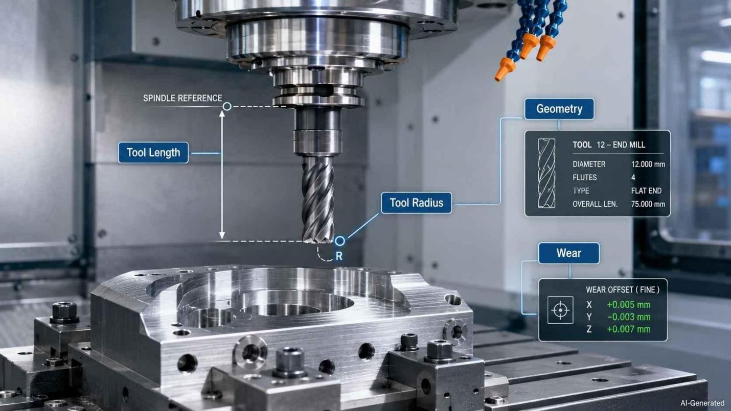
Types of CNC tool offsets shown on milling setup
Tool Length Offset
Tool length offset handles the distance from a spindle reference face to the cutter tip. It lets different holders and projections share one Z program without redrawing the operation. G43 is the common CNC code for positive tool length compensation.
Tool Radius Offset
Tool radius offset covers the edge width in X/Y milling. The control uses radius or diameter data for profile walls, pockets, and shoulders. G41 positions the cutter to the left of the programmed toolpath, while G42 positions it to the right.
Geometry Offset
On many CNC controls, geometry offsets store the tool's measured baseline dimensions, such as length, diameter, nose radius, or orientation, before any wear compensation is applied.
Wear Offset
Wear offset stores small corrections applied after machining begins to compensate for gradual tool wear or thermal effects.
How Tool Offsets Work During Machining
Applying Tool Length Compensation
After a tool is called, the control reads the corresponding H offset and adjusts the Z-axis position to match the actual tool length. Meanwhile, the H-code tells the control which tool length register to read.
Applying Cutter Radius Compensation
When it comes to side cutting, codes such as G41 or G42 inform the control about placing the cutter left or right of the programmed contour using the stored cutter radius. Note that some controls store cutter compensation values in D-word records.
Updating Wear Compensation During Production
In the event that the inspection reveals a shifting bore, slot, or wall, the operator might modify the wear field for the offset tool and bring the size closer to the nominal value.
For parts with tight dimensional requirements, correct tool offset management is only one part of the machining process. JLCCNC reviews machining strategy before production to help reduce setup-related errors.

Precision CNC Machining Service
Professional manufacturing, fast turnaround, and quality assurance.
Setting and Verifying Tool Offsets
Measuring Tool Dimensions
Tool length and diameter are measured with a tool setter, presetter, probe, or height gauge before machining begins.
Entering Offset Values
The measured tool length or diameter is entered into the corresponding offset register in the CNC control.
Verifying Offsets Before Machining
Before cutting material, verify the setup with a dry run, single-block execution, a safe Z approach, and the distance-to-go display.
Confirming Offsets With Probing or Test Cuts
After a probe cycle or trial cut confirms the expected size and tool position, the offset can be released for production.
Common Tool Offset Errors and Troubleshooting
Incorrect Offset Values
A bad or incorrect number shows up as shallow cuts, oversize pockets, tapered features, or a sudden gouge. Typically, the trail leads back to measurement, sign, or unit entry. Even a 0.05 mm offset error can shift the machined feature by approximately the same amount.
Using the Wrong Offset Register
When the program calls one register and the operator edits another, the machine follows old data. It reveals the mismatch through one affected cutter rather than every station.
Offset Errors After Tool Changes
After an insert, holder, or cutter swap, the saved data might no longer match the new cutting edge. It leaves the first machined feature as the warning sign.
Wear Offset Not Updated
Because a drifting bore, slot, or wall is often an indication of tool wear, the CNC tool offset record is the first place to evaluate once an inspection has been completed.
How Tool Offsets Affect Machining Accuracy
Compensating for Tool Variation
Every cutter enters the spindle with its own length, edge radius, coating thickness, and holder projection. A well-kept tool offset treats those differences as usable control data.
Maintaining Dimensional Accuracy
Slots, shoulders, bores, and depths are brought closer to the print using cutter data that has been corrected. As a result, it reduces inspection shocks across the first part and the last part.
Improving Repeatability
When the same offset record is used consistently, operators can compare inspection readings, trace drift, and adjust with far less trial work.
Supporting Stable Production
Accurate offset control also protects surface finish and edge life. In this situation, the cutter removes the intended amount of material instead of rubbing, gouging, or overcutting.
Best Practices for Tool Offset Management
Standardizing Tool Measurement Procedures
Use the same tool setter, probing procedure, contact point, and naming convention throughout each shift. After that, make a note of who measured the tool and when they did so.
Maintaining Accurate Tool Libraries
Keep each library entry current with cutter type, holder, projection, nose data, flute count, and approved use. It provides programmers and operators with one trusted reference.
Reviewing Offset Data After Tool Changes
Once a cutter swap happens, compare the new value against the last approved record. Investigate any unexpected change before machining resumes.
Integrating Offsets With Probing and Process Control
Link offset records with probing results and inspection data so drift can be detected before it affects production.
FAQs about Tool Offset
Q: What is tool offset in CNC?
Tool offset is a stored compensation value that allows the CNC control to position the cutting tool correctly relative to the programmed toolpath or workpiece.
Q: What is the difference between tool length and tool radius offset?
Length data affects Z depth. Radius data affects side position during milling contours.
Q: What is wear offset?
Wear offset is a small adjustment applied after inspection to compensate for tool wear without changing the main tool geometry offset.
Q: What is G43 in CNC?
G43 enables positive tool length compensation on most CNC milling controls. After a tool is called, the control reads the specified H offset and adjusts the Z-axis position to account for the tool's actual length. This allows tools with different lengths to use the same programmed toolpath while maintaining the correct cutting depth.
Q: What is an H offset in CNC?
An H offset identifies the tool length offset register used by the control. When G43 is called, the CNC reads the specified H value to compensate for the actual tool length.
Q: How are tool offsets measured?
Operators measure with a presetter, touch probe, height gauge, tool setter, or controlled trial cut.
Q: Why are tool offsets important?
Tool offsets allow the CNC machine to position each cutting edge correctly, helping maintain dimensional accuracy and reducing setup errors.
Q: How often should tool offsets be updated?
After every measurable size shift, tool replacement, insert indexing, first-piece inspection, thermal drift, or any other kind of change, they should be updated.
Q: Can CNC probing automatically update tool offsets?
Yes. Probe macros can automatically measure a cutter and update the corresponding offset registers.
Q: What is the difference between tool offsets and work offsets?
Tool offsets define the cutter geometry, while work offsets define the location of the workpiece coordinate system relative to the machine coordinate system.
Q: How do tool offsets affect machining accuracy?
Accurate tool offsets keep the cutting edge in the intended position, improving dimensional accuracy and reducing variation between parts.
Precision CNC Machining Service
Professional manufacturing, fast turnaround, and quality assurance.
Conclusion About Tool Offset
Tool offsets are established before machining begins, but they influence every operation that follows. Correct offset data helps the machine reproduce the intended toolpath with fewer setup corrections and more consistent machining results. Before production, JLCCNC reviews each project to confirm that the machining strategy matches the part requirements.
Upload your CAD file to receive a quotation and DFM review from JLCCNC before production.
Keep Learning
Laser Engraving Aluminum: Marking Methods & Surface Effects
Key Takeaways Laser engraving usually removes base material to create a recess. Laser marking is a broader term that can describe a surface-color change or material removal, so the process name alone does not define the final result. On aluminum, alloy and surface finish affect marking contrast. A light mark on dark anodized aluminum is a common design target, but the actual appearance depends on the finish and laser process. JLCCNC laser marking produces a recessed area 0.03–0.1 mm deep. The result i......
CNC Cutting Fluid: Types, Functions, Applications, and Selection Guide
Key Takeaways Cutting fluid in machining performs four functions simultaneously: cooling the tool and workpiece, lubricating the tool-chip interface to reduce friction, carrying chips away from the cut zone, and protecting machined surfaces from corrosion between operations. Different machining operations need different fluid priorities: high-speed aluminum milling may need adhesion control and chip evacuation, threading and tapping need strong lubrication, and grinding requires both cooling and fine ......
Blind Hole Machining Guide: What Is a Blind Hole, Types of Holes, and Tapping Tips
What Is a Blind Hole? Types of Holes and CNC Hole Machining Explained In CNC machining, few operations challenge process control and tool stability as much as blind hole machining. A blind hole is a hole that terminates at a defined internal depth rather than breaking through the opposite surface. Because the cavity is enclosed at the bottom, chip evacuation, thermal behavior, tool wear, and dimensional accuracy become far more difficult to manage compared to through-hole machining. These constraints ......
Rake Angle in Machining: Machinists’ Guide to Perfect Cuts
What is Rake Angle? (minaprem) If you've ever stood in front of a CNC machine or a manual lathe, you know that the cutting tool's geometry isn't just some arbitrary design. Every angle, edge, and surface has a job to do, and one of the most important of those is the rake angle. We've been running machines long enough to know that rake angle can make or break your surface finish, tool life, and machining efficiency. In this guide, we're going to walk you through what rake angle is, how it works, and ho......
Sheet Metal vs CNC Machining: A Guide to Choosing the Right Method for Your Metal Parts
Quick Answer: Choose sheet metal for uniform-thickness enclosures, panels, and formed brackets when bends and production volume support lower unit cost. Choose CNC machining for variable wall thickness, precision bores, tight feature relationships, and complex 3D geometry. Use a hybrid design when a formed structure needs precision-machined interfaces. A quote comes back for a bracket, and it's priced as a CNC part — machined from solid aluminum, a few hours of spindle time, a per-part cost that makes......
What Steps Are Taken To Minimize Waste In CNC Machining Processes?
How to Reduce Waste in CNC Machining: 5 Practical Strategies Quick Answer: CNC machining waste is reduced mainly through DFM, near-net stock, efficient toolpaths, preventive tool maintenance, and alloy-segregated recycling. The biggest gains usually come before cutting: reduce unnecessary material removal and prevent scrap or rework. Every CNC-machined part starts as more material than it ends up being. A pocket gets milled out, a profile gets cut away, a boss gets faced down to size — and all of that......