Chip Thinning in CNC Machining: Formula, Feed Rate & Calculator
11 min
- What Is Chip Thinning?
- How Chip Thinning Works
- Chip Thinning Formula and Feed Rate Calculation
- Practical Chip Thinning Example
- Using a Chip Thinning Calculator
- Benefits of Chip Thinning
- When Should Chip Thinning Be Used?
- How to Apply Chip Thinning in CNC Machining
- Common Chip Thinning Mistakes
- Chip Thinning vs Conventional Milling
- FAQs About Chip Thinning
Key Takeaways
- Chip thinning lowers actual chip thickness at narrow radial engagement.
- Feed per tooth must rise to maintain the intended cutting load.
- The formula connects cutter diameter, stepover, and engagement geometry.
- A calculator applies the correction before feed-rate programming.
- The method suits partial-width cuts rather than full-width slotting.
Chip thinning takes place when a cutter takes a narrow stepover in order to make each chip thinner than the programmed chip load suggests. Understanding this effect allows programmers to select feed rates that maintain the intended chip load.
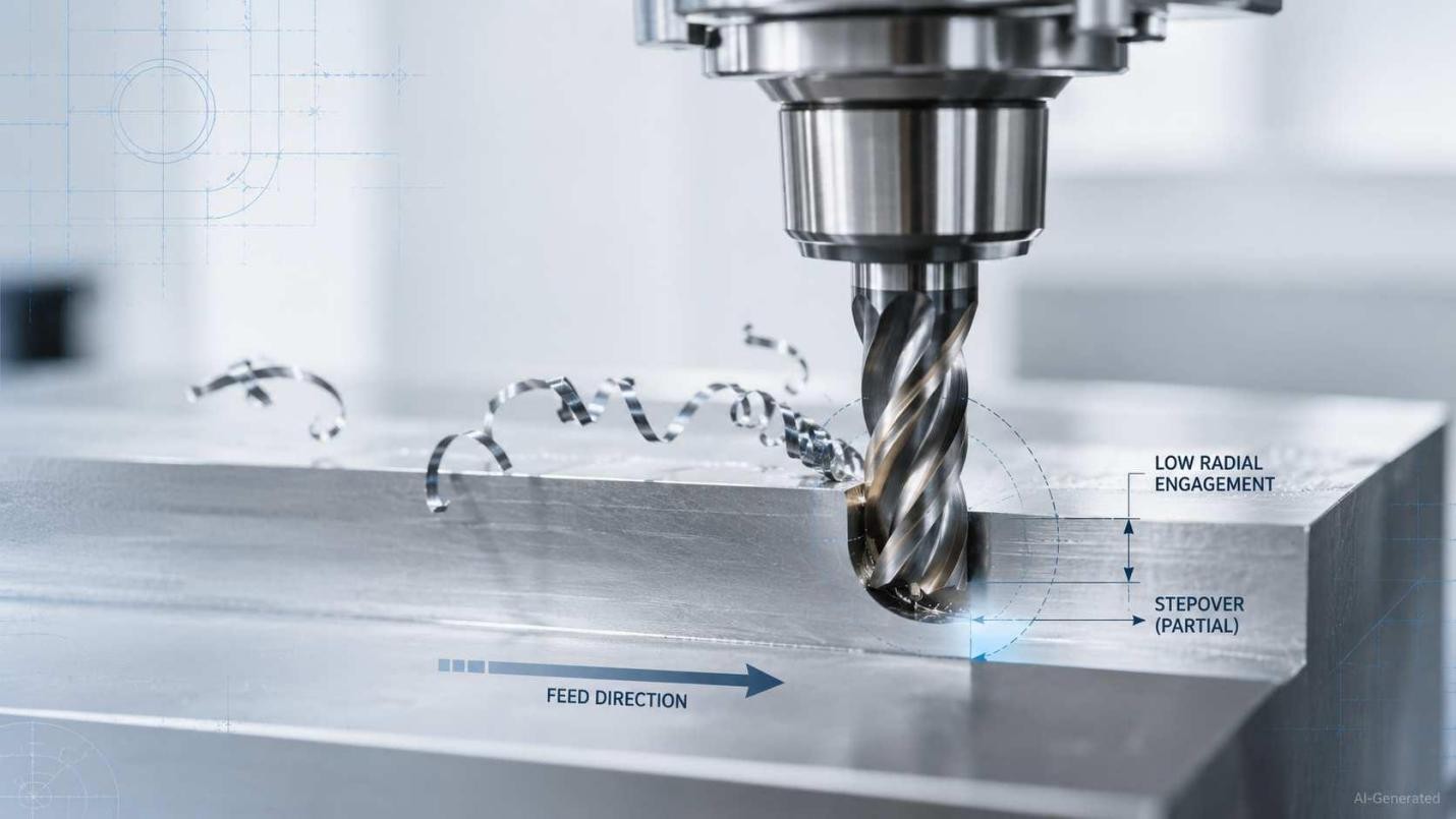
CNC milling with low radial engagement and thin chips
What Is Chip Thinning?
Essentially, chip thinning occurs when limited radial engagement makes the maximum undeformed chip thickness lower than the programmed feed per tooth.
Chip Thickness During Cutter Rotation
As each tooth follows its circular path, chip thickness varies across the engagement arc. A narrower stepover reduces the maximum thickness reached during contact.
Actual Chip Thickness vs Programmed Chip Load
Programmed chip load defines the feed advance of each cutting edge each time it engages the workpiece. But actual thickness shows the material removed. Under low radial engagement, chip thinning makes the latter smaller.
How Chip Thinning Works
Radial Engagement and Cutter Engagement Angle
Radial engagement compares the stepover with cutter diameter. As this ratio falls, the contact arc narrows. Moreover, each tooth spends fewer degrees inside the material.
How Chip Formation Changes
Because the engagement arc is shorter, the tooth leaves the material before reaching the programmed maximum chip thickness.
Why Chip Thinning Occurs
During peripheral milling, each cutting edge enters the workpiece with zero chip thickness. As the tooth rotates through the engagement arc, chip thickness increases to a maximum value before decreasing back to zero when the cutting edge exits the material. When radial engagement is reduced, the cutter remains in contact with the workpiece for a smaller engagement angle. The tooth leaves the material before the chip can reach the thickness expected from the programmed feed per tooth. Although the machine still advances the tool by the programmed feed, the maximum undeformed chip thickness becomes smaller because less of the cutter rotation is engaged in cutting.
The programmed feed per tooth remains unchanged. What changes is the maximum undeformed chip thickness created during each tooth engagement.
This geometric effect explains why feed compensation is required during low-radial-engagement milling. Increasing feed per tooth restores the target chip thickness rather than increasing the cutting load beyond the tool manufacturer's recommendation. The adjustment is commonly applied in high-efficiency milling, where radial engagement may be only 5% to 20% of the cutter diameter while axial depth of cut remains relatively large.
Radial Chip Thinning vs Axial Chip Thinning
The chip thinning discussed in this guide refers to radial chip thinning, which occurs when radial engagement is small relative to cutter diameter. Because the cutter contacts the workpiece over a shorter engagement angle, the maximum undeformed chip thickness becomes smaller than the programmed feed per tooth.
Axial chip thinning is a different effect. It is associated with cutters that have a large lead angle, such as high-feed milling cutters. The inclined cutting edge spreads chip formation over a longer edge length, reducing chip thickness even when feed per tooth remains unchanged. Although both effects require feed compensation, their geometry and calculation methods are different.
Radial Chip Thinning vs Full-Width Milling
Radial chip thinning becomes increasingly significant as radial engagement decreases. Feed compensation is commonly considered once radial engagement falls below about 50% of the cutter diameter, although the exact threshold depends on the tooling and machining strategy. Full-width slotting engages about 180 degrees of the cutter and allows maximum thickness to reach the programmed chip load.
Chip Thinning Formula and Feed Rate Calculation
For a 90-degree peripheral cutter, chip thinning below 50% radial engagement follows:
hmax = 2fz√[(ae/D)(1 − ae/D)]
0 < ae ≤ D/2
The equation shows how a reduced width of cut lowers maximum chip thickness.
This relationship applies to radial chip thinning during peripheral milling and assumes a standard 90-degree cutter engagement geometry. Different cutter geometries or machining strategies may require alternative calculations.
Understanding the Variables
Here, hmax represents the maximum chip thickness, fz represents feed per tooth, ae is radial engagement, and D is cutter diameter. Remember that every length value must use the same unit.
Feed Rate Adjustment
When thinning chips occur, use the radial factor Kr for the required feed per tooth and table feed:
Kr = 2√[(ae/D)(1 − ae/D)]
fz,adj = ht/Kr
vf = n z fz,adj
Here, ht is target chip thickness, n is spindle speed, z is the effective tooth count, and vf is table feed.
Example Calculation
For D=10 mm, ae=1 mm, and ht=0.05 mm/tooth:
Kr = 2√[(1/₁₀)(1 − 1/₁₀)] = 0.60
fz,adj = 0.05/0.60 = 0.083 mm/tooth
With four teeth at 6,000 rpm:
vf = 6,000 × 4 × 0.083 ≈ 2,000 mm/min
The adjusted feed therefore maintains a target chip thickness of 0.05 mm at 10% radial engagement.
Practical Chip Thinning Example
Machining Conditions
A 12 mm, five-flute end mill runs at 8,000 rpm, with 0.90 mm radial engagement and a target thickness of 0.040 mm/tooth. The stepover equals 7.5% of cutter diameter.
Step-by-Step Calculation
The radial factor is 0.527, which makes the unadjusted maximum thickness 0.021 mm/tooth. A chip thinning calculator therefore recommends 0.076 mm/tooth.
Kr = 2√[(0.90/12)(1 − 0.90/12)] = 0.527
hmax = 0.040 × 0.527 = 0.021 mm/tooth
fz,adj = 0.040/0.527 = 0.076 mm/tooth
Feed Rate Before and After Chip Thinning
Before chip thinning compensation, table feed is 1,600 mm/min. The corrected setting reaches 3,037 mm/min, subject to tool, holder, material, and machine limits.
The appropriate feed adjustment depends on more than radial engagement alone. Tool geometry, workpiece material, machining strategy, and machine capability all influence the final cutting parameters. During process planning, JLCCNC evaluates these factors before machining begins. Upload your CAD file to receive a manufacturing review and CNC machining quote.

Precision CNC Machining Service
Professional manufacturing, fast turnaround, and quality assurance.
Using a Chip Thinning Calculator
Required Inputs
A chip thinning calculator needs cutter diameter, radial width of cut, target chip load, spindle speed, and cutting-edge count. Consistent units keep its output dependable.
Manual Calculator vs CAM Software
A manual tool returns one corrected feed value. CAM software can account for chip thinning through stored tool data, stepover, spindle speed, and changing cutter engagement along the path.
How to Verify Calculator Results
Check the entered stepover, recalculate feed per tooth from RPM and tooth count, review the toolpath for heavier corner engagement, and keep the setting within tool and machine limits.
Benefits of Chip Thinning
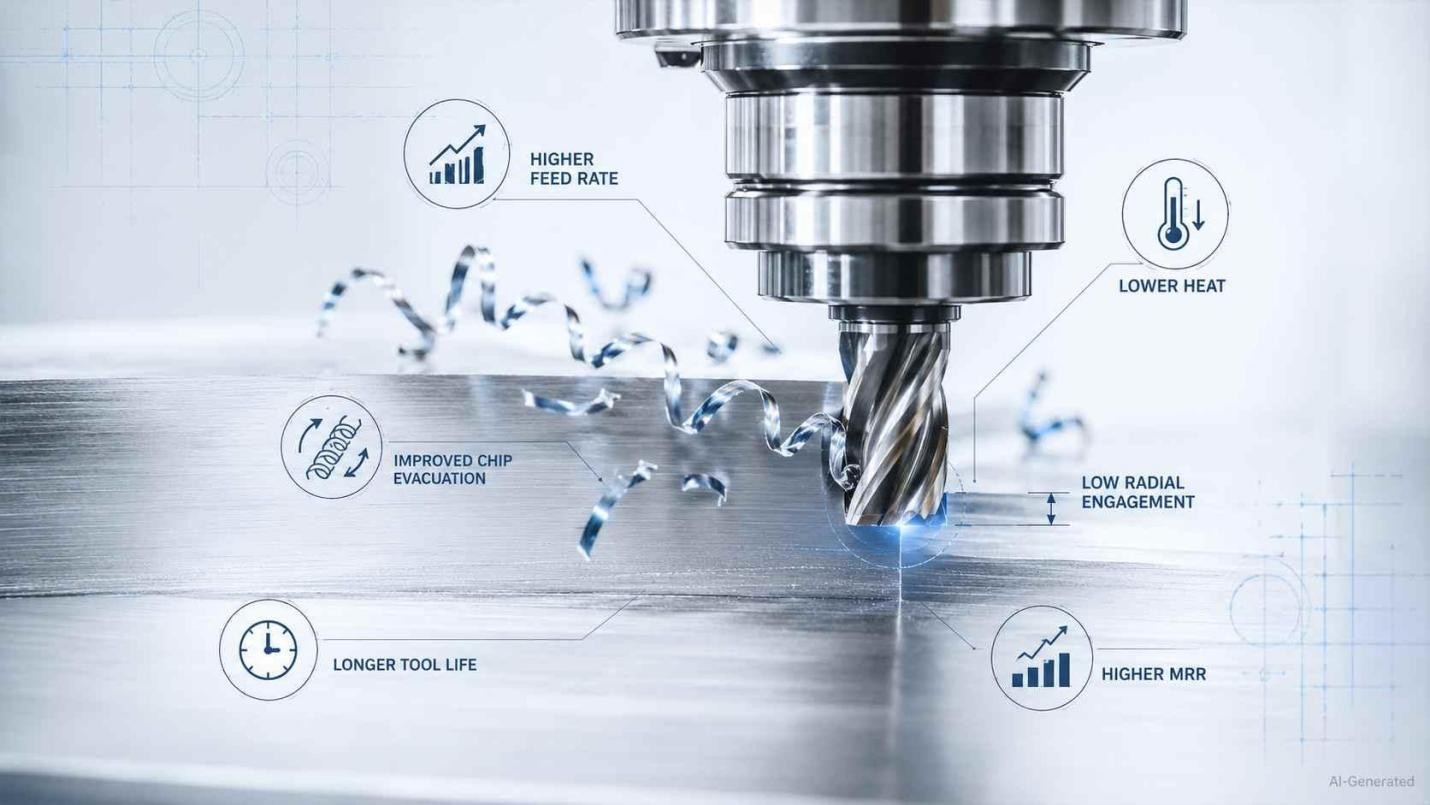
Benefits of chip thinning in CNC milling
Maintain the Recommended Chip Load
Appropriate chip thinning compensation preserves the intended undeformed thickness. Hence, this helps each edge shear material instead of rubbing or ploughing.
Increase Feed Rate Safely
With radial chip thinning, programmers may raise feed per tooth as engagement falls, after checking cutting force, spindle power, holder stability, and machine acceleration.
Reduce Heat and Extend Tool Life
Limiting temperature rise, reducing wear, and extending edge life is possible by limiting friction-dominated contact, which can be done by the appropriate chip thickness.
Increase Material Removal Rate
Material removal rate depends on radial engagement, axial depth of cut, and feed rate. Thus, an increase in the table feed that has been verified will boost output without widening the stepover.
When Should Chip Thinning Be Used?
Low Radial Engagement Milling
You should apply chip thinning when radial engagement becomes significant below approximately 50% radial engagement of cutter diameter. That is where a narrow contact arc might leave each edge underfed.
Adaptive and Trochoidal Toolpaths
Adaptive and trochoidal paths maintain low and uniform radial contact. This makes compensated feed appropriate for pockets, wider slots, and hard materials.
High-Efficiency Roughing
The same approach supports high-efficiency roughing, which combines shallow stepover with greater axial depth and elevated feed per tooth for productive material removal.
Situations Where Chip Thinning Should Not Be Used
Do not apply the chip thinning formula to full-width slotting, plunging, or paths with uncontrolled engagement. Use operation-specific cutting data and confirm equipment limits.
How to Apply Chip Thinning in CNC Machining
-
Calculate the Correct Feed Rate
Begin with target chip thickness, cutter diameter, and radial engagement. Calculate compensated feed per tooth, which is followed by table feed from spindle speed and active edge count.
-
Configure CAM Toolpaths
Enter the corrected cutting feed, set optimal load to the planned side engagement, and review the simulation for corners or re-entry moves that raise cutter contact.
-
Verify Machine Capability
With thinning chips, confirm that the higher programmed feed remains within axis acceleration, controller-processing, spindle-load, holder-grip, and tool limits.
-
Validate the Cutting Process
Run a cautious trial pass, monitor spindle load and chip evacuation, inspect edge wear, and approve the setting only after cutting remains stable.
Common Chip Thinning Mistakes
Applying Chip Thinning to Slot Milling
Slotting engages the cutter across its full diameter. It removes the low-radial-contact condition that supports chip thinning. Feed compensation here may overload the cutting edges.
Increasing Feed Rate Excessively
A chip thinning calculator supplies a geometric value, not permission to exceed tool, holder, spindle-power, or axis limits. Excessive feed may cause chatter, edge damage, or poor finish.
Ignoring Tool Deflection and Machine Rigidity
Long overhang, weak workholding, and limited stiffness magnify deflection under cutting force. It shifts dimensions and encourages vibration.
Using Identical Settings for Different Materials
Copying one setting across aluminum, steel, stainless steel, and heat-resistant alloys ignores material-specific cutting data, hardness, and engagement limits.
Chip Thinning vs Conventional Milling
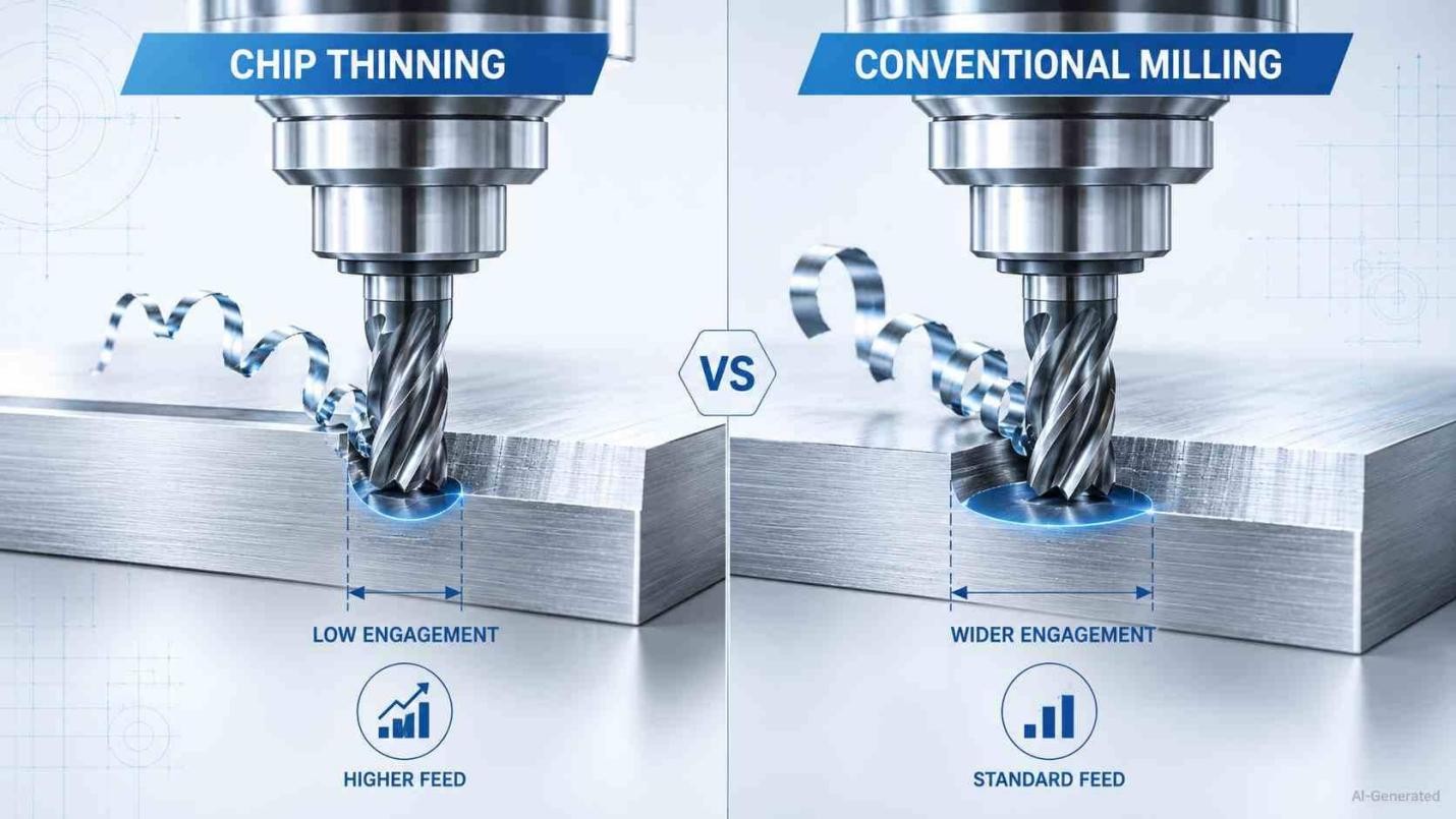
Chip thinning versus conventional CNC milling
Cutting Conditions Compared
Here, conventional cutting refers to a wider radial engagement rather than the up-milling direction. Low radial engagement creates a smaller engagement angle, producing the chip thinning effect. Wider cuts keep a larger portion of the cutter engaged with the workpiece.
Feed Rate and Chip Thickness
When thinning chips, programmers raise feed per tooth to preserve the intended thickness. Wider engagement needs less correction as each edge carries a larger section of material.
Which Strategy Should You Choose?
Choose low-engagement machining for adaptive, trochoidal, or high-efficiency roughing. Wider cuts are suitable for slotting and operations where equipment limits restrict elevated feed.
FAQs About Chip Thinning
Q: What is chip thinning?
When a milling cutter removes material via a small engagement arc, the actual chip thickness is reduced. This is what is meant by the term "chip thinning."
Q: Why does chip thinning occur?
Each tooth follows a circular path. Meanwhile, limited radial contact prevents the chip from reaching the thickness that is expected from programmed feed per tooth.
Q: What is radial chip thinning?
In situations when stepover, which is also referred to as radial depth of cut, is low in comparison to cutter diameter, this phenomenon is referred to as radial chip thinning.
Q: How is chip thinning calculated?
The calculation makes use of cutter diameter and radial engagement in order to find a geometric correction factor, which is applied to the target chip thickness.
Q: What is a chip thinning calculator?
When estimating compensatory feed per tooth and table feed, this tool takes into account the diameter, stepover, chip load, revolutions per minute (RPM), and tooth count variables.
Q: How does chip thinning affect feed rate?
Whenever the radial engagement decreases, the feed per tooth typically increases in order to keep the necessary or recommended average chip thickness consistently.
Q: Does CAM software calculate chip thinning automatically?
Some CAM systems automate compensation within supported toolpaths or optional settings. However, the programmer must review engagement and output values.
Q: When should chip thinning be applied?
The requirement for correction becomes more apparent when the cutter diameter is less than 50%. A greater adjustment is needed as the stepover decreases further.
Q: Can chip thinning improve tool life?
Absolutely. Reducing friction, controlling heat load, and ensuring a longer edge life are all possible outcomes of maintaining an appropriate chip thickness.
Q: Should chip thinning be used for slot milling?
The answer remains no. Full-width slotting has a significantly higher cutter engagement, which renders radial compensation unsuitable for the cutting condition.
Conclusion About Chip Thinning
Chip thinning works best as a controlled feed strategy and not as a blanket speed increase. Calculate from radial engagement, check the value against machine and tooling limits, and confirm it through chip shape, spindle load, surface quality, and edge wear. Used with that discipline, it supports productive milling without harming accuracy or tool reliability.
Precision CNC Machining Service
Professional manufacturing, fast turnaround, and quality assurance.
Keep Learning
Laser Engraving Aluminum: Marking Methods & Surface Effects
Key Takeaways Laser engraving usually removes base material to create a recess. Laser marking is a broader term that can describe a surface-color change or material removal, so the process name alone does not define the final result. On aluminum, alloy and surface finish affect marking contrast. A light mark on dark anodized aluminum is a common design target, but the actual appearance depends on the finish and laser process. JLCCNC laser marking produces a recessed area 0.03–0.1 mm deep. The result i......
CNC Cutting Fluid: Types, Functions, Applications, and Selection Guide
Key Takeaways Cutting fluid in machining performs four functions simultaneously: cooling the tool and workpiece, lubricating the tool-chip interface to reduce friction, carrying chips away from the cut zone, and protecting machined surfaces from corrosion between operations. Different machining operations need different fluid priorities: high-speed aluminum milling may need adhesion control and chip evacuation, threading and tapping need strong lubrication, and grinding requires both cooling and fine ......
Blind Hole Machining Guide: What Is a Blind Hole, Types of Holes, and Tapping Tips
What Is a Blind Hole? Types of Holes and CNC Hole Machining Explained In CNC machining, few operations challenge process control and tool stability as much as blind hole machining. A blind hole is a hole that terminates at a defined internal depth rather than breaking through the opposite surface. Because the cavity is enclosed at the bottom, chip evacuation, thermal behavior, tool wear, and dimensional accuracy become far more difficult to manage compared to through-hole machining. These constraints ......
Rake Angle in Machining: Machinists’ Guide to Perfect Cuts
What is Rake Angle? (minaprem) If you've ever stood in front of a CNC machine or a manual lathe, you know that the cutting tool's geometry isn't just some arbitrary design. Every angle, edge, and surface has a job to do, and one of the most important of those is the rake angle. We've been running machines long enough to know that rake angle can make or break your surface finish, tool life, and machining efficiency. In this guide, we're going to walk you through what rake angle is, how it works, and ho......
Sheet Metal vs CNC Machining: A Guide to Choosing the Right Method for Your Metal Parts
Quick Answer: Choose sheet metal for uniform-thickness enclosures, panels, and formed brackets when bends and production volume support lower unit cost. Choose CNC machining for variable wall thickness, precision bores, tight feature relationships, and complex 3D geometry. Use a hybrid design when a formed structure needs precision-machined interfaces. A quote comes back for a bracket, and it's priced as a CNC part — machined from solid aluminum, a few hours of spindle time, a per-part cost that makes......
What Steps Are Taken To Minimize Waste In CNC Machining Processes?
How to Reduce Waste in CNC Machining: 5 Practical Strategies Quick Answer: CNC machining waste is reduced mainly through DFM, near-net stock, efficient toolpaths, preventive tool maintenance, and alloy-segregated recycling. The biggest gains usually come before cutting: reduce unnecessary material removal and prevent scrap or rework. Every CNC-machined part starts as more material than it ends up being. A pocket gets milled out, a profile gets cut away, a boss gets faced down to size — and all of that......