Semiconductor CNC Machining: Precision Parts for Semiconductor Equipment
21 min
- What Is Semiconductor CNC Machining?
- What Semiconductor Equipment Parts Can Be CNC Machined?
- What Makes Semiconductor CNC Machining More Demanding?
- What Materials Are Used for Semiconductor CNC Machining?
- What CNC Machining Processes Are Used for Semiconductor Parts?
- How Are Semiconductor CNC Machined Parts Inspected?
- What Design Considerations Matter for Semiconductor CNC Parts?
- What Information Is Needed for a Semiconductor CNC Machining RFQ?
- Semiconductor CNC Machining FAQs
- Conclusion About Semiconductor CNC Machining
Key Takeaways
- CNC machining produces semiconductor equipment parts such as vacuum plates, manifolds, chambers, stages, brackets, and equipment housings.
- The function of a feature should set its machining requirements. A sealing surface needs suitable flatness and surface condition, while locating holes depend more on diameter and position.
- Large pockets can make an aluminum plate move after material removal. Roughing and finishing operations may therefore need separate setups.
- Thin walls can deflect under cutting forces, while deep features may require longer tools that reduce cutting rigidity and can increase vibration or dimensional variation.
- Critical features should be inspected according to their drawing requirements and functional role rather than treating the entire part as a high-tolerance component.
- Semiconductor equipment parts may require contamination control, vacuum or chemical compatibility, and specified cleaning or packaging in addition to dimensional accuracy; these requirements depend on the component and its operating environment.
What Is Semiconductor CNC Machining?
Semiconductor CNC machining is the CNC milling, turning, and related machining of mechanical components used in semiconductor manufacturing equipment. It covers hardware for wafer handling, vacuum systems, process chambers, gas or fluid delivery, motion systems, and other equipment assemblies.
A typical order may start with a drawing for a 6061 aluminum plate. The part could have a milled cavity, four dowel holes, an O-ring groove, threaded mounting holes, and ports for vacuum lines. The shop cuts these features from aluminum stock, inspects the dimensions on the drawing, and sends the finished plate to the equipment builder.
The same manufacturing principles apply to stainless steel manifolds, vacuum chamber parts, wafer-stage components, equipment housings, and mounting hardware, but the actual process route depends on the material, geometry, critical interfaces, and drawing requirements. Some are milled from plate or billet. Round parts such as shafts, spacers, and certain fittings may be turned.
This work sits between the equipment design and machine assembly stages. An equipment company designs the part, a CNC supplier manufactures it, and the finished component goes into the larger tool.
Chip fabrication happens later and involves processes such as deposition, etching, lithography, and wafer processing. Semiconductor CNC machining has a different job: making the mechanical parts that those machines are built from.
What Semiconductor Equipment Parts Can Be CNC Machined?
Semiconductor equipment uses many made-to-drawing components. CNC milling is commonly used for plate, block, housing, and manifold components, while turning suits parts dominated by cylindrical geometry such as shafts, sleeves, rings, and adapters. Some components require both processes.
Wafer Handling and Positioning Components
Typical parts include wafer stages, chuck bases, robot arm components, end-effector parts, carrier plates, alignment blocks, and motion-system mounts.
These parts are often machined from aluminum plate or billet. A stage can require milling on both sides, followed by boring, drilling, tapping, and reaming. End-effector components are usually lighter and have more material removed from the blank.
Positioning parts may also contain counterbores for fasteners, recessed areas for sensors, cable clearance, and mounting patterns for linear guides or actuators. These features are normally machined in relation to the surfaces used to assemble the part.
Vacuum and Process Equipment Components
This group includes chamber bodies, chamber lids, vacuum plates, flanges, adapter rings, access covers, and pump connection parts.
A chamber body can require considerably more machine time than its outside shape suggests. The starting stock may require a large internal cavity, side ports, flange faces, threaded connections, and mounting holes, so the actual machining effort can be much greater than the external profile suggests.
Round vacuum components are often suited to CNC turning. Flanges, rings, and cylindrical adapters can be turned for the main diameters and faces, then moved to a milling machine when they also need bolt patterns, slots, or side holes.
Gas Delivery and Fluid Control Components
Common machined parts include gas manifolds, valve blocks, distribution blocks, line adapters, and coolant manifolds.
A manifold is generally produced from a solid block. Milling creates its outside form and mounting features, while drilling creates the internal flow routes. Connection design depends on the service. Coolant or general utility manifolds may use threaded fittings and plugs, while high-purity process-gas components may require metal face seals, welded connections, controlled internal surface finishes, and specified cleaning. Do not assume a general-purpose manifold design is suitable for a process-gas wetted path.
The number of machining setups depends heavily on where the ports are located. A block with connections on its top, front, and two side faces requires access from several directions. A 4-axis or 5-axis setup can reduce repeated manual repositioning when the geometry allows it.
Fixtures, Mounts, and Thermal Management Parts
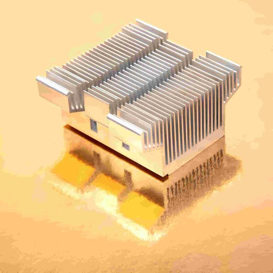
Aluminum heat sink (iStock)
Equipment builders also need assembly fixtures, calibration fixtures, optical mounts, sensor brackets, motor mounts, heat sinks, cold plates, and cooling blocks.
Brackets and mounts commonly involve pockets, slots, tapped holes, counterbores, and locating features. They may look less complicated than chamber components, but a production machine can use many different versions throughout an assembly.
Cold plates and cooling blocks involve more material removal. Their channels, connection ports, mounting holes, and mating faces are machined into one or more plates. Heat sinks may require repeated milling between fins, making cutter size and machining time important when the fin pattern becomes dense.
These parts can also combine processes. A cooling block might be milled and drilled, while a cylindrical thermal component may start on a lathe before secondary milling adds its mounting features.
What Makes Semiconductor CNC Machining More Demanding?
Semiconductor equipment machining can involve requirements beyond dimensional accuracy, including material compatibility, controlled surface condition, cleaning, and contamination control for parts exposed to vacuum, process gases, chemicals, or wafer-handling environments.
A semiconductor equipment drawing may combine general dimensions with a small number of critical features that control the machining sequence, workholding, tooling, or inspection method.
Aluminum has a relatively high coefficient of thermal expansion, so a temperature difference can affect measurements across a large part. As an example, a 500 mm aluminum dimension can change by roughly 0.06 mm with a 5°C temperature difference, depending on the alloy.
Dimensional Accuracy and Repeatability
For example, a drawing may specify a Ø12 H7 bore. The hole would normally be machined below the finished size first and then brought to tolerance by a suitable finishing operation, such as boring or reaming, depending on the material, depth, geometry, and required accuracy.
For a production batch, the bore can be checked at defined intervals during machining. If measurements begin moving toward one tolerance limit, the operator can correct the tool offset or replace a worn tool before continuing.
The drawing does not need the same treatment everywhere. A dowel bore may need a controlled fit, while a nearby bolt-clearance hole has room for assembly and can use a wider tolerance.
Surface Condition and Contamination Control
A machined manifold can look clean on the bench while chips remain inside a cross-hole. Blind tapped holes can also hold coolant and small chips at the bottom.
These areas need to be cleaned before the part is packed. Compressed air alone may move loose chips without removing machining residue. Where the drawing specifies a cleaning process, the shop follows that process after machining and deburring.
Handling after cleaning also counts. Placing a cleaned part back on a contaminated machine surface can compromise the cleaning result. Parts with specified cleanliness requirements need suitable handling and packing after the final clean.
Not every semiconductor equipment part has the same cleanliness requirement. Components exposed to vacuum, process gases, or wafer-handling environments may also require material and surface specifications that limit particle generation, outgassing, corrosion, or other contamination risks. These requirements should come from the equipment specification rather than being assumed for every CNC-machined part.
Material and Thermal Stability
Large aluminum parts with tight dimensional requirements may need to stabilize before final inspection, especially after long machining cycles that generate heat.
Machining heat and the temperature difference between the workpiece and inspection environment can affect measurements on large aluminum components. On a large component with a close tolerance, that temperature difference can be enough to affect the measurement.
Before critical dimensional inspection, allow the part and measuring equipment to stabilize thermally. Evaluate dimensions at the specified reference temperature, normally 20°C, or apply appropriate thermal-expansion compensation and account for measurement uncertainty. This is especially important for long dimensions and bore spacing on large aluminum parts.
Material condition matters before cutting as well. The drawing should state the alloy and temper, such as 6061-T6, rather than only calling for "aluminum." The temper affects the mechanical condition of the stock supplied to the machine shop.
Stress and Distortion Control
Consider a plate machined from a thick aluminum blank. Much of its central material is removed to form a cavity, but the finished part still has a flatness requirement across its mounting face.
Taking the cavity and mounting face directly to the final size in one clamping leaves no material for correction if the plate moves after release.
A safer machining route is to rough the cavity first and leave finishing stock. The plate is removed from the fixture, then set again for the final cuts. If the roughing operation has released enough stress to move the plate, the remaining stock gives the machinist something to correct.
The final flatness check is made after the part is unclamped. That measurement represents the part that will actually reach assembly, rather than the shape forced against the CNC fixture.

Precision CNC Machining Service
Professional manufacturing, fast turnaround, and quality assurance.
What Materials Are Used for Semiconductor CNC Machining?
Material selection should follow the part's functional requirements rather than the supplier's standard material list. Consider the loads, temperature, heat-transfer needs, chemical exposure, and electrical requirements that apply to the finished component.
These answers usually narrow the material selection to a practical range of candidates.
Aluminum Alloys
Aluminum is commonly used for equipment plates, bases, housings, stages, and larger machined blocks where low weight and good thermal conductivity are useful.
Aluminum 6061 works for many general equipment parts. If the design needs higher mechanical strength, aluminum 7075 gives you another option, although strength alone should not drive the selection.
For example, there is little benefit in specifying 7075 for a lightly loaded cover or mounting plate if 6061 already meets the design requirements.
Stainless Steel and Other Metal Alloys
Stainless steel can be selected where the component needs higher strength, corrosion resistance, or a material better suited to its operating environment. The required grade should be specified on the drawing rather than stated only as "stainless steel."
Copper belongs in a different category. Use it where electrical or heat transfer is part of the component's job. A copper contact and an aluminum mounting plate may sit in the same assembly, but they are selected for different reasons.
Engineering Plastics
Plastic makes sense where using metal would create another problem.
An insulating plate, for example, should not be made from aluminum simply because aluminum is easy to machine. FR4 can be considered for electrical-insulation components where its mechanical and thermal properties meet the application requirements.
POM can suit guides, spacers, and other low-friction components, while PMMA or PC may be selected for transparent covers or guards where the application permits.
How to Select a Material for Semiconductor Equipment Parts
Do not begin with a list of available materials. Begin with the part.
For a structural plate, check load, weight, and operating temperature. For a cooling component, add heat transfer to that list. For a gas or fluid part, check the actual chemical against the proposed material. For an electrical spacer or isolation plate, check insulation requirements before considering a metal.
Then specify the exact grade on the drawing. "Aluminum" leaves the supplier to determine the grade. "6061-T6" gives the purchasing and machining teams something definite to work with.
Finally, match that grade against the CNC supplier's available materials. JLCCNC currently supports aluminum, stainless steel, steel, copper, brass, and several engineering plastics for CNC machining.
What CNC Machining Processes Are Used for Semiconductor Parts?
The machining process follows the part geometry and drawing requirements. Milling handles prismatic parts and machined features on flat surfaces. Turning suits components based around a rotational axis. Parts with features in several orientations may require multi-axis machining or more than one operation.
CNC Milling and Multi-Axis Machining
CNC milling is used for semiconductor equipment parts made from plate, billet, or block material. Typical work includes machining faces, pockets, slots, bores, hole patterns, and threaded features.
The number and direction of these features affect the machine setup. Three-axis machining covers features accessible from fixed directions. Four-axis machining adds controlled part rotation. Five-axis machining provides access to more orientations without relying on as many separate setups.
The choice should come from the CAD geometry and drawing, not from selecting the machine with the highest axis count.
CNC Turning for Rotational Components
CNC turning is used where most of the part geometry shares a common axis. It produces outside and inside diameters, faces, shoulders, bores, and grooves.
If the same component also contains off-axis holes, flats, or other milled features, it may require additional machining. The process plan then combines turning and milling according to the finished geometry.
Production quantity can also affect the setup. Repeat production benefits from a defined process and workholding method that can be reproduced consistently across the order.
Secondary Machining and Surface Finishing
Secondary work covers features and treatments that remain after the main milling or turning operations. Depending on the drawing, this can include tapping, reaming, deburring, engraving, and specified surface treatment.
These operations should follow the part specification. A finish should not be added simply because it is commonly used on a particular material.
How Are Semiconductor CNC Machined Parts Inspected?
Inspection should follow the drawing. Inspection starts with the drawing requirements that determine acceptance, including critical dimensions, GD&T, surface requirements, material callouts, and notes that apply in the finished condition. This keeps inspection focused on requirements that determine whether the part can be accepted.
Dimensional and Geometric Inspection
Linear dimensions, hole diameters, depths, threads, and feature locations are checked against their drawing limits. Geometric controls are handled separately. Flatness, perpendicularity, parallelism, position, and runout are verified only where the drawing specifies them.
The measuring equipment depends on the feature. Calipers and micrometers can cover suitable dimensional checks. CMM inspection is particularly useful when feature location, datum relationships, or GD&T controls must be verified in a common coordinate system.
This also means there is no single tolerance that applies to every semiconductor CNC part. The drawing defines which dimensions need closer control and which can follow the stated general tolerance.
Surface, Cleanliness, Material, and Documentation Checks
Surface inspection covers the requirements stated for the finished part. This may include surface roughness, coating, visible damage, burrs, and specified cosmetic conditions.
Verify cleanliness against the requirements in the drawing, purchase specification, or agreed cleaning standard. Confirm completion of the required cleaning, handling, and packaging steps. Where particle, residue, or other contamination limits are specified, also verify compliance using the required test method and sampling plan; process completion alone does not demonstrate compliance with those limits.
Material verification starts with the material grade on the order and drawing. Where documentation is required, the supplied records should correspond to the material and finished parts in that order.
Application-Specific Functional Inspection
Some requirements can only be checked in relation to the part's intended function. These checks should be stated on the drawing, inspection specification, or purchase documents.
A part may require verification of a fit, assembly interface, sealing requirement, flow path, or another defined function. For a vacuum component with a leak-tightness requirement, specify the test method, acceptance leak rate and units, test conditions, and whether acceptance applies to the individual part or the assembled seal system. Dimensional and surface-roughness checks alone do not demonstrate leak-tightness.
This prevents unnecessary testing. A structural mounting part does not automatically need the same verification as a component with a specified sealing or flow function. The acceptance criteria come from the individual part specification.
What Design Considerations Matter for Semiconductor CNC Parts?
Design the part around its installed condition. Define the mounting references, mating surfaces, finished surfaces, and cleanliness requirements before releasing the drawing. This gives the CNC supplier clear manufacturing requirements instead of leaving functional decisions open during production.
Define Critical Interfaces and Tolerances
Identify the surfaces and features that establish the part's final position in the assembly. Use these as drawing datums.
For a component located by a mounting face and dowel holes, reference related bores, slots, and mounting positions from those features. Avoid dimensioning them from an unrelated outside edge.
Check the assembled dimensions as well. If the final position passes through a base, spacer, and mounted component, calculate the tolerance stack across those parts. This shows how much variation remains available for each component before assigning individual tolerances.
Keep general dimensions separate from these controlled interfaces. This prevents unnecessary close tolerances from spreading across the complete drawing.
Design for Tool Access and Part Stability
Review the CAD model from each machining direction before releasing it. Check whether cutters have direct access to pockets, holes, slots, and side features. Internal corner radii should match available cutter sizes. A small corner radius forces the use of a smaller end mill even when the rest of the pocket has enough space for a larger cutter.
Workholding also needs space on the part. Keep sufficient stock around the areas used for locating and clamping during machining. Leave enough usable area for locating and clamping, and check the setup sequence before distributing features across the part.
For thin sections, check the final assembly load as well as the machined shape. Fasteners applied close to a thin wall or floor introduce local loading after the part leaves inspection.
Consider Surface Treatment and Cleaning Requirements
Mark the finish directly on the surfaces it applies to. Also identify surfaces excluded from the treatment.
Where a coating changes the finished dimension, account for the coating condition when defining affected dimensions, fits, and masked surfaces. Threads, fitted bores, contact faces, and other interfaces need a clear requirement for whether they are finished, masked, or machined after treatment.
Review internal geometry for cleaning access. Avoid pockets that trap liquid and passages that cannot drain after washing. Provide open access to areas that require cleaning.
Place engraving, part numbers, and revision marks away from mating faces and other controlled surfaces. Specify their location on the drawing so identification remains consistent between production batches.
What Information Is Needed for a Semiconductor CNC Machining RFQ?
A useful RFQ gives the machine shop enough information to quote the part against the same production requirements that will govern manufacturing. Send the model, drawing, material, finish, inspection requirements, and quantity together. Missing requirements often lead to another quotation round before the order reaches engineering review.
Drawings, CAD Files, and Critical Requirements
Send both the 3D model and the controlled 2D drawing. The CAD file provides the geometry, while the drawing carries requirements that are not clear from the model alone.
- 3D CAD file: STEP is a practical file format for transferring the part geometry.
- 2D drawing: Add dimensions, tolerances, threads, GD&T, and drawing notes.
- Drawing revision: Use the same revision for the CAD file, drawing, and RFQ.
- Critical features: Identify the dimensions and interfaces that require specific control.
- Threads and inserts: State thread size, depth, quantity, and insert requirements.
- Units: Clearly state mm or inches.
- Part identification: Give each component a part number that matches the RFQ.
Do not send two files with conflicting dimensions. Resolve the difference before quotation, instead of leaving the supplier to choose which file controls production.
Material, Surface Finish, and Inspection Requirements
Write the exact material grade rather than a broad material family. The same applies to the finish.
- Material grade: For example, specify the required aluminum, stainless steel, copper, or plastic grade.
- Material condition: Add temper or other required condition when it forms part of the specification.
- Surface roughness: Mark the surfaces that carry a defined roughness requirement.
- Surface treatment: State the required treatment and its applicable surfaces.
- Masked areas: Identify threads, contact areas, fitted features, and other surfaces excluded from treatment.
- Inspection requirements: State the dimensions, GD&T characteristics, or other items requiring documented inspection.
- Material documents: List the certificates or material records required with the order.
- Part marking: Add the required part number, revision, or other identification and show its location.
- Cleaning and cleanliness: State the required cleaning process and any particle, residue, or other contamination limits, including the verification method.
- Functional acceptance: Include any leak, pressure, or flow tests, with acceptance limits and test conditions.
- Special capability confirmation: Ask the supplier to confirm any required controlled-environment processing, specialized finishing, testing, or packaging before placing the order.
Keep these requirements on the drawing or RFQ. A note such as "semiconductor quality" does not tell the machining team what finish, inspection, documentation, or handling the order requires.
Quantity, Application, and Delivery Requirements
Quantity affects material purchasing, setup planning, machining time, and the quotation. Give the required quantity for each part number rather than only the total project quantity.
- Quantity per part number: Separate prototype and production quantities.
- Quotation quantities: Request price breaks for the quantities you are actually considering.
- Application information: State the component's function when it helps engineers understand a specified interface or requirement.
- Required delivery date: Give the date and delivery window needed for the order.
- Partial delivery: State whether completed quantities can be shipped in batches.
- Packaging requirements: Include any specified protection, separation, bagging, or labelling.
- Destination: Provide the delivery country or location needed for the shipping quotation.
For a multi-part project, use an RFQ table with part number, revision, material, finish, quantity, and required date. The drawing and CAD filenames should use the same part numbers. This keeps the quotation tied to the correct files when several semiconductor equipment components are submitted together.
Semiconductor CNC Machining FAQs
Is Semiconductor CNC Machining the Same as Semiconductor Manufacturing?
Semiconductor CNC machining produces mechanical components for wafer-processing equipment. The work includes milling and turning parts from engineering drawings and CAD files. Semiconductor manufacturing processes the wafer itself through operations such as lithography, deposition, etching, and doping. These are separate manufacturing activities.
What Parts Are Commonly CNC Machined for Semiconductor Equipment?
Common machined parts include vacuum chamber components, wafer stages, flanges, manifold blocks, cooling plates, equipment mounts, fixtures, shafts, and adapters. Milling handles most plates, blocks, pockets, and hole patterns. Turning handles cylindrical parts and features such as bores, shoulders, diameters, and grooves.
What Materials Are Used for Semiconductor CNC Machined Parts?
Aluminum alloys are used for lightweight structural parts and components that transfer heat. Stainless steel is selected for higher strength and corrosion resistance. Copper provides high electrical and thermal conductivity. Engineering plastics provide electrical insulation and avoid metal-to-metal contact where the design requires it.
The drawing should specify the exact alloy, temper, or plastic grade required for production.
What Tolerances Are Common for Semiconductor CNC Machining?
There is no standard tolerance that covers all semiconductor equipment parts. Tolerance is assigned feature by feature.
A bearing bore, locating diameter, or controlled hole position can require a tighter limit than a clearance hole or outside profile. General dimensions can follow the drawing's stated general tolerance. The RFQ should include the complete drawing so the CNC supplier can price the actual tolerance requirements rather than only the nominal CAD geometry.
Does Semiconductor CNC Machining Require Cleanroom Manufacturing?
CNC machining and cleanroom manufacturing are separate requirements. A semiconductor equipment part can be machined in a CNC workshop and then pass through specified deburring, cleaning, handling, and packaging steps.
If cleanroom processing is required, the purchase specification should state the required environment or cleanliness standard. The same applies to special washing, particle limits, controlled packaging, and handling after cleaning.
Precision CNC Machining Service
Professional manufacturing, fast turnaround, and quality assurance.
Conclusion About Semiconductor CNC Machining
Semiconductor equipment contains a wide range of machined components, and not every part should be treated simply as a "high-precision" component. The required machining process depends on the part's functional interfaces, material, drawing requirements, and acceptance criteria.
Good production planning starts by identifying which requirements actually affect the part's function and acceptance. The drawing and RFQ should make those requirements clear enough for the manufacturer to choose a workable process route before production begins. Depending on the part, the manufacturing plan may need a different machining sequence or an additional setup before final inspection is completed against the critical datum or interface.
For prototype parts, this approach helps identify manufacturing issues before committing to a larger batch. For repeat orders, it gives the supplier a controlled specification to manufacture against each time.
Popular Articles
• Micro CNC Machining Explained: Process, Precision & How Small It Can Really Get
• CNC Machining in the Medical Industry
• CNC for Luxury Watchmaking: Achieving Sub-Micron Tolerances
• Micro CNC Machining: Techniques for Manufacturing Miniature Components
• CNC Machining vs Sheet Metal: Which is Better for Enclosures?
Keep Learning
CNC Motorcycle Parts: Types and How They Are Made
Key Takeaways CNC motorcycle parts are custom or production components machined from CAD models to achieve specified mounting interfaces, dimensions, and surface features. CNC is well suited to brackets, covers, spacers, bushings, and low-volume replacements, but parts affecting braking, steering, suspension, wheel retention, or rider safety require engineering validation beyond machinability. CNC milling suits brackets, covers, and parts with complex profiles, while CNC turning is used for shafts, bu......
Micro CNC Machining Explained: Process, Precision & How Small It Can Really Get
Explaining Micro CNC Machining Any machinist can machine a block of aluminum into a bracket. But what happens when your part is the size of a grain of rice, and still needs tolerances tighter than a human hair? That's when “standard CNC” suddenly feels clumsy, and every micron starts to matter. This is the world of micro CNC machining. It's not about big, impressive cuts, it's about making the kind of components you'll never notice… until they fail. Like the gears in a luxury watch, the nozzles in med......
Custom Bicycle Parts: CNC Machining Guide
Key Takeaways CNC machining is often a practical choice for custom bicycle parts when production quantities are low, the geometry is complex, or critical interfaces require tighter dimensional control than near-net-shape forming can provide. The parts that benefit most are the ones where fit accuracy genuinely matters, such as bearing seats, bottom bracket interfaces, derailleur mounting features, and suspension pivots, where dimensional variation can affect assembly and performance. For CNC-machined ......
Online CNC Machining Services for Startups: Benefits & Uses
Key Takeaways Online CNC machining lets startups upload CAD files, get quotes, order custom parts, and manage production through a digital workflow. Prototyping: Startups can order single or small quantities to test fit, function, materials, and designs before scaling production. Production flexibility: The same CNC service can support prototypes, small batches, and higher quantities as product demand develops. Cost factors: Material, part size, geometry, tolerances, quantity, machining requirements, ......
CNC Machining for the Automotive Industry
Key Takeaways Automotive CNC machining is used both to produce certain low-volume components directly and to finish cast or forged parts at critical interfaces, including engine blocks, transmission housings, suspension uprights, brake components, and EV motor housings. CNC machining isn't how most automotive parts get manufactured in volume; casting, forging, and stamping handle the majority of mass production. What CNC does well is prototyping, low-volume production, precision finishing of cast or f......
CNC Machining for the Optics Industry: Optical Components & Housings
Key Takeaways CNC machining for optical systems primarily produces optomechanical components that hold, locate, align, and protect optical elements, including housings, lens barrels, mounts, spacers, retaining rings, and alignment fixtures. Conventional CNC machining is primarily used for the mechanical components around optical elements, while lenses and mirrors are generally produced through specialized grinding, polishing, coating, or ultra-precision machining processes. CNC machining provides the ......