CNC Machining for the Optics Industry: Optical Components & Housings
22 min
- What Optical Components Can Be CNC Machined?
- What Precision Requirements Matter for Optical Components?
- Materials for CNC Machined Optical Components
- Design Considerations for CNC Machined Optical Components
- CNC Machining and Inspection Methods for Optical Components
- Surface Finishing for Optical Components
- Applications of CNC Machined Optical Components
- CNC Machining for Optical Components FAQs
- Conclusion About CNC Optical Components
Key Takeaways
- CNC machining for optical systems primarily produces optomechanical components that hold, locate, align, and protect optical elements, including housings, lens barrels, mounts, spacers, retaining rings, and alignment fixtures.
- Conventional CNC machining is primarily used for the mechanical components around optical elements, while lenses and mirrors are generally produced through specialized grinding, polishing, coating, or ultra-precision machining processes.
- CNC machining provides the mechanical structure that locates, supports, and retains optical elements; the geometry of these components can directly affect alignment, repeatability, and stability in the finished assembly.
- Feature-to-feature geometric relationships, such as runout, perpendicularity, position, and coaxial relationships, can matter more than a tight general dimensional tolerance.
- Material selection affects machinability, thermal dimensional stability, stiffness, and compatibility with the optical assembly and surface finish.
- Surface finish and coating choices can also affect stray-light control, interface dimensions, and the condition of surfaces surrounding the optical elements.
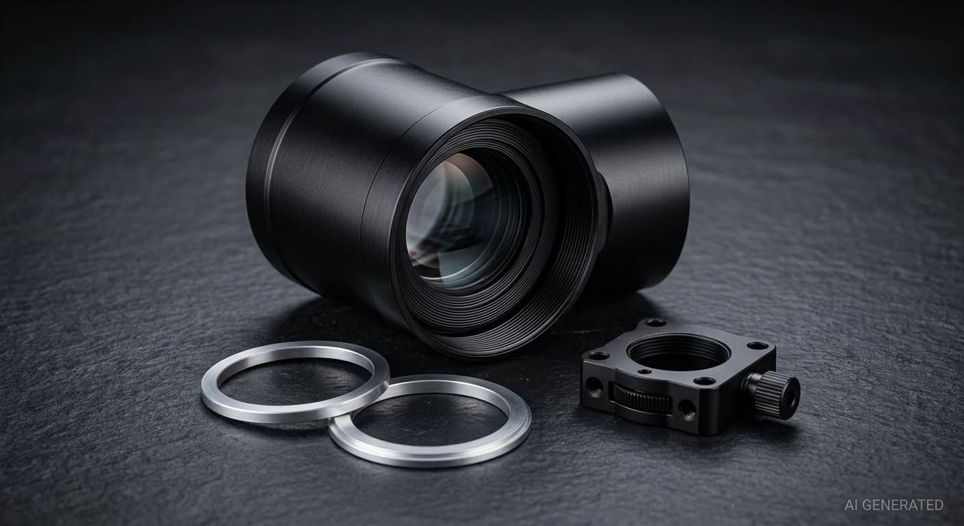
Precision CNC-machined optical assembly
In optomechanical machining, a part can meet its dimensional tolerances and still misalign the optical assembly. For example, a lens bore may be within its diameter limits while showing excessive runout relative to the mounting datum, shifting the optic axis or introducing tilt. A housing bore can meet its size tolerance while still being misaligned relative to the functional datum, introducing decenter or tilt error that may degrade optical performance depending on the system's alignment budget. Machining burrs or damaged thread edges on a retaining ring can release particles during installation and create a contamination risk for nearby optical surfaces.
This guide covers the full picture of CNC machining for optical components: what gets machined, what the real precision requirements are, which materials work and why, and how inspection connects back to what matters optically.
What Optical Components Can Be CNC Machined?
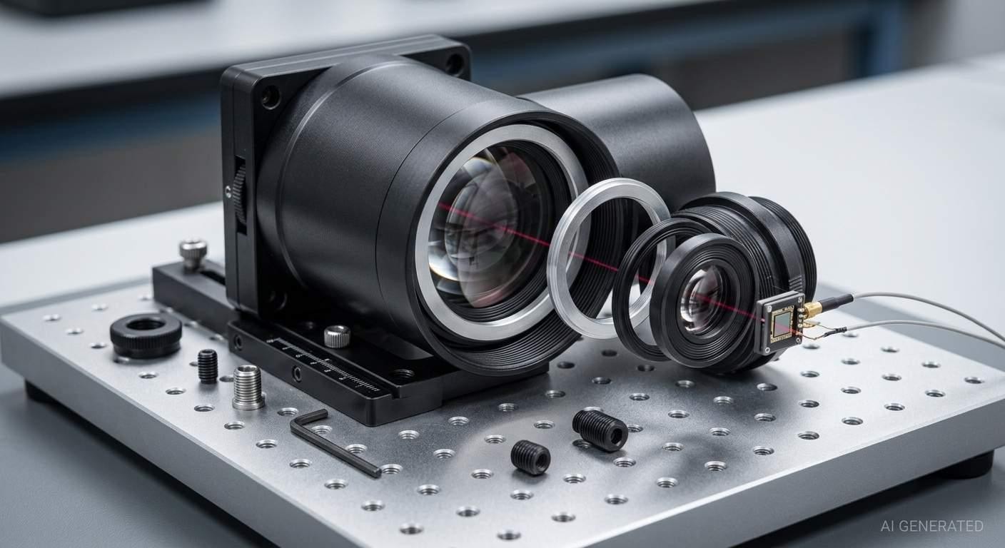
Precision optical assembly being aligned on a compact optical breadboard
Conventional CNC machining is primarily used for the mechanical components around optical elements rather than finished glass or crystal optics. Lenses, prisms, and figured mirrors are typically produced through grinding, polishing, coating, or specialized ultra-precision processes, although certain infrared optical materials can be machined directly by diamond turning.
Optical Housings and Enclosures
The housing is usually the primary structural component of an optical assembly. It provides the mechanical references that locate the optical axis and establishes the mounting interfaces used to position internal components, while protecting them from contamination and mechanical disturbance.
Machining a housing well requires controlling the bore-to-datum relationship, seating surfaces, and wall geometry while limiting distortion during machining and operation. The tolerances on a camera housing for a machine vision system might be moderate by precision machining standards. A housing for a space-based instrument is a different matter entirely.
The required tolerance, material stability, and inspection scope depend on the alignment budget, operating environment, and consequences of assembly error. A general machine-vision housing may use relatively moderate tolerances, while a space-based optical instrument can require tighter geometric control, thermal analysis, and documented inspection of critical interfaces.
Lens Barrels and Lens Holders
A lens barrel is essentially a tube with carefully controlled internal bore geometry, threads for retaining rings, and reference surfaces that locate it within an outer housing. The bore and seating features need controlled size, form, and geometric relationships appropriate to the optic, retention method, and allowable decenter or tilt. Retaining-ring threads need the specified pitch, form, fit, and surface condition to provide predictable axial positioning and secure retention without damaging or contaminating nearby optical surfaces. Additionally, specialized internal thread profiles (such as light baffle threads) are often machined into the barrel not for fastening, but specifically to trap stray light and improve image contrast.
Lens holders designed for adjustable mounts have additional complexity, flexure features, adjustment screw interfaces, or spring preload geometries machined into the same part that holds the optical element. These require planning the machining sequence carefully because features that are easy to machine on a simple cylinder become difficult once other features are present.
Optical Mounts, Spacers, and Retaining Rings
Spacers set the axial distance between lens elements. Getting that distance right across a multi-element assembly is a tolerance stackup problem. Spacer tolerances should be allocated from the total axial spacing budget rather than tightened uniformly by default. A tolerance-stack analysis determines how much variation each spacer can contribute while keeping the assembled optical spacing within the required range. For precision assemblies, spacer thickness should be allocated from the axial stack-up. Where the allowable assembly variation is small, spacers may be matched or selectively assembled rather than assigned an unnecessarily tight blanket tolerance.
Retaining rings thread into lens barrels to hold elements in place. The concern here is thread form quality and chip control during machining. A retaining ring that generates chips during installation is a contamination risk that's hard to recover from after the assembly is together.
Alignment Fixtures and Mounting Components
These are the kinematic mounts, V-groove fixtures, and precision dovetail carriers that position optical elements within a system. They tend to have complex geometric relationships between features. The V-groove that locates a cylindrical optic needs to be at a precise angle and position relative to the bolt pattern that attaches the fixture to an optical table. Getting this right requires careful datum planning and a machining sequence that minimizes setup-to-setup error. Multi-axis machining can reduce refixturing for suitable geometries.
For a deeper explanation of concentricity, perpendicularity, true position, and datum-based inspection, see our guide to GD&T in CNC machining.
What Precision Requirements Matter for Optical Components?
Optical components do not need the tightest possible tolerance on every dimension. What matters is whether each tolerance protects a functional relationship in the optical system. A lens barrel may need ordinary dimensional control on nonfunctional exterior surfaces while requiring much tighter control of the bore, seating shoulder, thread, and mounting datum relationships.
Alignment and Geometric Relationships
Take a lens barrel. The lens bore and the outer locating diameter need a controlled axis relationship. Depending on the functional requirement and drawing standard, that relationship may be specified through position or runout rather than a generic concentricity callout. If the bore axis is displaced from the intended reference axis, the optic can be decentered; angular error between the bore axis and seating surfaces can introduce tilt. Either error can affect optical performance depending on the system's sensitivity. The required geometric tolerance depends on the optical system's alignment budget. That's not a remarkable dimensional tolerance for a capable turning operation, but it has to be consistently achieved across every part.
Perpendicularity matters for the reference surfaces that seat against other components. A shoulder that's not perpendicular to the bore axis tilts whatever element rests against it. In a multi-element assembly, these errors accumulate. The end-to-end alignment error at the image plane can be significantly worse than any individual feature tolerance suggests if the errors add rather than cancel.
True position on bolt patterns and mounting holes affects how the component sits relative to the rest of the system. True position of mounting holes affects how accurately the optical assembly locates relative to the machine structure. Position errors can introduce assembly offset or alignment error, which may require adjustment or shimming during system integration.
Threads, Mating Interfaces, and Assembly Repeatability
Threads in optical assemblies serve positioning functions as well as retention. In an adjustment mechanism, thread lead—not pitch alone—determines axial travel per revolution. For a single-start thread, lead equals pitch, while a multi-start thread has a lead equal to pitch multiplied by the number of starts. Lead accuracy and backlash therefore affect repeatable adjustment. Thread quality affects repeatability. Thread lead, pitch accuracy, flank condition, clearance, and burr control can all affect axial seating repeatability. In adjustment mechanisms, lead accuracy directly affects displacement per revolution, while in retaining threads the primary concern is controlled seating and preload without damaging the optic.
Mating interfaces, the shoulders, bores, and datum surfaces that locate one part relative to another, need to fit consistently. A lens barrel that drops into a housing with a specific clearance fit should seat identically every time. If the fit varies between parts, the assembly alignment varies, and the system needs individual adjustment rather than being interchangeable.
If you're specifying clearance or interference fits between optical components, see our guide to limits and fits in CNC machining.
Burr Control, Cleanliness, and Part Condition
Burrs on internal edges in optical assemblies are a real contamination risk. A burr inside a lens barrel can loosen during handling or service and release particles into an enclosed optical assembly, where removal may require partial or complete disassembly. Burr risk should be addressed through edge design, toolpath direction, cutting parameters, and a defined deburring step rather than relying on visual inspection alone. Internal bores, thread starts, cross-holes, and intersecting pockets deserve particular attention because burrs in these areas are easy to miss and difficult to remove after assembly.
Cleanliness requirements for precision optical assemblies often exceed what a standard machine shop considers clean. Parts for contamination-sensitive optical assemblies may require a defined post-machining cleaning process, which can include ultrasonic cleaning where the materials and assembly are compatible, followed by inspection for particles, residue, and surface contamination.
Have an optical housing, lens barrel, mount, or other precision mechanical component to manufacture? Upload your CAD file and drawing for a project-specific quotation and manufacturing review.

Precision CNC Machining Service
Professional manufacturing, fast turnaround, and quality assurance.
Materials for CNC Machined Optical Components
Material selection for an optomechanical component should follow the system's thermal, structural, mass, corrosion, and finishing requirements. Available material grades and manufacturing routes should be confirmed against the supplier's current material list and the project drawing.
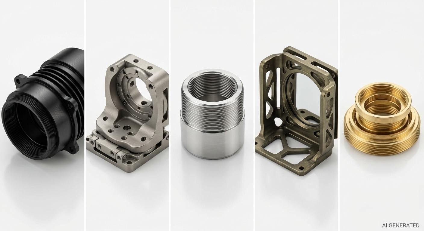
CNC-machined optical components manufactured
Material selection for optomechanical parts typically balances coefficient of thermal expansion, stiffness, mass, machinability, corrosion resistance, and compatibility with the required surface treatment. In many optical assemblies, the material matters because it determines how reliably the mechanical interfaces maintain their position as temperature and environmental conditions change.
6061-T6 is commonly selected for optical housings, mounts, and brackets because it combines low density, good machinability, adequate stiffness, and good anodizing compatibility. 7075-T6 may be selected when higher strength is needed, although the alloy and finish requirements should be reviewed together before production.
Good machinability, low density, reasonable stiffness, and excellent response to anodizing make aluminum the widely used material for most visible-wavelength systems operating in benign environments. The CTE of aluminum (about 23 µm/m·°C) is acceptable for many applications but becomes a concern in high-precision systems or those with wide operating temperature ranges.
Titanium may be selected in aerospace optomechanical applications when lower thermal expansion, high specific strength, or compatibility with certain composite structures is important. Titanium's CTE (8-9 µm/m·°C) is close to carbon fiber composites, which reduces differential thermal expansion at structural interfaces. It's harder to machine than aluminum and considerably more expensive, so it only appears where the CTE requirement justifies it.
Invar and Super-Invar are nickel-iron alloys with extremely low CTE, around 1-2 µm/m·°C. Used in applications where dimensional stability across temperature is critical and weight is secondary. Machining Invar requires attention to work hardening and tool wear, and the material is expensive and heavy. Furthermore, Invar often requires extensive stress-relief annealing cycles between roughing and finishing operations to prevent long-term dimensional drift in the final optical assembly.
Stainless steel appears where corrosion resistance matters or where higher stiffness per cross-section is needed. Harder to machine than aluminum but reasonable for many optical component geometries.
Brass is used for small turned components such as spacers, retaining rings, and threaded adapters where machinability, dimensional stability, and wear behavior are appropriate for the application.
Design Considerations for CNC Machined Optical Components
Critical Features, Datums, and Tolerance Allocation
One of the most important design decisions for an optical component is how the datum structure relates to the actual assembly interfaces. Which surfaces establish the reference frame from which everything else is measured and assembled? Getting this wrong means the part can be individually conforming but systematically misaligned when assembled.
The datum structure should reflect assembly priority. If the outer diameter is the functional locating interface, the drawing should establish the datum structure from that interface and control the internal bore's location or axis relationship accordingly. That matches how the part actually gets constrained in assembly. If the drawing controls the wrong feature relationship, a part can pass inspection and still be misaligned in assembly. For example, if the outer locating diameter is the functional mounting interface, the drawing should establish the datum structure from that interface and control the lens bore axis relative to it.
Tolerance allocation across a multi-component optical assembly requires stackup analysis before drawing dimensions get assigned. It's common to work backward from a system-level alignment budget, allocate that budget across components, then check whether the individual tolerances are achievable given the geometry and processes planned.
Thin Walls, Deep Bores, and Tool Access
Optical housings often use thin walls to reduce mass and envelope size while preserving the required bore. Thin sections are prone to cutting-force deflection and springback, so the roughing and finishing sequence, as well as the point at which thin walls are opened, can affect final roundness and size. Thin walls deflect under machining forces and can spring back after cutting, producing out-of-round bores and off-tolerance surfaces. The sequence of roughing and finishing passes, and the order in which thin sections are created, affects how much deflection occurs during critical operations.
For deep bores, tool stickout-to-diameter ratio becomes a major constraint. Long boring bars and end mills are more prone to deflection and chatter, which can affect bore size, roundness, cylindricity, and surface finish. Tool diameter, holder rigidity, roughing allowance, finishing strategy, and chip evacuation should therefore be planned together.
Workholding and Machining Sequence
Thin-walled cylindrical parts distort when clamped in a standard three-jaw chuck. On thin-walled cylindrical parts, excessive or uneven three-jaw chucking force can distort the workpiece and produce out-of-round bores that change after unclamping. For bores with tight roundness or alignment requirements, soft jaws matched to the locating diameter, collet chucks, or expanding mandrels may be selected to reduce clamping distortion. The appropriate method depends on which surfaces are functional datums and whether the critical bore is machined before or after the locating diameter.
For more on how fixturing and clamping affect dimensional accuracy and part deformation, see our CNC workholding guide.
Machining sequence has real consequences for optical components because each setup introduces its own reference and tolerance accumulation. Each additional setup introduces another source of location error because the critical relationship has to be re-established. When geometry allows, critical coaxial, perpendicular, or positional features are often completed from a common setup. When multiple setups are unavoidable, functional datums and locating features should be used to control the transfer between operations.
Thermal Expansion and Dimensional Stability
Parts measured at 20°C in a metrology lab are at a different temperature than they were during machining. Aluminum expands at 23 µm/m·°C. A 200 mm diameter aluminum bore changes in size by roughly 0.0046 mm for each 1°C change in temperature, based on an approximate CTE of 23 µm/m·°C. For tight-tolerance parts, both machining temperature and inspection temperature therefore matter.
In service, optical assemblies can experience temperature changes that shift component dimensions. For systems that need to maintain alignment across temperature ranges, the differential CTE between components needs to be analyzed. Two aluminum parts may have similar thermal expansion, but their dimensions and fit still change with temperature. When dissimilar materials are combined, differential CTE can change clearance, interference, or preload more significantly over the operating temperature range. For example, an aluminum housing supporting a glass optic cannot be evaluated only at room temperature; the mounting strategy needs to account for the different thermal expansion of the mechanical and optical elements.
CNC Machining and Inspection Methods for Optical Components
Milling, Turning, and Multi-Axis Machining
Turned components, lens barrels, spacers, retaining rings, and round housings are machined on a lathe or turning center. Turning can machine the OD and internal bore from a common spindle axis in the same setup, reducing setup-transfer error. The resulting coaxiality or runout still depends on workholding, spindle condition, tooling, thermal stability, and process control.
Milled features on turned parts, flats for wrench engagement on retaining rings, cross-drilled holes, and keyways require either live tooling on the turning center or a second setup on a mill. The precision of milled-to-turned feature relationships depends on how the handoff between operations is managed.
Multi-axis machining combines turning and milling in single setups, or allows complex prismatic housings to be completed without multiple refixturings. For optical housings with features distributed across multiple faces, 4- and 5-axis machining can reduce setup changes and help preserve geometric relationships between critical features when the process is properly planned.
Inspection of Critical Features and Alignment Relationships
CMM inspection is commonly used to verify dimensional and geometric requirements such as bore location, perpendicularity, runout, and position relative to the specified datum reference frame. A CMM probes actual surface points and calculates geometric deviations from the nominal, referenced to the datum structure established in the inspection program. The datum hierarchy in the inspection program should match the datum hierarchy on the drawing and in assembly. Otherwise, you're measuring something different from what matters.
Dedicated roundness and cylindricity measurement systems rotate the part or probe around the feature to characterize form error more directly than a conventional CMM. They are useful when bore form is itself a critical characteristic and the measurement uncertainty of a CMM is not sufficient for the required tolerance.
Surface finish measurement after machining and before finishing confirms that the machined surface meets requirements for coating adhesion or as-machined appearance. For black-anodized optomechanical parts, the machined substrate texture can affect coating appearance and reflectance; surfaces with significantly different roughness may not produce the same optical appearance after anodizing.
Surface Finishing for Optical Components
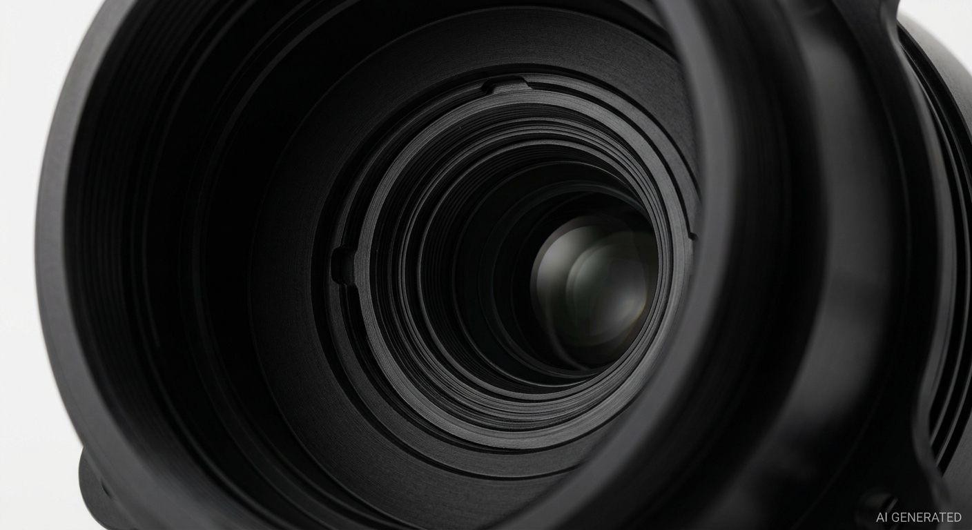
Black anodized aluminum optical housing
Black Anodizing and Surface Appearance
Black anodizing is commonly used on aluminum optomechanical components where stray-light control is important. A low-reflectance black surface helps reduce internal reflections and stray light that could otherwise reach a detector or sensitive optical path. The quality of the black anodizing, how uniform the color is, and how matte the surface is, depends on the substrate surface finish and the anodizing process parameters.
Machined surfaces that will be black anodized need to have consistent surface texture. Areas with different roughness anodize to different apparent darkness, which produces visible mottling and non-uniform light absorption. Controlling machining parameters to produce consistent surface finish across an entire housing interior matters for the optical performance of the finished assembly, not just for appearance.
A controlled blasting or surface-preparation step may be used before anodizing to create a more uniform surface texture, but the required pretreatment depends on the appearance, reflectance, coating specification, and critical dimensions of the part.
Coating Thickness and Critical Interfaces
Anodizing changes part dimensions because the oxide layer forms partly within the aluminum substrate and partly outward from the original surface. The dimensional effect depends on the anodizing type, coating thickness, alloy, and pretreatment, so critical bores, threads, fits, and locating surfaces should be dimensioned with the final coated condition in mind. Critical dimensions should be controlled against the required post-anodize condition. Depending on the feature and coating specification, the process may require machining allowance, masking, or post-anodize sizing rather than simply applying the nominal pre-coating dimension.
This is a source of assembly problems that comes up regularly in optical component manufacturing. For example, a precision housing bore can become undersized after anodizing if the machining allowance does not account for the coating process, reducing the intended clearance with the mating lens barrel. For critical interfaces, the drawing and process plan should define whether the dimension applies before or after anodizing and specify the required coating condition. Machining allowance, masking, or post-anodize finishing can then be used to achieve the final functional dimension.
For really critical dimensions, datum surfaces, precise clearance fits, masking during anodizing to keep those surfaces bare aluminum is sometimes specified. Uncoated aluminum then gets a different treatment, either chromate conversion coating for corrosion resistance or is accepted as bare with appropriate design allowances.
Applications of CNC Machined Optical Components
Imaging, Machine Vision, and Sensor Systems
Industrial machine vision cameras, line scan imaging systems, and scientific sensors all rely on machined optical housings and lens mounts for their mechanical structure. These systems typically need to maintain calibrated alignment between the lens and sensor across operational temperature ranges and vibration environments. The housing that positions the lens relative to the image sensor is the part that determines how stable that calibration is.
Thermal changes in the housing can shift the relative position of the lens and sensor, which may appear as image-position or measurement drift in a calibrated vision system. This drives housing designs that use materials with appropriate CTE for the operating environment and feature designs that minimize sensitivity to temperature changes.
Lasers, Photonics, and Optical Instruments
Laser systems need housings that maintain beam path alignment across operating conditions. A beam steering mirror mount that shifts thermally will move the output beam. Fiber coupling assemblies need the end of the optical fiber positioned relative to a lens with micron-level accuracy, achievable with precision-machined V-grooves and alignment features, but only if those features are in the right relationship to each other.
Scientific instruments, spectrometers, interferometers, and telescopes often represent the more demanding end of what CNC machining supports in the optics field. These instruments need housings that maintain alignment through temperature cycling, mechanical loads, and sometimes vacuum environments. Material selection, tolerance allocation, and surface treatment all have to be considered together rather than independently.
CNC Machining for Optical Components FAQs
Q: What is CNC machining for optical components?
CNC machining for optical components produces the mechanical parts that house, align, and retain optical elements in optical and photonic systems, lens barrels, housings, mounts, spacers, and retaining rings. The lenses, mirrors, and other optical elements themselves are made by optical fabricators through grinding and polishing. CNC machining provides the mechanical infrastructure those elements sit in, and the precision of that mechanical structure determines how well the optical system performs.
Q: What materials are commonly used for CNC optical components?
Aluminum is widely used for lightweight housings and mounts. Titanium, Invar, and stainless steel may be selected when thermal stability, strength, stiffness, or corrosion resistance is more important. Brass is commonly used for small turned components such as spacers, retainers, and threaded adapters. Material availability depends on the manufacturer and project requirements.
Q: How precise does CNC machining need to be for optical components?
There is no single CNC tolerance that defines an “optical” component. The required accuracy depends on the system alignment budget and the function of each interface. A drawing may control bore size together with runout, position, perpendicularity, or other geometric requirements when the relationship between features is functionally important.
Q: What CNC processes are used for optical components?
Turning for cylindrical components, lens barrels, housings, spacers, retaining rings. Milling for housings with prismatic features, mounting interfaces, and pocket geometries. Multi-axis machining for complex housings where feature relationships require machining multiple surfaces without refixturing. Combination turning-milling centers for components that need both turning and milled features in precise relationship.
Q: How are CNC machined optical components inspected?
CMM inspection can verify bore size, feature location, perpendicularity, position, runout, and other dimensional or geometric requirements relative to the drawing's datum reference frame. Legacy drawings may still use concentricity or coaxiality-related callouts, depending on the applicable standard.
Dedicated roundness measuring instruments for precision bore roundness and cylindricity where CMM measurement uncertainty is insufficient. Surface profilometry for machined surface finish before and after finishing. Visual and tactile inspection for burrs, edge condition, and surface contamination before assembly. First-article inspection may be required for aerospace, regulated, or customer-specific programs, while other optical components may use a defined dimensional inspection report based on the drawing and inspection plan.
Precision CNC Machining Service
Professional manufacturing, fast turnaround, and quality assurance.
Conclusion About CNC Optical Components
CNC machining for optical systems is fundamentally an optomechanical manufacturing challenge: the machined structure must maintain the required geometry, interfaces, and dimensional stability throughout assembly and operation. The requirements that differentiate optical component machining from general precision machining are the emphasis on geometric relationships between features, the sensitivity of the finished system to mechanical alignment errors, and the functional consequences of contamination and surface condition.
Understanding what actually drives optical system performance, which features matter, how tolerances stack up in assembly, why burrs and cleanliness are functional concerns rather than cosmetic ones, is what allows a machining operation to produce parts that work as designed rather than parts that pass dimensional inspection but fail in assembly.
For optical-component projects, JLCCNC can review the submitted CAD files and drawing requirements to confirm material, tolerance, finishing, and manufacturing requirements before production.
When the part includes critical bores, datum relationships, tight fits, or special inspection requirements, providing the drawing and relevant specifications helps define the appropriate manufacturing and inspection approach.
Upload Your Files for Engineering Review and Quote at JLCCNC
Popular Articles
• CNC Machining in the Medical Industry
• CNC for Luxury Watchmaking: Achieving Sub-Micron Tolerances
• Micro CNC Machining: Techniques for Manufacturing Miniature Components
• CNC Machining vs Sheet Metal: Which is Better for Enclosures?
• Micro CNC Machining Explained: Process, Precision & How Small It Can Really Get
Keep Learning
Custom Bicycle Parts: CNC Machining Guide
Key Takeaways CNC machining is often a practical choice for custom bicycle parts when production quantities are low, the geometry is complex, or critical interfaces require tighter dimensional control than near-net-shape forming can provide. The parts that benefit most are the ones where fit accuracy genuinely matters, such as bearing seats, bottom bracket interfaces, derailleur mounting features, and suspension pivots, where dimensional variation can affect assembly and performance. For CNC-machined ......
Online CNC Machining Services for Startups: Benefits & Uses
Key Takeaways Online CNC machining lets startups upload CAD files, get quotes, order custom parts, and manage production through a digital workflow. Prototyping: Startups can order single or small quantities to test fit, function, materials, and designs before scaling production. Production flexibility: The same CNC service can support prototypes, small batches, and higher quantities as product demand develops. Cost factors: Material, part size, geometry, tolerances, quantity, machining requirements, ......
CNC Machining for the Automotive Industry
Key Takeaways Automotive CNC machining is used both to produce certain low-volume components directly and to finish cast or forged parts at critical interfaces, including engine blocks, transmission housings, suspension uprights, brake components, and EV motor housings. CNC machining isn't how most automotive parts get manufactured in volume; casting, forging, and stamping handle the majority of mass production. What CNC does well is prototyping, low-volume production, precision finishing of cast or f......
CNC Machining for the Optics Industry: Optical Components & Housings
Key Takeaways CNC machining for optical systems primarily produces optomechanical components that hold, locate, align, and protect optical elements, including housings, lens barrels, mounts, spacers, retaining rings, and alignment fixtures. Conventional CNC machining is primarily used for the mechanical components around optical elements, while lenses and mirrors are generally produced through specialized grinding, polishing, coating, or ultra-precision machining processes. CNC machining provides the ......
Semiconductor CNC Machining: Precision Parts for Semiconductor Equipment
Key Takeaways CNC machining produces semiconductor equipment parts such as vacuum plates, manifolds, chambers, stages, brackets, and equipment housings. The function of a feature should set its machining requirements. A sealing surface needs suitable flatness and surface condition, while locating holes depend more on diameter and position. Large pockets can make an aluminum plate move after material removal. Roughing and finishing operations may therefore need separate setups. Thin walls can deflect u......
CNC Machining for Electronic Hardware: Design, Tolerances, and Manufacturing Considerations
(AI-generated) CNC milling of an aluminum electronics enclosure CNC machining plays a supporting but critical role in electronics manufacturing. While PCB fabrication creates traces, vias, and plated circuit features, CNC machining is used to produce the structural and mechanical parts that help the final device function reliably. What Is CNC Machining for Electronics CNC machining for electronics is the process of manufacturing high-precision mechanical parts used to support, protect, align, cool, or......