Limits and Fits: A Complete Guide to Hole and Shaft Fits
23 min
- What Are Limits and Fits?
- How Limits and Fits Work
- Types of Engineering Fits
- Clearance, Transition, and Interference Fit Examples
- Limits and Fits in CNC Machining
- How to Choose the Right Engineering Fit
- How to Specify Limits and Fits on Engineering Drawings
- Conclusion About Limits and Fits
- FAQs About Limits and Fits
Key Takeaways
- Limits and fits define the allowable dimensional variation for mating hole and shaft features and the resulting assembly relationship between them.
- ISO 286 is the international standard for engineering fits, using letter codes for fundamental deviation and number grades (IT grades) for tolerance band width.
- The three types of engineering fits are clearance fit (always a gap), interference fit (always an overlap), and transition fit (either gap or overlap depending on actual dimensions).
- Hole and shaft fits are most commonly specified in the hole-basis system, the hole is fixed at H (zero lower deviation from basic size) and the shaft varies.
- Tighter fit requirements may require finishing processes such as precision boring, reaming, grinding, or honing, depending on the feature geometry, material, nominal size, and required tolerance.
- The most common fit designation in general engineering is H7/g6, a close-running clearance fit used for precision sliding and rotating components.
Every time a shaft goes into a hole, in a bearing housing, a pump body, a gearbox casing, a fixture plate, someone made a decision about how much bigger or smaller one should be relative to the other. That decision is called an engineering fit, and the dimensional limits that define it are what this guide covers.
Get engineering fits right and parts assemble correctly, move freely or grip permanently as designed, and work reliably for the life of the machine. Get them wrong and you're either pressing parts that should slide together or wobbling with parts that should be rigid.
At JLCCNC, machining tolerances and fits are reviewed before production on every precision order, because the tolerance callout on a drawing is only useful if the manufacturing process can actually hold it.

Precision CNC Machining Service
Professional manufacturing, fast turnaround, and quality assurance.
Fit Selection Quick Guide
| Fit Category | Common ISO Fit | Assembly Characteristics | Typical Applications |
|---|---|---|---|
| Clearance (Free) | H9/d9 | Loose gap, turns freely, tolerates heat/dirt | Standard pulleys, non-critical rotating shafts, loose hinges |
| Clearance (Close) | H7/g6 | Very small gap, smooth precise rotation | Precision spindles, sliding gears, accurate guide pins |
| Transition | H7/k6 | Zero to slight interference, easy to disassemble | Locating dowels, gear hubs on keyed shafts, fixture locators |
| Interference (Press) | H7/p6 | Moderate interference, requires arbor press or hydraulic press to assemble | Bearing end caps, coupling hubs, semi-permanent press fits requiring press equipment |
| Interference (Shrink) | H7/s6 | Heavy interference, requires high force/heat | Permanent bearing housings, coupling hubs, pressed sleeves |
All fits shown use the hole-basis system (ISO 286), where the hole tolerance is held constant at H and the shaft tolerance is varied to achieve the desired fit type.
What Are Limits and Fits?
Limits and fits is the engineering system for specifying and communicating the allowable size variation for mating features, primarily holes and shafts, and the dimensional relationship that results when those features are assembled.
Three concepts form the foundation:
Nominal size is the intended design dimension, 25mm, 50mm, 100mm. This is the number from which everything else is calculated.
Limits are the upper and lower acceptable bounds, the maximum and minimum dimensions a feature can have and still conform to specification. The difference between upper and lower limit is the tolerance.
Fit is what results when a hole and shaft within their respective limits are assembled. Depending on where each dimension falls within its tolerance range, the assembly might have a gap, an overlap, or an uncertain result.
Limits vs. Tolerance vs. Fit
These three terms are often used interchangeably but they're distinct:
| Term | What it describes | Example |
|---|---|---|
| Limits | The actual dimensional boundaries (max and min) for one feature | 25.000mm to 25.021mm |
| Tolerance | The total permitted variation in one feature (upper limit minus lower limit) | 0.021mm |
| Fit | The assembly relationship between two mating features | Clearance of 0.007mm to 0.041mm |
A tolerance describes one part. A fit describes two parts assembled together. Limits are what you write on the drawing to achieve the fit you designed.
Why Limits and Fits Matter in Engineering
No manufacturing process produces exactly the nominal dimension every time. A CNC boring operation programmed to produce a 30mm bore produces something between 29.985mm and 30.021mm on different parts from the same setup, depending on tool wear, thermal state, and material variation. Limits and fits acknowledge this reality and specify the acceptable variation range that still produces functional assemblies.
Without a limits and fits system, every mating pair would require selective fitting, measuring each part individually and pairing them manually to achieve the required assembly relationship. With proper engineering fits specified from a standardized system like ISO 286, any shaft within its limits assembles correctly with any hole within its limits, which is what enables interchangeable manufacture at scale.
How Limits and Fits Work
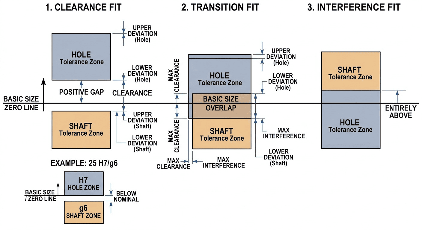
ISO 286 hole and shaft tolerance zones
Nominal Size and Tolerance Zone
The tolerance zone is the region between the upper and lower limits, a band of acceptable dimensions centered on or offset from the basic size. For a 25mm H7 hole, the tolerance zone spans from 25.000mm (lower limit, at basic size) to 25.021mm (upper limit, 0.021mm above basic size). Any measurement within this band is conforming.
The width of the tolerance zone is the IT grade. The position of the tolerance zone relative to the nominal size is the fundamental deviation.
Hole and Shaft Tolerance Zones
The key to understanding limits and fits is visualizing the tolerance zones of both mating features:
If the shaft's entire tolerance zone falls below the hole's entire tolerance zone, the result is a clearance fit with a guaranteed gap in every assembly combination.
If the shaft's entire tolerance zone falls above the hole's entire tolerance zone, the result is an interference fit with overlap in every assembly combination.
If the tolerance zones overlap, transition fit, some combinations produce clearance, others produce interference.
ISO 286 Tolerance Grades
ISO 286 defines 20 tolerance grades from IT01 (finest) through IT18 (coarsest). The IT number defines the width of the tolerance zone, and the zone width increases with both IT number and nominal size. For a 25mm feature:
| IT Grade | Tolerance Width | Typical Process | Application |
|---|---|---|---|
| IT4 | 0.007mm | Precision grinding, honing | Gauge blocks, precision spindles |
| IT5 | 0.009mm | Precision grinding | Precision bearings |
| IT6 | 0.013mm | Finish grinding | Rolling bearings, precision fits |
| IT7 | 0.021mm | Precision boring, reaming | General precision fits, most common |
| IT8 | 0.033mm | Broaching, reaming | General engineering |
| IT9 | 0.052mm | Standard CNC turning/milling | Less critical fits |
| IT11 | 0.130mm | General machining | Non-critical dimensions |
IT7 is commonly used for precision mating features because it can often be achieved with controlled boring, reaming, or other finishing operations, depending on part geometry and process conditions.
Tolerance Position and Fundamental Deviation
ISO 286 uses letters to define where the tolerance zone sits relative to the nominal size. This is the fundamental deviation, the distance from the nominal size to the near edge of the tolerance zone.
For holes: uppercase letters (A through ZC). H means the lower limit is exactly at nominal size, zero lower deviation. The tolerance zone extends above the nominal size.
For shafts: lowercase letters (a through zc). h means the upper limit is exactly at nominal size, zero upper deviation. The tolerance zone extends below the nominal size.
H/h combinations produce a clearance fit with the possibility of zero clearance at the limit condition. The shaft tolerance zone ends at the nominal size, while the H hole zone starts at nominal size and extends above it.
How Hole and Shaft Tolerances Combine
The engineering fit condition is determined by comparing the shaft and hole tolerance zones. Maximum clearance occurs when the largest hole meets the smallest shaft. Minimum clearance (for clearance fits) or maximum interference (for interference fits) occurs when the smallest hole meets the largest shaft.
For a 25mm H7/g6 clearance fit:
Hole 25 H7: 25.000mm to 25.021mm
Shaft 25 g6: 24.993mm to 24.980mm
Maximum clearance: 25.021 − 24.980 = 0.041mm
Minimum clearance: 25.000 − 24.993 = 0.007mm
How to Read Hole and Shaft Designations
A complete fit designation reads: Nominal size + hole designation + shaft designation. Written as 25 H7/g6.
Breaking this down: 25 is the nominal size in millimeters. H is the fundamental deviation for the hole, lower limit at nominal. 7 is the IT grade for the hole, tolerance width per IT7 table. g is the fundamental deviation for the shaft, small negative deviation (below nominal). 6 is the IT grade for the shaft, tighter tolerance band than the hole's IT7.
The shaft typically carries a tighter grade (IT6) than the hole (IT7) because shaft diameter is easier to control precisely in grinding than bore diameter in boring, a practical acknowledgment of process capability.
Types of Engineering Fits
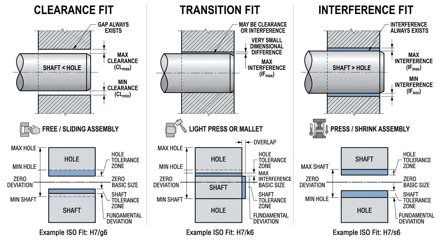
engineering fits: clearance fit, transition fit, and interference fit
Clearance Fit
A clearance fit always produces a gap between assembled parts. The shaft is always smaller than the hole in every combination of conforming dimensions. This gap allows relative motion, rotation, sliding, reciprocation, without binding.
Clearance fits range from very loose (large gap, used for rough alignment and large temperature variation) to close-running (minimal gap, used for precision guided motion with tight dimensional control). The minimum clearance in a clearance fit is a positive number, even at worst-case dimensions, some gap exists.
Transition Fit
A transition fit produces either a small clearance or small interference depending on where actual dimensions fall within their tolerance ranges. No guarantee of gap or overlap, the tolerance zones of hole and shaft overlap.
Transition fits are used for accurate location where the part needs to be positioned precisely and held against minor forces, but where assembly must be possible by hand or light mallet. Locating pins, dowels, and hubs where a keyway carries the torque are typical transition fit applications.
Interference Fit
An interference fit always produces overlap, the shaft is always larger than the hole, requiring press or temperature-differential assembly. The overlap creates radial contact pressure that generates friction holding the joint against axial, radial, and torsional loads.
Interference fits are permanent or semi-permanent joints, the assembled pair resists disassembly forces proportional to the interference magnitude, contact area, and friction coefficient.
Clearance, Transition, and Interference Fit Examples
Clearance Fit Examples
H7/g6, Close-running fit. The most common clearance engineering fit in precision mechanical engineering. Minimum clearance approximately 0.007mm, maximum approximately 0.041mm for 25mm nominal. Used for precision spindles, sliding fits requiring accurate guidance, and any rotating shaft requiring minimal side play. The tolerance on the shaft (g6) is tighter than the hole (H7), acknowledging that shaft grinding achieves better consistency than bore machining.
H9/d9, Free-running fit. Larger clearance for shafts that rotate freely in plain bearings without close guidance requirements. For 25 mm nominal size, H9/d9 provides a substantially larger clearance than H7/g6. Use the ISO 286 limit-deviation table for the exact clearance range at the selected nominal size. Used for commercial-quality rotating equipment, large temperature swings, or contaminant-tolerant applications where some shaft float is acceptable.
H11/c11, Slack fit. Very large clearance for approximate alignment, rough assembly, and applications tolerating significant dimensional variation. For a 25 mm nominal size, H11/c11 provides approximately 0.110 to 0.370 mm of clearance.
Transition Fit Examples
H7/k6, Locational transition. Produces small interference or small clearance depending on actual dimensions. For 25mm: clearance range of −0.015 to +0.019 mm. Assembled pairs require light mallet or press but can be disassembled without damage. Used for gear hubs on keyed shafts, locating bosses on fixture plates, and repeat-assembly components requiring precise location.
H7/n6, Push transition. Slightly more consistent interference bias. For 25mm: −0.028 to +0.006 mm. Needs a press for reliable assembly; hand assembly may be possible at clearance end. Locating pins, coupling halves, and hubs with positive retention.
Interference Fit Examples
H7/p6, Light press. Minimum interference (smallest shaft, largest hole) approaches zero at small sizes, effectively a heavy transition at the lower end. For a 50 mm nominal size, H7/p6 produces approximately 0.001 to 0.042 mm of interference.
H7/s6, Medium drive fit. For a 50 mm nominal size, H7/s6 produces approximately 0.018 to 0.059 mm of interference. Requires hydraulic press for assembly. Used for bushings, coupling hubs, bearing rings in housing, and components requiring permanent retention under moderate service loads.
H7/u6, Force fit. For a 50 mm nominal size, H7/u6 produces approximately 0.045 to 0.086 mm of interference. Heavy press or temperature-differential assembly (shrink fit) required. Used for components requiring maximum retention, impeller hubs, flywheel assemblies, and other permanent high-load connections.
Hole-Basis vs. Shaft-Basis System
| Factor | Hole-Basis | Shaft-Basis |
|---|---|---|
| Fixed feature | Hole at H | Shaft at h |
| Variable feature | Shaft | Hole |
| Common use | General engineering | Standard shaft components |
| Main advantage | Easier shaft adjustment | Preserves standard shaft size |
Hole-Basis System
Hole-basis limits and fits are standard because holes are harder to fine-tune after machining. You can grind a shaft to precise diameter easily. Adjusting a bore after it's been machined requires re-boring or honing, more complex and less practical for fine-tuning. Keeping the hole at H and varying the shaft gives the machining process its most flexible approach.
Shaft-Basis System
In shaft-basis fits, the shaft is fixed at h (upper limit at nominal) and the hole varies. This system is used when the shaft is a standard commercial dimension, ground bar stock at h6, motor output shafts at standard diameters, purchased precision shafts.
Fitting a housing bore to a standard shaft (rather than grinding a shaft to fit a standardized bore) uses the shaft-basis system. The hole designations in shaft-basis use uppercase letters offset from H, G for close clearance, P for light interference, and so on.
When to Use Hole-Basis vs. Shaft-Basis Systems
Use hole-basis for all general engineering design, it's the standard approach, supported by all tooling libraries, tolerance tables, and inspection gauges as defaults.
Use shaft-basis when the shaft is a purchased or standardized component whose diameter cannot or should not be modified, standard bearing shaft diameters, precision ground bar stock used as-purchased, motor shafts specified by the motor manufacturer.
Limits and Fits in CNC Machining
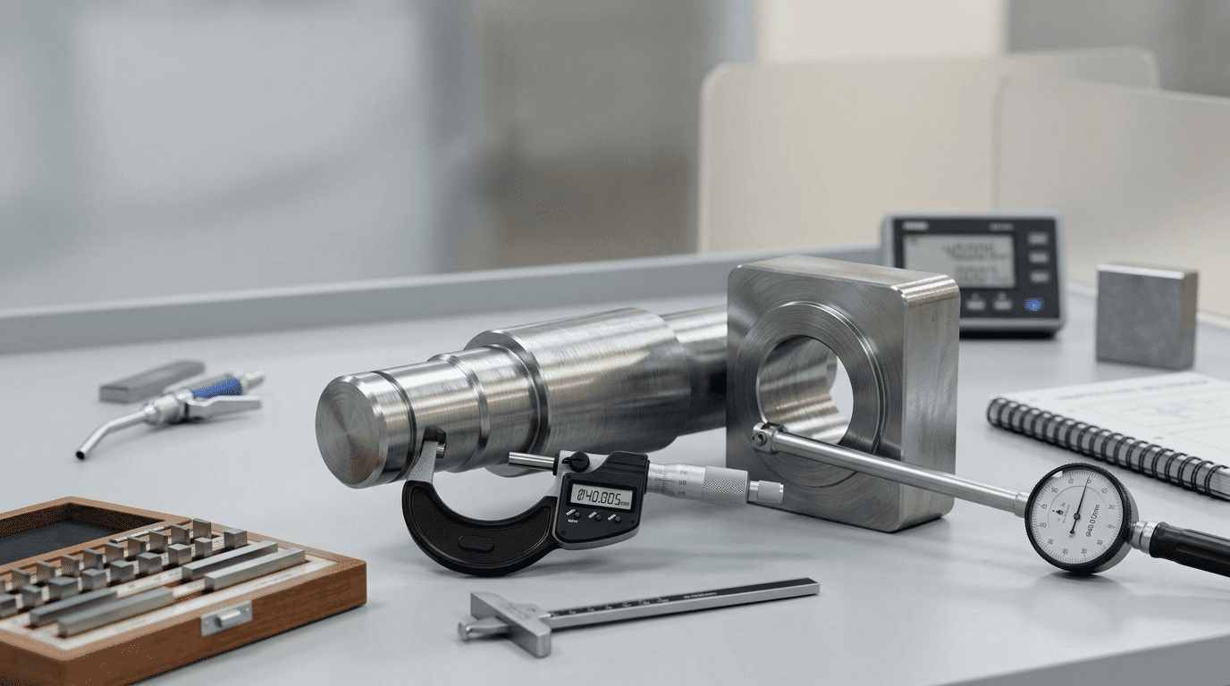
shaft and bearing housing fit inspection
Machining Tolerances and Fit Requirements
Different CNC machining processes achieve different natural tolerance grades. Matching the tolerance fit requirement to an achievable process is fundamental to cost-effective precision machining.
| Process | Typical IT Grade | Dimensional Accuracy | Surface Finish Ra | Common Application |
|---|---|---|---|---|
| CNC milling (standard) | IT9-IT11 | ±0.1-0.5mm | 1.6-6.3 µm | General machined features |
| CNC milling (finish) | IT7-IT8 | ±0.025-0.1mm | 0.8-1.6 µm | Mating faces, precision pockets |
| CNC turning (standard) | IT8-IT9 | ±0.05-0.1mm | 1.6-3.2 µm | General turned features |
| CNC turning (finish) | IT7 | ±0.025mm | 0.8-1.6 µm | Running fits, journals |
| Boring | IT7 | ±0.010-0.025mm | 0.8-1.6 µm | Bearing bores, precision holes |
| Reaming | IT6-IT7 | ±0.005-0.025mm | 0.4-0.8 µm | Precision clearance holes |
| Cylindrical grinding | IT5-IT6 | ±0.005-0.010mm | 0.2-0.4 µm | Shaft journals, precision fits |
| Honing | IT5-IT6 | ±0.003-0.010mm | 0.1-0.4 µm | Precision bores, engine cylinders |
CNC Turning vs. Milling for Tight Fits
Shaft diameters for engineering fits are most efficiently produced by CNC turning, which achieves IT7-IT8 in finish turning and IT5-IT6 in cylindrical grinding. Bore dimensions for hole and shaft fits are produced by boring, reaming, or honing, each progressively finer.
CNC milling can produce bores in prismatic parts through interpolated circular tool paths, but bore circularity and dimensional accuracy in milled bores rarely matches dedicated boring operations for tight-fit applications. For bearing bores and precision clearance fits, a boring operation after milling rough material removal is standard practice.
How Tighter Tolerances Affect Cost
Machining tolerances and fits drive cost nonlinearly:
| Tolerance Class | Relative Cost | Typical Cost Drivers |
|---|---|---|
| IT9–IT11 | Lower | Standard machining and inspection |
| IT7–IT8 | Moderate | Finish passes and tighter inspection |
| IT6 | Higher | Additional finishing and inspection may be required |
| IT5 and finer | High to very high | Precision finishing, controlled measurement, additional process steps |
The cost jump from IT7 to IT6 is significant because it typically moves from CNC boring and reaming to cylindrical grinding, a separate machine, separate setup, and a process with higher per-hour cost.
Processes for Achieving Tight Fits
Achieving IT6 and finer for precision engineering fits consistently requires grinding for shafts and honing for bores. Grinding achieves surface finish of Ra 0.2-0.4 µm alongside dimensional accuracy, critical for bearing surfaces where surface texture affects oil film formation and wear rate. Honing achieves similar accuracy in bores with the additional benefit of producing a cross-hatched surface finish that retains lubricant better than a turned or bored surface.
How to Choose the Right Engineering Fit
Choose a Clearance Fit for Movement
Choose a clearance fit when relative motion is required. Choose a transition fit when accurate location is more important than force transmission. Choose an interference fit when the joint must resist movement or transmit loads through friction.
Precision guided motion (spindles, precision slides): H7/g6 or H7/f7, minimal clearance, accurate guidance. General rotating shafts in plain bearings: H8/f7 or H9/d9, moderate clearance, tolerates some imprecision. Rough alignment with significant clearance: H11/c11, large gap, tolerates misalignment and contamination.
Choose a Transition Fit for Accurate Location
If parts must be positioned accurately without requiring force for assembly and without carrying significant loads through the fit itself (torque is carried by a key, pin, or fastener), a transition fit provides accurate location with hand or light mallet assembly.
Easy, repeatable location: H7/h6, near-zero clearance or tiny interference, hand-assemblable. Positive location, occasional disassembly: H7/k6, small interference or clearance, light mallet. Firm location, infrequent disassembly: H7/n6, consistent small interference, press required.
Choose an Interference Fit for Rigid Assembly
If the fit must provide retention force, holding a bushing in a housing, transmitting torque through the fit itself, securing a coupling hub, an interference fit is required. Selection within interference fits depends on required retention force, assembly method, and material.
Light retention, possible disassembly: H7/p6, minimal interference. Permanent assembly, moderate loads: H7/s6, medium interference, press assembly. Maximum retention, high loads: H7/u6, heavy interference, shrink or press assembly.
How to Specify Limits and Fits on Engineering Drawings
Reading an H7/g6 Fit
The notation 25 H7/g6 on an engineering drawing communicates the complete limits and fits specification for a 25mm nominal diameter mating pair. Reading it:
25, nominal size in millimeters (the starting dimension for all limit calculations) H, hole fundamental deviation: lower limit at nominal, tolerance zone extends above 7, IT grade for the hole: tolerance band width = 0.021mm at 25mm (from ISO 286 tables) g, shaft fundamental deviation: small negative offset below nominal 6, IT grade for the shaft: tolerance band width = 0.013mm at 25mm
A drawing callout such as 25 H7/g6 combines the nominal size with the hole and shaft tolerance classes. H7 defines the hole tolerance zone, while g6 defines the shaft tolerance zone.
Limits and Fits Notation
Drawings can specify engineering fits in three ways, all conveying the same information:
Fit designation only: Ø25 H7/g6, requires the reader to look up limit dimensions
Limit dimensions with designation: Ø25 H7/g6 (25.000/25.021) for the hole; (24.993/24.980) for the shaft
Limit dimensions only: Ø25 (+0.021/0.000) for the hole; Ø25 (−0.007/−0.020) for the shaft
Option 2 is the most practical for manufacturing, the designation tells the engineer what fit class was intended (useful for substitution decisions) and the limits tell the machinist and inspector exactly what to make and measure without table lookups.
Common Limits and Fits Drawing Mistakes
Incorrect limit dimensions for a fit designation
Applying an H7/g6 designation but stating limit dimensions that don't match ISO 286 for that nominal size. The machinist follows the numerical limits; the engineer follows the intended fit. The two specifications must agree.
Using fit designations without explicit limits
Drawings sent to unfamiliar machine shops should state both the fit designation and the actual limit dimensions. Not every shop will have the relevant ISO 286 tables readily available.
Using the wrong hole-basis or shaft-basis notation
Applying hole-basis notation to a shaft-basis situation without changing the letter codes can produce a specification that's technically formatted correctly but wrong in design intent.
Failing to identify the mating feature
On drawings with multiple mating features, the fit callout must clearly identify whether it applies to the hole or shaft. Use unambiguous leader lines so there's no doubt which dimension carries the designation.
Limits and Fits vs. GD&T
| Factor | ISO 286 | ASME B4.1 |
|---|---|---|
| Primary system | Metric tolerance classes | Preferred cylindrical fits |
| Designation | H7/g6 | RC, LC, LT, LN, FN classes |
| Main use | ISO dimensional fit system | Preferred limits and fits |
Apply limits and fits whenever two parts mate, whenever the size relationship between a hole and shaft determines whether the assembly functions correctly. Every mating diameter pair in a machine assembly needs an engineering fit specification, not just a general ±0.1mm title block tolerance.
For more on how GD&T and dimensional tolerances work together in engineering drawings, see the GD&T flatness guide and the straightness GD&T guide, both of which address the geometric controls that appear alongside dimensional fit specifications on precision CNC part drawings.
Dimensional Tolerances vs. Geometric Tolerances
Limits and fits control size, the diameter of a bore, the diameter of a shaft. They don't control whether the bore is round, whether it's straight along its length, or whether it's positioned correctly relative to other features.
GD&T controls geometry, cylindricity (is the bore round and straight?), perpendicularity (is the bore axis at 90° to the face?), position (is the bore in the right location relative to the datum scheme?). GD&T doesn't directly control size.
Precision engineering requires both. A bearing bore specified H7 may also require form and orientation controls, depending on the bearing, loading conditions, assembly requirements, and functional tolerance of the application. Without the cylindricity control, an H7 bore could be dimensionally conforming but elliptical, and the bearing would rock.
How Limits and Fits Work with GD&T
A complete drawing for a precision bearing bore typically includes:
Dimensional tolerance (H7 limits): controls the bore diameter
Cylindricity tolerance (GD&T): controls bore roundness and straightness
Perpendicularity (GD&T): controls bore axis orientation relative to a face datum
Surface finish (Ra): controls texture for bearing seating
Limits and fits provide the size specification. GD&T provides the geometric specification. Both are required for a complete, unambiguous definition of what the feature must be.
Conclusion About Limits and Fits
ISO 286 provides a standardized way to define hole and shaft tolerance zones and the resulting clearance, transition, or interference fit. The key is to select a fit based on movement, location, retention, assembly method, and manufacturing capability.
ISO 286 encodes decades of manufacturing experience into a standardized notation that communicates complete hole and shaft fit specifications in compact form. H7/g6, H7/k6, H7/s6, each of these fit designations completely specifies the tolerance zone for both mating parts and the resulting assembly relationship.
At JLCCNC, limits and fits specifications are reviewed before production on every precision order to confirm the specified IT grade matches the planned process capability, and that inspection methods are appropriate for the tolerance class.
Upload Your Files for Engineering Review and Quote at JLCCNC
Precision CNC Machining Service
Professional manufacturing, fast turnaround, and quality assurance.
FAQs About Limits and Fits
Q: What are limits and fits?
Limits and fits is an engineering system for specifying the acceptable size range for mating mechanical features, primarily holes and shafts, and the dimensional relationship (clearance, interference, or transition) that results when those features are assembled. The limits are the upper and lower acceptable dimensions for each feature; the fit describes how those limits combine to define the assembly relationship.
Q: What are the three types of engineering fits?
The three types of engineering fits are clearance fit (shaft always smaller than hole, a gap always exists, allowing relative motion), interference fit (shaft always larger than hole, overlap always exists, requiring forced assembly and providing retention force), and transition fit (tolerance zones overlap, some assembled pairs have clearance, others have interference depending on actual dimensions).
Q: What is the difference between a clearance and interference fit?
In a clearance fit, every assembly combination produces a gap, minimum clearance is positive even at worst-case dimensions. In an interference fit, every assembly combination produces overlap, minimum interference is positive even at worst-case dimensions. The difference is in the relationship between the shaft and hole tolerance zones: clearance fit zones don't overlap (shaft zone is entirely below hole zone); interference fit zones don't overlap in the other direction (shaft zone is entirely above hole zone).
Q: What does H7/g6 mean?
H7/g6 is an ISO 286 fit designation for a close-running clearance fit. H7 specifies the hole: H means zero lower deviation (lower limit at nominal size), 7 is the IT grade. g6 specifies the shaft: g means a small negative deviation (shaft is below nominal), 6 is the IT grade. H7/g6 is a common ISO 286 clearance fit. The H7 hole remains above the g6 shaft throughout the specified tolerance zones, so every conforming assembly has clearance.
Q: What is the hole-basis system?
The hole-basis system fixes the hole at H and varies the shaft tolerance to achieve the required fit. It is widely used because shaft dimensions are often easier to adjust than finished bore dimensions.
Q: How are limits and fits used in CNC machining?
Limits and fits drive process selection in CNC machining. Standard CNC turning and boring achieves IT7-IT8, adequate for most general precision fits. IT6 requires cylindrical grinding for shafts and precision boring or reaming for holes. IT5 and below requires dedicated precision grinding and temperature-controlled measurement. Tighter machining tolerances and fits cost significantly more due to additional process steps, slower machining rates, and more rigorous inspection requirements — the cost increase is nonlinear as IT grade tightens.
Keep Learning
Circularity GD&T Explained
Key Takeaways Circularity controls how round each cross-section is on a cylindrical, conical, or spherical surface. Each cross-section is checked separately. Circularity doesn't control taper, axis straightness, or alignment between sections. No datum is needed because circularity controls the shape of the feature itself. The circularity tolerance zone is bounded by two concentric circles whose radial separation equals the specified tolerance. Each circular element must fit within its own zone, evalua......
Press Fit Tolerance: Interference, Charts & Design Guide
Key Takeaways A press fit is an interference fit: the shaft is larger than the hole, and elastic deformation of the mating parts after assembly creates contact pressure that generates the friction holding the joint together. Press fit interference is the difference between the shaft diameter and the hole diameter. Minimum interference uses worst-case dimensions for the smallest overlap. Maximum interference uses worst-case dimensions for the largest overlap. Press fit tolerance is selected based on re......
GD&T Datum: Definition, Types, Symbols, and Datum Reference Frame
Key Takeaways A datum in GD&T is a theoretically exact reference used to locate or orient other features on a part. It is not the physical surface itself. A datum feature is the physical feature identified on the part and used to establish a datum. The datum itself is the theoretically exact geometric reference derived from that feature. Datums become especially important when several features have to work together. A hole pattern, bearing bore, mounting face, or mating surface may need to establish t......
GD&T Runout: Definition, Symbol, Measurement & Tolerance
Key Takeaways Runout limits surface variation while a part rotates around its specified datum axis. The datum feature establishes the axis used for the runout requirement. You compare the full indicator variation during rotation with the tolerance stated on the drawing. Circular runout applies at individual circular sections of the controlled surface. Total runout evaluates the controlled surface across its specified extent. Runout is not a size tolerance, and its value is not determined by the diamet......
GD&T Perpendicularity: Definition, Tolerance & Examples
Key Takeaways Perpendicularity is an orientation control used for a feature specified at 90° to a datum. A surface callout controls the complete surface within two parallel planes set perpendicular to the referenced datum. An axis callout controls the derived axis inside the specified tolerance zone instead of controlling the physical surface directly. Perpendicularity does not establish the location of a feature. A drawing can require another geometric control when position also needs definition. Dat......
Concentricity in GD&T: Definition, Symbol, Tolerance, and Measurement
Key Takeaways Concentricity in legacy ASME GD&T controls the derived median points of a feature relative to a datum axis. It does not simply compare the axes of two fitted cylinders. Check the drawing standard first. Legacy ASME concentricity and ISO concentricity or coaxiality should not be interpreted as equivalent requirements. For the cylindrical example in this guide, the tolerance zone is a cylinder centered on the datum axis. The derived median points of the controlled feature must lie within t......