Sheet Metal Forming: Processes, Types, Materials, and Uses
29 min
- What Is Sheet Metal Forming?
- How Does the Sheet Metal Forming Process Work?
- Types of Sheet Metal Forming
- Sheet Metal Forming Machines and Equipment
- Materials Used in Sheet Metal Forming
- Factors That Affect Sheet Metal Forming Quality
- Common Sheet Metal Forming Defects
- Applications of Sheet Metal Forming
- Advantages and Limitations of Sheet Metal Forming
- CNC Sheet Metal Forming
- Sheet Metal Forming Design Considerations
- FAQs About Sheet Metal Forming
Key Takeaways
- Sheet metal forming shapes metal without removing material, the metal deforms plastically into a new geometry while its mass stays essentially constant.
- The main sheet metal forming types are bending, deep drawing, stamping, roll forming, stretch forming, hydroforming, and spinning, each suited to different part geometries, production volumes, and material requirements.
- Formability, how readily a material deforms without cracking or thinning excessively, is the key material property in sheet metal forming, and it varies significantly between alloys, tempers, and thicknesses.
- Springback, wrinkling, tearing, and thinning are the defects that cause the most production problems, and all of them trace back to material properties, tool geometry, and process parameters that should be addressed during design.
- CNC-controlled forming equipment has made complex multi-step forming operations repeatable at production volumes that manual setups simply couldn't achieve consistently.
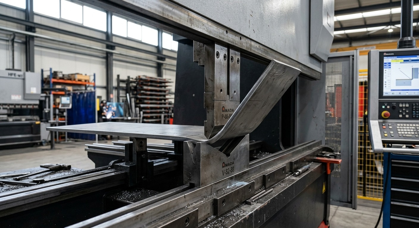
sheet metal forming in a modern fabrication shop
Most of what surrounds you in modern life started as a flat piece of metal. The body panel on your car. The housing of your washing machine. The ductwork running through your ceiling. The enclosure on the server rack in the data center. Every one of these components went through some type of sheet metal forming process to get from a flat blank to the shape it holds right now.
What makes sheet metal forming interesting, and genuinely useful to understand, is the variety of it. Bending is one type of forming, but so is deep drawing, stamping, hydroforming, roll forming, and spinning. Each process works differently, suits different geometries, and produces different results in different materials. Knowing which is which, and why you'd choose one over another, is what this guide is for.
What Is Sheet Metal Forming?
Sheet metal forming is a manufacturing process that changes the shape of a flat metal sheet into a three-dimensional part by applying mechanical force, without removing material, without joining separate pieces, and without significantly altering the metal's mass or composition. The raw material goes in flat and comes out shaped. What happens in between is controlled plastic deformation.
That's the core of it. The force applied must exceed the material's yield strength to produce permanent change. Below that threshold, the metal deforms elastically and springs back. Once the yield strength is exceeded, the deformation becomes permanent, and the metal retains its new shape. Every sheet metal forming process is essentially a controlled way of making that happen precisely, repeatedly, and without causing the kind of damage (cracking, tearing, excessive thinning) that makes the part unusable.
How Does Sheet Metal Forming Work?
The forming process applies controlled force to deform the sheet beyond its elastic range while keeping strain within the material's forming limits. Tool geometry, material properties, lubrication, and process parameters determine how the sheet flows and whether defects such as cracking, wrinkling, or excessive thinning occur. Different methods control this deformation in different ways, from localized bending to material flow in deep drawing and pressure-assisted forming.
Sheet Metal Forming vs. Sheet Metal Fabrication
These terms get used interchangeably and they shouldn't.Sheet metal fabrication is the broader category. It includes cutting (laser cutting, plasma cutting, and punching), joining (welding and riveting), finishing (coating and deburring), and forming. Sheet metal forming is specifically the subset of fabrication that changes sheet geometry through plastic deformation. Bending a bracket is forming. Laser cutting the blank is fabrication but not forming. Welding two bent parts together is fabrication but not forming.
Sheet Metal Forming vs. Metal Cutting
Forming and cutting are opposites in one key sense. Cutting removes material to create geometry. A laser, for example, cuts away material to produce the required profile. Forming creates geometry without removing material, the same mass that went in comes out, just in a different shape. This distinction matters for material utilization, structural integrity (a formed corner retains continuous material and avoids a separate joint, which can simplify the structure and eliminate a weld at that location.), and the types of geometries each approach can achieve.
Need Sheet Metal Bending or Forming?
JLCCNC offers sheet metal bending and forming services for prototypes and production parts, with CNC-controlled equipment for repeatable results across different materials and geometries.
Have a part in mind? Upload your design to JLCCNC and get a quote for your next sheet metal project.

Precision Sheet Metal
Professional manufacturing, fast turnaround, and quality assurance.
How Does the Sheet Metal Forming Process Work?
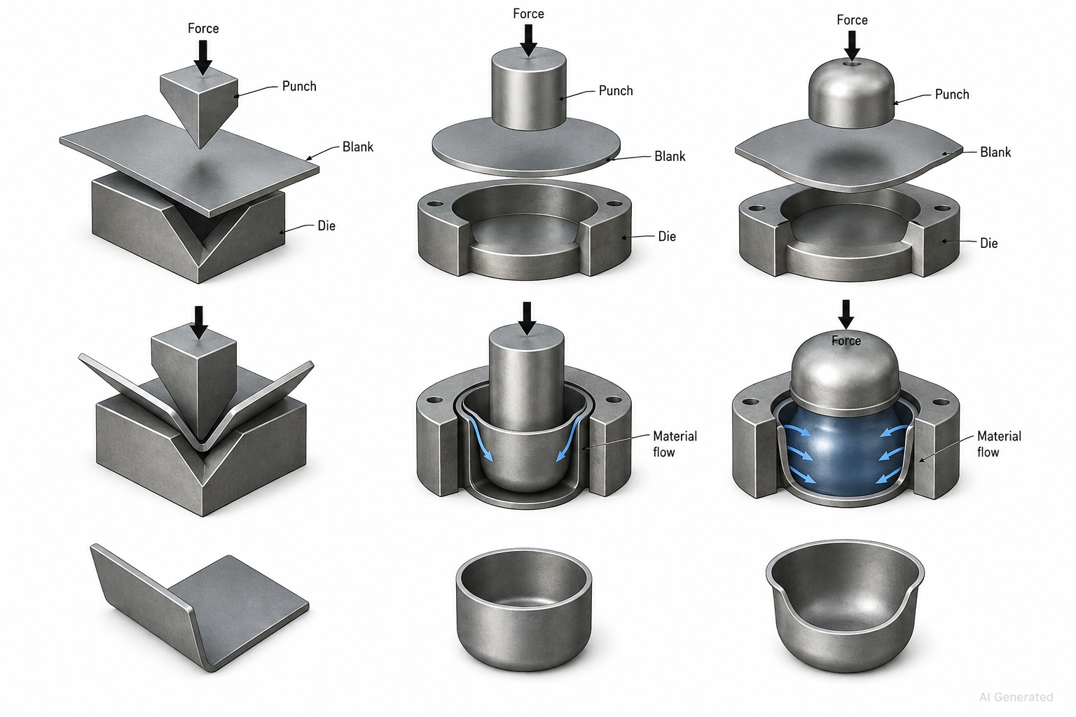
basic mechanics of sheet metal forming.
Part Design and Material Selection
Select the material and forming method together with the required geometry. Formability, thickness, bend or draw requirements, and production volume all affect process selection. Establish these constraints before finalizing the part design to reduce forming problems during production.
Blank Preparation
The flat blank is cut from sheet stock, by laser, waterjet, punching, or shearing depending on the geometry, material, and volume. For simple rectangular blanks, shearing is fast and cheap. For complex profiles with cutouts, laser cutting is the standard. The blank dimensions must account for the material that will stretch, compress, and redistribute during forming, particularly for deep drawing where blank size directly determines whether the part forms correctly or tears.
Tool and Die Setup
Sheet metal forming tools, punches, dies, draw rings, blankholder, forming rolls, position the blank and apply the forming force. Setup quality directly determines part quality. A die that's not aligned properly produces parts that are dimensionally inconsistent. Dies without adequate clearance for the material thickness cause cracking at the cutting edges. For complex forming operations, the setup includes checking lubrication application, blankholder force, and punch-to-die clearances before running any production.
Forming the Sheet Metal
The actual forming operation varies completely depending on the process. A press brake stroke takes a fraction of a second. A deep draw might take multiple seconds of controlled punch travel with precise force management throughout. A roll forming line runs continuously at high speed. What they share is the requirement for controlled, consistent force application, inconsistent force means inconsistent parts.
Inspection and Finishing
After forming, parts get checked against dimensional requirements. Simple bends use digital angle gauges and calipers. Complex drawn or stamped parts may need CMM inspection of critical features. Surface condition is checked for cracks, thinning, wrinkling, or tool marks that indicate process problems.
Post-forming operations commonly include deburring, trimming (particularly for drawn parts where the blank edge deforms and needs to be trimmed to a clean edge), heat treatment for springback relief in some materials, and surface finishing before assembly or coating.
Types of Sheet Metal Forming
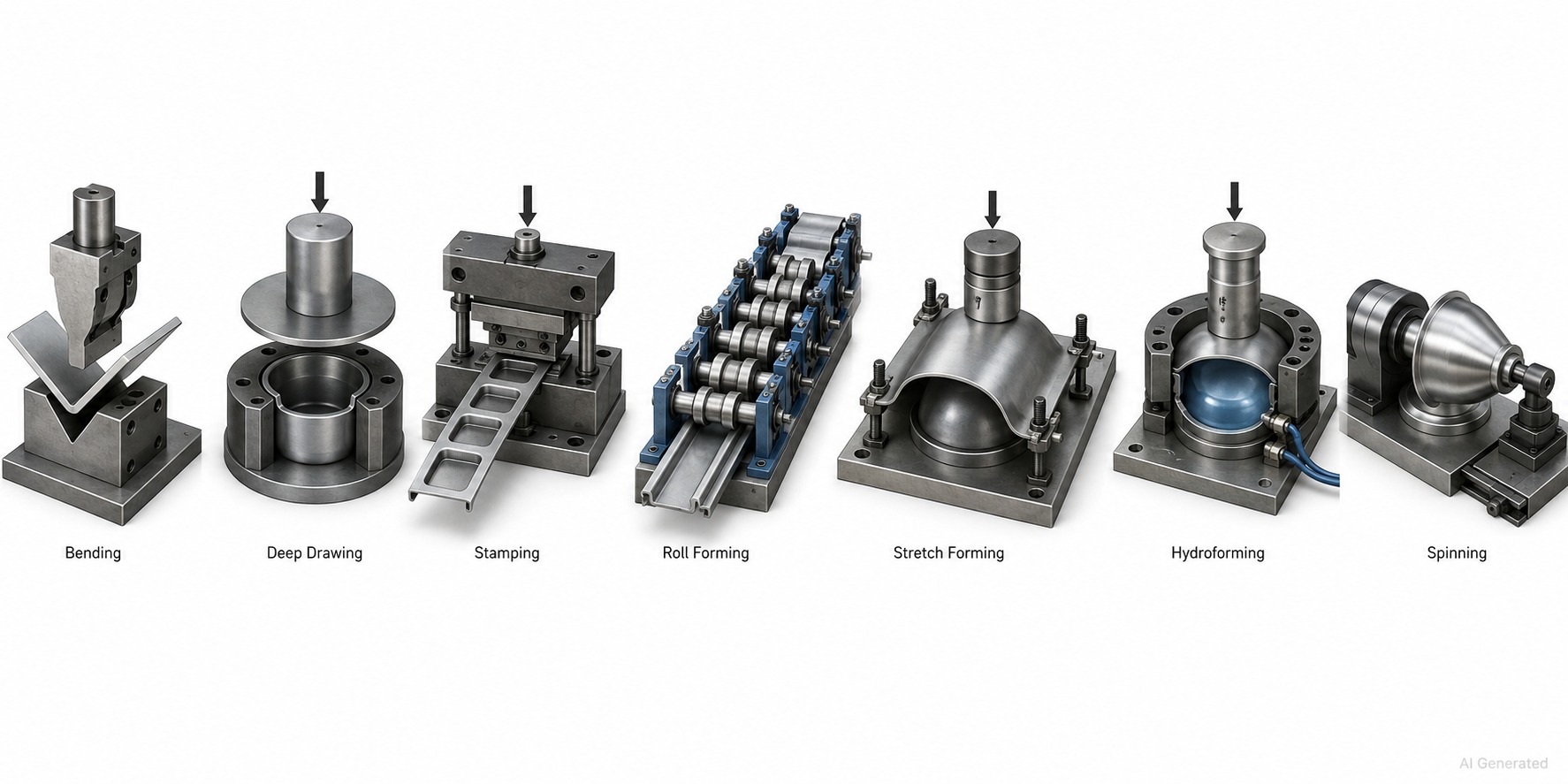
seven major sheet metal forming processes
| Process | Basic Principle | Part Geometry | Volume Suitability | Tooling Cost |
|---|---|---|---|---|
| Bending | Angular deformation along a bend line | Flanges, channels, brackets, boxes | Any volume | Low-Medium |
| Deep Drawing | Blank drawn into die cavity by punch | Cups, cans, housings, shells | Medium-High | High |
| Stamping | Die set punches/forms complex shapes in one stroke | Complex 2D/3D parts | High volume | High |
| Roll Forming | Continuous bending through successive roll stands | Long constant cross-section profiles | High volume | Medium |
| Stretch Forming | Sheet stretched over a die under tension | Large gently curved panels | Medium | Medium |
| Hydroforming | Fluid pressure forms sheet against die | Complex curves, tubes | Medium | Medium-High |
| Spinning | Rotating blank pressed against mandrel | Circular symmetrical shapes | Low-Medium | Low |
Bending
The most common sheet metal forming process in general fabrication. A punch and die deform the sheet along a straight line to produce angular geometry, flanges, channels, boxes, brackets. Bending doesn't require expensive dedicated tooling for each part profile, which is why it suits everything from one-off prototypes to high-volume production.
The three main bending methods—air bending, bottoming, and coining—trade process flexibility against dimensional accuracy and springback control. Air bending uses the same V-die for many different angles, bottoming presses the material fully against the die for better accuracy, and coining can greatly reduce springback, but it requires substantially higher forming force.
Deep Drawing
Deep drawing pulls a flat blank into a die cavity using a punch, transforming it into a cup, shell, or hollow three-dimensional part. The material flows inward from the blank's outer edge toward the die cavity as the punch descends, compressing circumferentially and stretching radially to accommodate the geometry change.
The draw ratio, commonly expressed as the blank diameter divided by punch diameter, is an important factor in determining whether a draw can be completed in a single operation. Too high a draw ratio and the material tears at the punch radius rather than flowing into the die. Multiple progressive draws with annealing between operations achieve deep parts that a single draw couldn't.
Deep drawing is what makes cylindrical housings, beverage cans, cartridge cases, kitchen sinks, and automotive fuel tanks practical at production volume. The tooling investment is significant, matched punch and die sets, blankholders, draw rings, but the per-part cost at volume is very low once the tooling is amortized.
Stamping and Press Forming
Stamping combines multiple sheet metal forming operations, blanking, piercing, bending, drawing, coining, into a single die set that executes them all in one press stroke or in progressive stages as the strip feeds through the die. Complex parts with holes, multiple bends, and formed features come off the press complete, often at cycle times of a fraction of a second.
The cost of stamping tooling is high, Complex progressive dies can require substantial upfront investment, particularly for automotive production. The economics only work when volume justifies the tooling investment. Below a certain volume, CNC press brake bending and laser cutting produce the same part more economically even if the per-part cost is higher.
Roll Forming
Roll forming feeds a flat strip through a series of roll stands, each pair of rolls bending the material progressively closer to the final profile. By the time the strip exits the last roll stand, it has the fully formed cross-section, a channel, an angle, a Z-section, a hat profile, a complex structural section.
Roll forming is continuous and fast. It produces constant-cross-section profiles from coil stock at high linear speeds. This makes it efficient for structural sections, window and door frames, shelving profiles, and other long products with repeated cross-sections. Changing to a different profile requires changing the roll sets, significant changeover time, so roll forming is high-volume process by nature.
Stretch Forming
Stretch forming clamps the sheet metal blank at its edges and pulls it in tension while pressing it against a die. The tension prevents wrinkling by keeping the sheet taut throughout forming. This makes stretch forming ideal for large, gently curved panels, aircraft fuselage skins, automotive body panels, architectural cladding, where the curvature is gradual and wrinkling would be a serious defect.
The limitation is that stretch forming isn't suitable for sharp bends or deep features. It works best with gentle curvature across large areas rather than complex three-dimensional geometry.
Hydroforming
In sheet hydroforming, the blank sits against a forming die, and fluid pressure from behind pushes the sheet into the die cavity. The fluid provides uniform pressure across the full surface area, which produces more uniform thinning and better surface quality than a solid punch can achieve on complex shapes.
Tube hydroforming is related but distinct. A metal tube is pressurized internally while axial force is applied to the tube ends, expanding it against a die cavity.
Hydroforming produces complex curved shapes with excellent surface finish and minimal thinning variation, useful in aerospace, automotive, and architectural applications where surface quality and dimensional accuracy of complex curves matter.
Spinning
Metal spinning rotates a circular blank against a mandrel while a forming tool presses the material progressively against the mandrel's surface. The result is a rotationally symmetric part, cones, hemispheres, cylinders, complex trumpet shapes, produced without dedicated punch-and-die tooling.
Because the tooling is simple (a mandrel and a forming roller), spinning is economical at low volumes and for large-diameter parts where stamping dies would be impractically expensive. Cookware, light reflectors, musical instrument bells, and aerospace nose cones are all made by spinning.
Sheet Metal Forming Machines and Equipment
| Machine | Process | Force Type | CNC? | Volume |
|---|---|---|---|---|
| Press Brake | Bending | Hydraulic/Electric ram | Yes | Any |
| Hydraulic Press | Stamping, Drawing | Hydraulic cylinder | Yes | Medium-High |
| Mechanical Press | Stamping | Flywheel/crankshaft | Limited | High |
| Roll Forming Machine | Roll forming | Continuous rolls | Yes | High |
| Hydroforming Press | Hydroforming | Fluid + mechanical | Yes | Medium |
| Spinning Lathe/CNC | Spinning | Rotary + tool force | Yes | Low-Medium |
Press Brakes
The press brake is the standard machine for sheet metal bending, angular forming along a straight line using punch and die. CNC press brakes control punch depth and back gauge position automatically, enabling complex multi-bend parts with consistent angles and flange lengths across production runs. The flexibility of press brake tooling (one machine handles many different parts with tooling changes) makes it the most versatile sheet metal forming machine for general fabrication.
Hydraulic and Mechanical Presses
Hydraulic presses provide controlled, sustained force throughout the ram stroke, important for deep drawing where consistent blankholder force matters throughout the draw. Mechanical presses use a flywheel and crankshaft mechanism to deliver high force at the bottom of the stroke, making them faster than hydraulic presses at equivalent tonnage and suited to high-speed stamping operations.
Punches and Dies
Every sheet metal forming process that uses a press requires matched punch and die tooling. The punch applies the forming force; the die defines the geometry the material is formed against. Clearance between punch and die, typically 5-15% of material thickness, determines whether the tool shears, bends, or draws the material. Wrong clearance produces burrs, cracks, or poor dimensional accuracy.
Roll Forming Machines
A series of paired rolls, each pair bending the strip slightly further toward the final profile. Roll forming machines are specified by the number of roll stands, the maximum strip width and thickness they handle, and the line speed. Setting up a roll forming machine for a new profile involves designing and manufacturing the roll set and adjusting each roll stand, significant upfront work that's amortized across high production volume.
Hydroforming Equipment
A hydroforming press consists of the high-pressure fluid system (depending on the hydroforming process and equipment, forming pressures can reach hundreds of MPa), the forming die, and the press that applies the closing force. Sheet hydroforming uses a rubber diaphragm or direct fluid contact to transmit pressure to the blank. The equipment cost is high relative to conventional presses, which is why hydroforming is used specifically for applications where the process advantages, complex shape capability, uniform pressure, excellent surface quality, justify it.
CNC Forming Equipment
CNC control is now standard on most new sheet metal forming machines, CNC press brakes, CNC roll forming lines, CNC hydroforming presses, CNC spinning lathes. The benefits are the same across all: consistent repeatability, automatic setup from programmed parameters, reduced operator skill dependence, and integration with CAD/CAM systems that generate forming programs directly from 3D part models.
Materials Used in Sheet Metal Forming
| Material | Formability | Relative Strength | Springback | Typical Processes | Key Consideration |
|---|---|---|---|---|---|
| Mild Steel | Excellent | Medium | Moderate | All processes | Most versatile, benchmark material |
| Stainless Steel (304) | Good | Medium-High | High | Bending, drawing, stamping | Work-hardens; needs higher force |
| Aluminum (3003, 5052) | Very Good | Low-Medium | Low-Medium | All processes | Grain direction critical |
| Aluminum (6061-T6) | Limited | High | High | Bending (large radius) | Cracks at tight radii |
| Copper | Excellent | Low | Low | All processes | Very ductile; marks easily |
| Brass | Good | Low-Medium | Low | Bending, drawing, spinning | Good for precision parts |
| Galvanized Steel | Good | Medium | Moderate | Bending, stamping | Zinc coating cracks at tight radii |
| Titanium | Limited | High | Very High | Specialized forming | Hot forming often required |
Carbon and Mild Steel
The reference material for sheet metal forming. Mild steel balances good formability, reasonable strength, predictable springback, and low cost in a way nothing else quite matches at equivalent thickness. It's the benchmark against which other materials are compared, forming force charts, minimum bend radii, die clearance recommendations all start from mild steel and adjust from there.
Higher carbon grades and structural steels form similarly to mild steel at lower quantities but exhibit more springback and less ductility as strength increases.
Stainless Steel
Austenitic grades, 304 and 316 are the most common, form well but work-harden significantly as they deform. Each forming operation makes the material harder, which changes the forming force requirements and can make subsequent operations on the same part more demanding. This work hardening is sometimes actually useful, drawn stainless parts have significantly higher strength than the original sheet because of the work hardening induced by drawing.
The springback of stainless steel is higher than mild steel, requiring larger overbend compensation in bending and more careful process control in other forming operations.
Aluminum
A wide range of alloys with very different formability characteristics. Soft alloys like 3003 and 5052-H32 are very formable, they bend easily, draw well, and handle complex forming. Harder alloys like 6061-T6 have limited formability and crack at tight radii. For many aluminum alloys, bending across the rolling direction can reduce cracking risk compared with bending parallel to it, but the preferred orientation depends on the alloy, temper, and required bend radius.
The low density of aluminum makes it attractive for weight-sensitive applications, but its lower strength per unit thickness means thicker gauge is often needed to achieve structural requirements, which partially offsets the weight advantage.
Copper and Copper Alloys
Copper is one of the most formable common metals, it deforms readily without cracking, allows tight bend radii, and deep-draws cleanly. Brass (copper-zinc alloy) is slightly less ductile than pure copper but still very workable and suitable for precision formed components. Both materials mark easily from tool contact, which matters for appearance-critical parts.
Galvanized Steel
The steel substrate forms like mild steel. The zinc coating adds one constraint: tight bend radii can crack or delaminate the zinc layer, which defeats the purpose of the galvanized coating. Use bend radii appropriate to the steel grade and coating system, and verify tight bends to minimize cracking or delamination of the zinc coating.
Factors That Affect Sheet Metal Forming Quality
Material Thickness
Thickness affects forming force, minimum achievable radius, die clearance requirements, and susceptibility to thinning in drawing operations. Everything in sheet metal forming scales with thickness, forming force tables, die opening widths, minimum flange lengths. Specifying a forming operation without knowing the exact material thickness is like specifying a weld without knowing the base metal.
Material Strength and Ductility
Ductility, the material's ability to deform without fracturing, is the critical forming property. High strength and high ductility don't always coexist. High-strength steels are exactly the opposite of what their name might suggest for forming: stronger, yes, but less formable. The strain the material can accommodate before fracture limits what forming operations are achievable.
Grain Direction
Sheet metal has a preferred grain direction from the rolling process. Formability is higher when forming is done perpendicular to the rolling direction, the grain boundaries can accommodate more deformation before fracturing. Forming parallel to the rolling direction concentrates deformation along the grain boundaries, increasing cracking risk particularly in harder materials.
Bend and Forming Radius
The strain at the outer surface of a bend increases as the bend radius decreases. Below a minimum radius, which depends on material thickness and ductility, the outer surface strain exceeds the material's fracture strain and cracking occurs. In drawing operations, die corner radii and punch nose radii similarly control the local strain conditions that determine whether material flows smoothly or fractures.
Springback
When forming force is released, the elastic component of the deformation recovers. The part springs back toward its original shape by an amount that depends on the material's yield strength-to-elastic-modulus ratio, the forming radius, and the forming method. High-strength steels spring back significantly. Aluminum springs back moderately. Copper and soft brass spring back very little.
Springback must be compensated for in the tooling design, either by overbending the part, by using processes that minimize springback (bottoming, coining), or by designing the die geometry to account for the expected recovery.
Forming Force
Every forming operation requires force proportional to the material strength, thickness, and geometry. Underestimating the required force, specifying a machine that can't generate it, produces incomplete forming or tooling damage. For common forming operations, established calculation methods can help estimate the required force before machine and tooling selection.
Tool and Die Geometry
Die corner radii, punch nose radius, die clearance, blankholder geometry, and draw bead configuration all influence how material flows during forming. A draw die with too-sharp corner radii tears the material. Too-generous radii allow wrinkling. If blankholder force is too low, wrinkling may occur. Excessive force can restrict material flow and increase the risk of tearing. Getting these relationships right is the core challenge in sheet metal forming tool design.
Common Sheet Metal Forming Defects
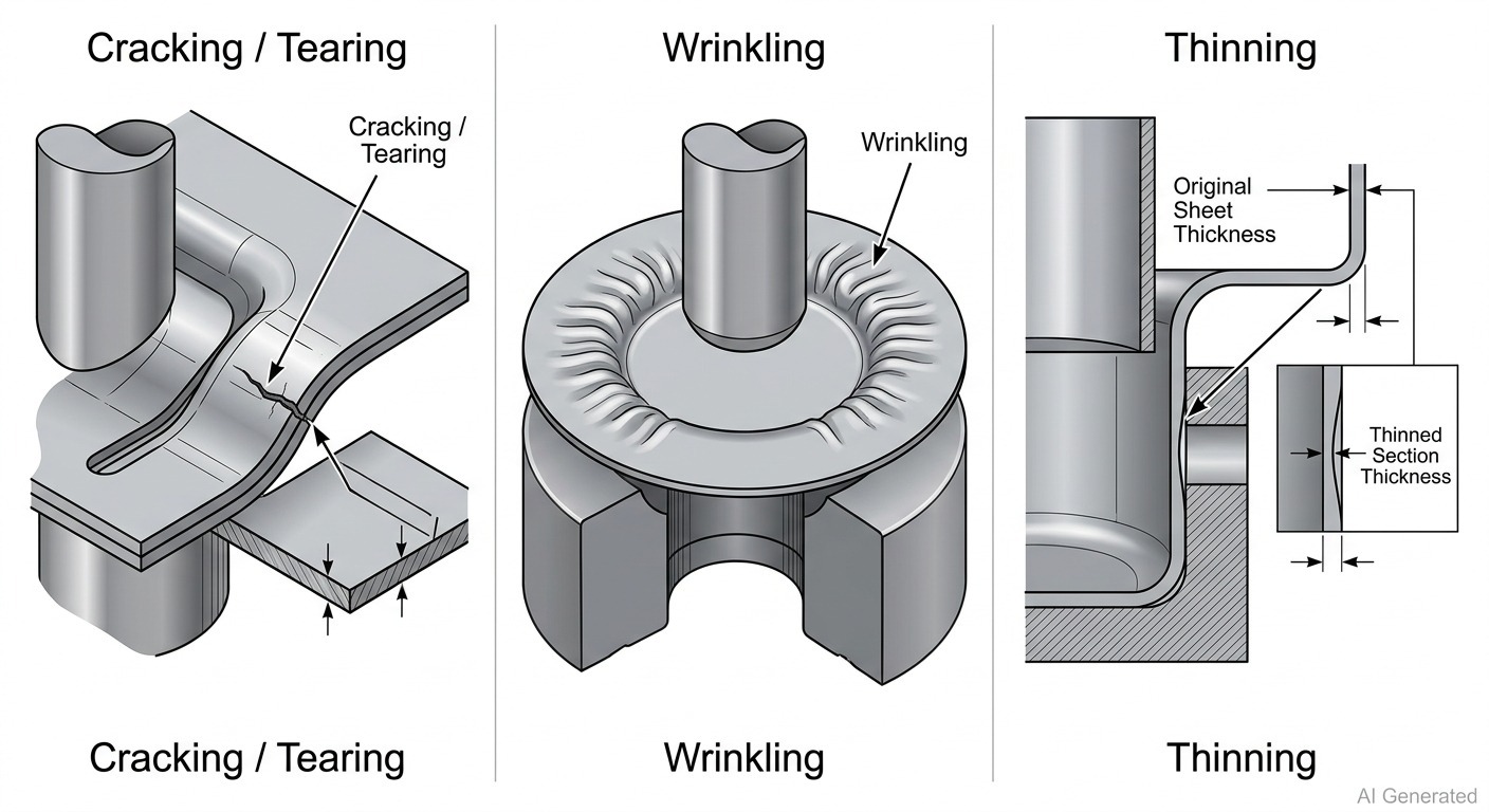
three most important sheet metal forming defects
| Defect | Cause | Prevention |
|---|---|---|
| Cracking / Tearing | Strain exceeds material ductility | Increase forming radius, reduce draw ratio, anneal between operations |
| Wrinkling | Compressive instability in unsupported areas | Increase blankholder force, add draw beads, adjust die geometry |
| Springback | Elastic recovery after forming | Overbend, use bottoming/coining, design springback into tooling |
| Thinning | Excessive stretching in drawn areas | Reduce draw ratio, optimize blankholder force, improve lubrication |
| Distortion | Residual stress imbalance after forming | Balanced tooling design, stress relief, process sequence optimization |
| Tool Marks | Surface contact between tooling and formed part | Polish tooling surfaces, improve lubrication, use protective coatings |
Cracking and Tearing
Cracks in formed sheet metal parts typically occur at locations of maximum strain, the outside of tight bends, the punch nose contact area in deep draws, the draw radius of deep draw dies. The root cause is always the same: local strain has exceeded the material's capacity for plastic deformation without fracture.
Solutions work on the strain side (reduce it by increasing radii, reducing draw ratio, splitting into multiple operations) or the material side (select a more ductile material, anneal between operations to restore ductility, change to a different temper).
Wrinkling
Wrinkling happens when compressive stresses in the sheet exceed the material's buckling resistance in unsupported areas. In deep drawing, the blank flange is under circumferential compression as material flows inward, without adequate blankholder force to stabilize it, it buckles and wrinkles. In bending, excessive material in a flange that's being formed around a curved edge can similarly wrinkle.
The fix is usually more blankholder pressure, draw beads that create controlled resistance to material flow, or geometric modifications that reduce the unsupported area experiencing compression.
Thinning
All sheet metal forming involves some thinning, material thins where it stretches. The problem is excessive, uneven thinning that reduces wall thickness below structurally acceptable levels. In deep drawn parts, thinning concentrates at the punch nose and the die radius. Managing thinning requires balancing the forming forces so the material flows smoothly rather than being stretched excessively at specific locations.
If you're troubleshooting a formed part that's cracking, wrinkling, distorting, or coming out at the wrong angle, here’s a closer look at common sheet metal bending and forming defects and how to prevent them.
Applications of Sheet Metal Forming
| Industry | Typical Parts | Forming Processes | Why Forming |
|---|---|---|---|
| Automotive | Body panels, fuel tanks, structural sections | Stamping, deep drawing, roll forming | High volume, complex geometry, weight efficiency |
| Aerospace | Fuselage skins, ribs, brackets | Stretch forming, hydroforming, bending | Tight tolerances, large curves, lightweight |
| Electronics | Enclosures, chassis, brackets | Bending, stamping | Precision, repeatability, surface quality |
| Industrial | Guards, housings, ducting | Bending, roll forming, stamping | Structural efficiency, fast production |
| Appliances | Washing machine drums, oven bodies, refrigerator liners | Deep drawing, stamping | Complex geometry at volume |
| HVAC | Ductwork, fittings, housings | Roll forming, bending | Long profiles, fast production |
Automotive Components
Car body panels, hood, doors, fenders, roof, are stamped in progressive dies from high-strength steel and aluminum at cycle times of seconds each. Deep drawing produces fuel tanks, oil pans, and wheel housings. Roll forming produces structural sections for doors and sills. Many major exterior body panels are produced from formed sheet metal.
Volume drives the economics here. A door outer panel stamping die costs hundreds of thousands of dollars. But across hundreds of thousands of vehicles, the per-part cost is tiny. Any other manufacturing method at that volume would be significantly more expensive.
Aerospace Components
Aerospace uses stretch forming and hydroforming to produce large, gently curved fuselage skin panels where the combination of precision, surface quality, and low thinning variation matters more than production speed. Bending on CNC press brakes produces ribs, frames, and brackets. The materials are typically aluminum alloys and titanium, both more challenging to form than steel but necessary for the weight and performance requirements.
Electronics and Enclosures
Server chassis, electrical enclosures, instrument panels, and electronic equipment housings are largely CNC press brake bent sheet metal. Precision hole patterns are laser-cut before bending; the formed enclosure provides structural rigidity and EMI shielding from a single material with no secondary fastening at corners. Sheet metal forming produces these at any quantity from one-off prototypes to production runs of thousands.
Advantages and Limitations of Sheet Metal Forming
Advantages
Material utilization is excellent, no material is removed from the blank in forming (unlike machining). The formed part has the same mass as the starting blank, minus any trimmed offcuts.
Structural efficiency is genuinely good. Formed geometry, particularly channels, sections, and drawn shapes, creates stiffness from geometry rather than material mass. A bent channel resists bending far better than a flat plate of equal material weight.
High production rates are achievable with stamping and roll forming. Once tooling is set up, formed parts come off the press or roll line at very high rates. For automotive and consumer products manufacturing, this is exactly what the economics require.
No joining required for complex shapes. A deep drawn housing is a single continuous piece of metal, no welds, no fasteners, no potential failure points at joints.
Limitations
Tooling cost for stamping and deep drawing is significant. Custom progressive dies and draw tooling cost tens to hundreds of thousands of dollars and take weeks to months to manufacture. This investment only makes sense at volumes where the tooling cost amortizes to an acceptable per-part contribution.
Geometry is constrained. Parts must be producible from flat stock, the geometry must be achievable by the forming process without requiring material to appear from nowhere or disappear. Very complex three-dimensional geometry that can't be formed from a flat blank requires casting, machining, or additive manufacturing.
Material limitations exist. Some materials simply don't form well in sheet form, very high-strength steels, brittle alloys, some titanium tempers. These either require specialized forming approaches (hot forming, hydroforming) or aren't suitable for sheet metal forming at all.
Springback requires compensation: Final dimensions may differ from the tooling geometry after unloading, particularly with higher-strength materials.
CNC Sheet Metal Forming
CNC control transformed sheet metal forming from a process heavily dependent on operator skill and setup experience into one where the machine executes programmed forming sequences consistently, automatically, and with documented parameters that can be recalled and repeated months later.
CNC Forming for Complex Parts
Multi-bend parts with tight dimensional relationships between bends benefit most from CNC press brake control. The programmed back gauge positions between bends eliminate the measurement and manual adjustment between operations that makes complex parts slow and inconsistent on manual machines. Offline programming software generates the full forming sequence from 3D CAD geometry, checks for tool collisions in simulation, and outputs the machine program, the operator loads the program and runs first article.
CNC Forming for Prototypes and Production
CNC press brake forming can be cost-effective for prototypes because it generally uses standard tooling rather than dedicated hard dies. A new press brake part goes from design to first-article part in hours, program the bending sequence, set up standard tooling, run the part, check it, adjust, done. The same CNC program that makes the prototype makes production parts. For work that doesn't need stamping tooling volumes, CNC press brake forming handles prototypes and production with the same equipment and tooling.
Accuracy and Repeatability
Modern CNC press brakes hold angle tolerances of ±0.5° routinely in standard production. Dimensional tolerances should be specified according to the drawing requirements and the capabilities of the selected forming process. Tighter tolerances are achievable with first-article verification and bottoming or coining rather than air bending. CNC roll forming maintains consistent cross-section profiles to tight tolerances along long part lengths that manual roll forming couldn't achieve.
Sheet Metal Forming Design Considerations
Material and Thickness Selection
Material and thickness selection should happen before detailed feature design, not after. The forming process constrains both, a material that can't achieve the required bend radius without cracking, or a thickness that requires forming force beyond available machine capacity, means redesigning the part after it's been fully detailed. Match material to the forming process requirements first, then design the part geometry within those constraints.
Minimum Forming Radius
A bend radius around the material thickness can be used as an initial reference for some common sheet metals, but the appropriate minimum radius depends on alloy, temper, thickness, grain direction, and forming method. Harder materials and high-strength grades need larger minimum radii. For drawn parts, die corner and punch nose radii need to be determined from the material properties and draw geometry rather than guessed, too tight and the part tears, too large and control of the drawn geometry suffers.
Holes and Features Near Formed Areas
Holes or cutouts placed too close to bends or drawn areas distort during forming as the material deforms. Keep holes and cutouts sufficiently clear of bend lines to reduce distortion. A common starting guideline is to allow clearance based on material thickness and inside bend radius, then verify it for the specific material and tooling. Features in areas that will be stretched in drawing operations are particularly vulnerable, the thinning and lateral movement of material during drawing shifts feature positions and distorts their geometry.
Bend and Forming Reliefs
At the end of a flange where a bend meets a perpendicular edge or a previously formed feature, material has no room to deform cleanly without tearing. Bend reliefs, small rectangular cutouts at the ends of the bend line, let the material separate at the transition cleanly. Width greater than material thickness, depth past the bend line by at least one material thickness. Add small radii at inside corners of the relief to reduce stress concentration.
Tolerances and Springback
Design tolerances for formed sheet metal parts must be realistic for the forming process being used. Air bent angles are typically ±0.5-1°. Drawn depths vary by ±0.5-1mm depending on material and draw ratio. Specifying tight tolerances (±0.1° on a bent angle, for example) without requiring bottoming or coining doesn't make the tolerance achievable, it just makes the first-article inspection fail.
Springback compensation needs to be built into the tooling, not added as a drawing note. If the part needs to be 90° after forming, the die or process must be designed to achieve 90° accounting for springback, not simply programmed to 90° and expected to arrive there.
Forming Sequence
For parts requiring multiple forming operations, multiple bends, trimming after drawing, secondary formed features, the sequence matters. Features formed early create geometry that constrains what tooling can access for later operations. Some bends can block back-gauge access for subsequent operation. Drawn features that prevent the part from being positioned in secondary tooling. These conflicts are invisible on a flat 3D CAD model but very real on the shop floor. Think through the sequence during design, not after the part arrives at the press.
From straightforward bends and formed brackets to more complex sheet metal geometries, JLCCNC can take your design from CAD to finished parts. Upload your design to JLCCNC today and request a quote for your sheet metal parts.
Precision Sheet Metal
Professional manufacturing, fast turnaround, and quality assurance.
FAQs About Sheet Metal Forming
Q: What is sheet metal forming?
Sheet metal forming shapes flat metal into three-dimensional parts through controlled plastic deformation without removing material. Common methods include bending, deep drawing, stamping, roll forming, and hydroforming.
Q: What are the different types of sheet metal forming?
The main types include bending, deep drawing, stamping, roll forming, stretch forming, hydroforming, and spinning. The best method depends on the part geometry, material, tolerance, and production volume.
Q: What machines are used for sheet metal forming?
Common materials include mild steel, stainless steel, aluminum alloys, copper, brass, galvanized steel, and titanium. Formability varies by alloy, temper, thickness, and forming method.
Q: What materials can be used for sheet metal forming?
The most common sheet metal forming materials are mild steel (most versatile and formable), stainless steel (good formability with higher force requirements), aluminum alloys (very good formability in softer grades, limited in harder tempers like 6061-T6), copper (excellent formability), brass (good workability for precision parts), and galvanized steel (forms like mild steel with care needed at tight radii to protect the zinc coating). Material ductility is the key property, forming requires plastic deformation without fracture, so the material must be capable of the strain the forming process imposes.
Q: What is the difference between sheet metal forming and bending?
Sheet metal forming is the broader category of processes that plastically deform sheet metal. Bending is one type of forming that creates angular deformation, while methods such as deep drawing and hydroforming create more complex three-dimensional shapes.
Popular Articles
• 9 Sheet Metal Cutting Problems and Solutions
• Hole cutting in sheet metal: techniques, tolerances and applications
• Introduction to Sheet Metal Processing: Techniques and Tools for Precision
• Bending and Forming Technology in Sheet Metal Processing
• Laser cutting technology in sheet metal processing
Keep Learning
Galvanized Sheet Metal: Grades, Specs & When to Use It
Galvanized Sheet Metal: Grades, Specs & When to Use It A design engineer specs "galvanized sheet metal" on a drawing and sends it out for quotes. Three shops come back with three different prices, and one of them asks a follow-up question the others didn't: which gauge, which coating class, hot-dip or electro-galvanized? That question is the difference between a part that survives outdoors for fifteen years and one that starts showing rust spots after eighteen months — and it's the kind of detail that......
Custom Sheet Metal Fabrication: How the Process Works From Design to Delivery
Custom Sheet Metal Fabrication: How the Process Works From Design to Delivery A stock enclosure almost fits. The mounting holes are close but not quite right, the depth is half an inch too shallow, and the vendor's next size up is twice the volume you actually need. This is the point where most people start looking into custom sheet metal fabrication — not because they set out to design a part from scratch, but because nothing off the shelf actually solves the problem. Custom fabrication sounds like i......
Sheet Metal Assembly: How Fabricated Parts Come Together
Sheet Metal Assembly: How Fabricated Parts Come Together Cutting and bending gets a lot of attention because that's where a flat sheet visibly turns into a 3D part. But a single bracket by itself rarely finishes the job — most real sheet metal products are assemblies, multiple formed pieces joined into one working unit, and that assembly step is where a lot of designs quietly succeed or fail. A part that measured perfectly on its own can still not fit once it's supposed to mate with three other pieces......
Sheet Metal Bender: Types, Specs & How to Choose the Right Machine
Sheet Metal Bender: Types, Specs & How to Choose the Right Machine Every sheet metal bracket, enclosure, and panel eventually passes through a bender of some kind — that's the machine, not the process. Our guide on sheet metal bending covers how bending actually deforms metal — springback, minimum radius, bend allowance, and the core press brake and CNC press brake setups most shops run. This one goes further into the equipment side specifically: the less common bender types beyond the standard press ......
What Is Galvanized Metal? Process, Types & How It Works
What Is Galvanized Metal? Process, Types & How It Works Leave a piece of bare steel outside for a season and you'll see exactly why galvanizing exists. Rust doesn't wait for dramatic weather — a little humidity and a few weeks is enough to start eating into an unprotected surface. Galvanized metal solves that problem by giving steel a sacrificial layer of zinc that corrodes in its place, and it's done this job well enough that it's become the default choice for anything from highway guardrails to HVAC......
What Is Sheet Metal Fabrication? The Complete Guide
What Is Sheet Metal Fabrication? The Complete Guide Somewhere between a CAD file and a working enclosure sitting on your bench, a flat piece of metal gets cut, bent, joined, and finished into something that actually does a job. That's sheet metal fabrication — and if you've never ordered a part before, the term can feel bigger than it needs to be. Ask five people what "sheet metal fabrication" covers and you'll get five different answers: some think laser cutting, some think welding, some just picture......