Surface Roughness Measurement: How to Measure It Right
20 min
- What Is Surface Roughness Measurement?
- Common Surface Roughness Measurement Methods
- How to Measure Surface Roughness
- Understanding Surface Roughness Measurement Results
- Factors That Affect Measurement Accuracy
- Choosing the Right Surface Roughness Measurement Method
- Common Surface Roughness Measurement Mistakes
- FAQs about Surface Roughness Measurement
Key Takeaways
- Surface roughness measurement quantifies the microscopic peaks and valleys on a machined or processed surface using standardized parameters, Ra being the most common, Rz the most useful for understanding extreme deviations.
- The two main methods for measuring surface roughness are contact measurement using a stylus profilometer and non-contact optical measurement using laser or white light interferometry.
- How to measure surface roughness correctly involves surface preparation, instrument calibration, correct measurement direction selection, and appropriate cutoff length settings, not just pressing a button and reading a number.
- Surface texture measurement results are only meaningful when the correct parameters, cutoff length, and evaluation length match the engineering specification.
- Measurement direction relative to machining lay is one of the most commonly misunderstood aspects of surface roughness measurement and significantly affects results.
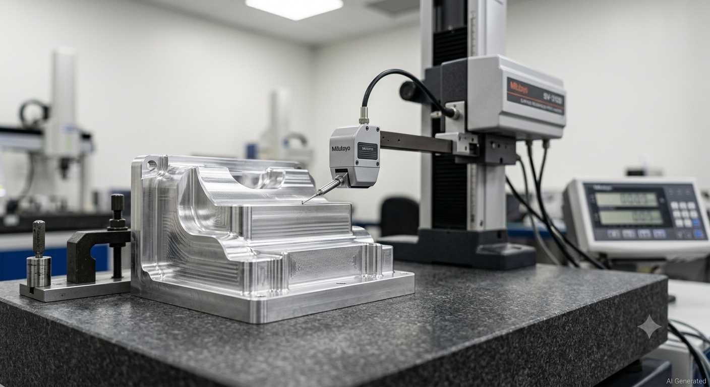
Measuring surface roughness of CNC-machined component
A machined surface may appear smooth while still failing its specified surface roughness requirement. Surface roughness measurement is what separates visual assessment, which is unreliable, from quantified data that can be compared against a drawing requirement, repeated on the next part, and used to make process decisions.
Get surface texture measurement wrong and you either accept parts that will fail in service or reject parts that would have worked fine. Get it right and you have a reliable, repeatable quality check that connects manufacturing process to product performance in a way that no visual inspection can.
Surface finish doesn't happen by accident. It's the result of machining strategy, tooling, cutting parameters, and proper inspection. At JLCCNC, surface roughness verification is part of the manufacturing process, helping ensure critical parts meet both dimensional and surface finish requirements before they leave the shop.

Precision CNC Machining Service
Professional manufacturing, fast turnaround, and quality assurance.
What Is Surface Roughness Measurement?
Surface roughness measurement quantifies the microscopic irregularities left by a manufacturing process. Calibrated instruments measure the peaks, valleys, and other surface features to generate standardized parameters that can be compared with engineering specifications.
The measurement differs from visual inspection or tactile comparison in one fundamental way: it produces numbers. A number that can be specified on a drawing, verified by any qualified laboratory, repeated on subsequent parts, and used to demonstrate that the manufacturing process is producing the required surface texture consistently.
Why Accurate Surface Roughness Measurement Matters
Surface texture measurement outcomes directly affect part performance in ways that go beyond appearance. A bearing journal with too high an Ra wears faster because the surface peaks carry the load on smaller contact areas than a smoother surface would. A sealing face with surface roughness outside specification leaks because the peaks prevent complete contact with the gasket. An optical surface with incorrect surface texture scatters light. A friction surface that's too smooth hydroplanes rather than gripping.
Accurate measurement confirms whether the manufactured surface meets its functional requirements. Inaccurate surface roughness measurement, from wrong settings, dirty surfaces, or misunderstood parameters, tells you nothing useful while appearing to provide verification.
Common Surface Roughness Measurement Methods
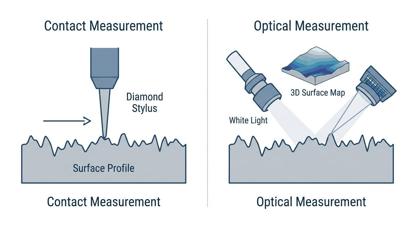
Surface roughness measurement methods
Contact Measurement (Stylus Profilometers)
A stylus profilometer drags a fine diamond-tipped stylus across the surface being measured, and a transducer records the vertical displacement of the stylus tip as it follows the surface profile. The instrument converts this displacement data into the surface roughness parameters specified, Ra, Rz, Rq, and others, based on the profile data collected over the measurement length.
Contact surface roughness measurement is the most widely used method in production environments because stylus profilometers are accurate, well-understood, covered by established standards (ISO 4287, ISO 4288, ASME B46.1), and available as both laboratory-grade instruments and portable handheld devices suitable for shop floor use.
The primary limitation of contact surface texture measurement is the stylus itself. A 2µm radius stylus can't follow valleys narrower than its tip diameter, which means very fine surface texture features may be averaged out rather than fully resolved. On soft materials, copper, gold, soft plastics, the stylus can scratch the surface during measurement.
| Contact Method Characteristics | Detail |
|---|---|
| Stylus tip radius | Typically 2µm or 5µm |
| Vertical resolution | 0.001-0.01µm on laboratory instruments |
| Measuring surface roughness range | Ra 0.01-100µm depending on instrument |
| Advantages | Accurate, standardized, well-proven |
| Limitations | Contact can damage soft surfaces; stylus can't reach into fine internal features |
Non-Contact Optical Measurement
Non-contact surface roughness measurement uses light rather than physical contact to characterize the surface profile. The main technologies are laser displacement sensors, confocal microscopy, white light interferometry, and focus variation microscopy.
White light interferometry is among the most accurate non-contact methods for measuring surface texture, using the interference patterns between a reference beam and a reflected measurement beam to calculate surface height at each measurement point with sub-nanometer vertical resolution. It produces a full 3D surface map rather than just a 2D profile, which is significantly more informative than stylus profilometer data for complex surfaces.
Non-contact measurement is the right approach when the surface can't be touched (risk of damage), when full 3D surface texture measurement is needed rather than a single profile trace, or when measurement needs to happen without fixturing the part rigidly for stylus contact.
| Non-Contact Method | Resolution | Speed | Best Application |
|---|---|---|---|
| Laser displacement | 0.01-0.1µm | Fast | Shop floor, curved parts |
| White light interferometry | <0.01µm | Moderate | Laboratory, precision optics |
| Confocal microscopy | 0.001µm | Slow | Research, very fine surfaces |
| Focus variation | 0.01µm | Fast | 3D surface mapping of rough parts |
Surface Comparison Methods
Surface comparison using visual and tactile comparator specimens, physical reference plates with known Ra values that the measured surface is compared against, is not measuring surface roughness in a quantitative sense, but it's widely used on production floors as a fast, no-instrument check.
The inspector compares the part surface to the comparator specimen by appearance and finger-feel, identifying whether the surface roughness falls roughly within an acceptable range. This method has no numerical output and limited reliability, it's dependent on the inspector's experience and perception. Its value is speed for high-volume screening rather than accuracy for verification of specification compliance.
How to Measure Surface Roughness
-
Step 1: Prepare the Surface
The surface being measured must be clean, dry, and free from cutting fluid residue, contamination, and burrs before surface roughness measurement begins. Contamination on the surface creates false peaks and valleys in the measurement data. Even fingerprints introduce oils that affect stylus contact and can cause false readings. Clean with an appropriate solvent for the material, allow to dry fully, and handle only with clean gloves after cleaning.
For contact surface texture measurement, also check that the surface has no burrs or sharp edges that would catch the stylus during measurement traversal, these can damage the stylus and generate false data spikes that corrupt the measurement.
-
Step 2: Calibrate the Instrument
Calibrate the surface roughness measurement instrument against a reference specimen with certified Ra and Rz values before use. Both stylus profilometers and optical surface texture measurement instruments need regular calibration against certified reference artefacts. Calibration frequency depends on instrument usage and the manufacturer's recommendations. Production instruments are often verified at the beginning of each shift.
Record calibration results. A calibration that's within specification confirms the instrument is measuring surface roughness accurately. Calibration drift outside specification means all measurements taken since the last passing calibration need to be reviewed.
-
Step 3: Select Measurement Direction
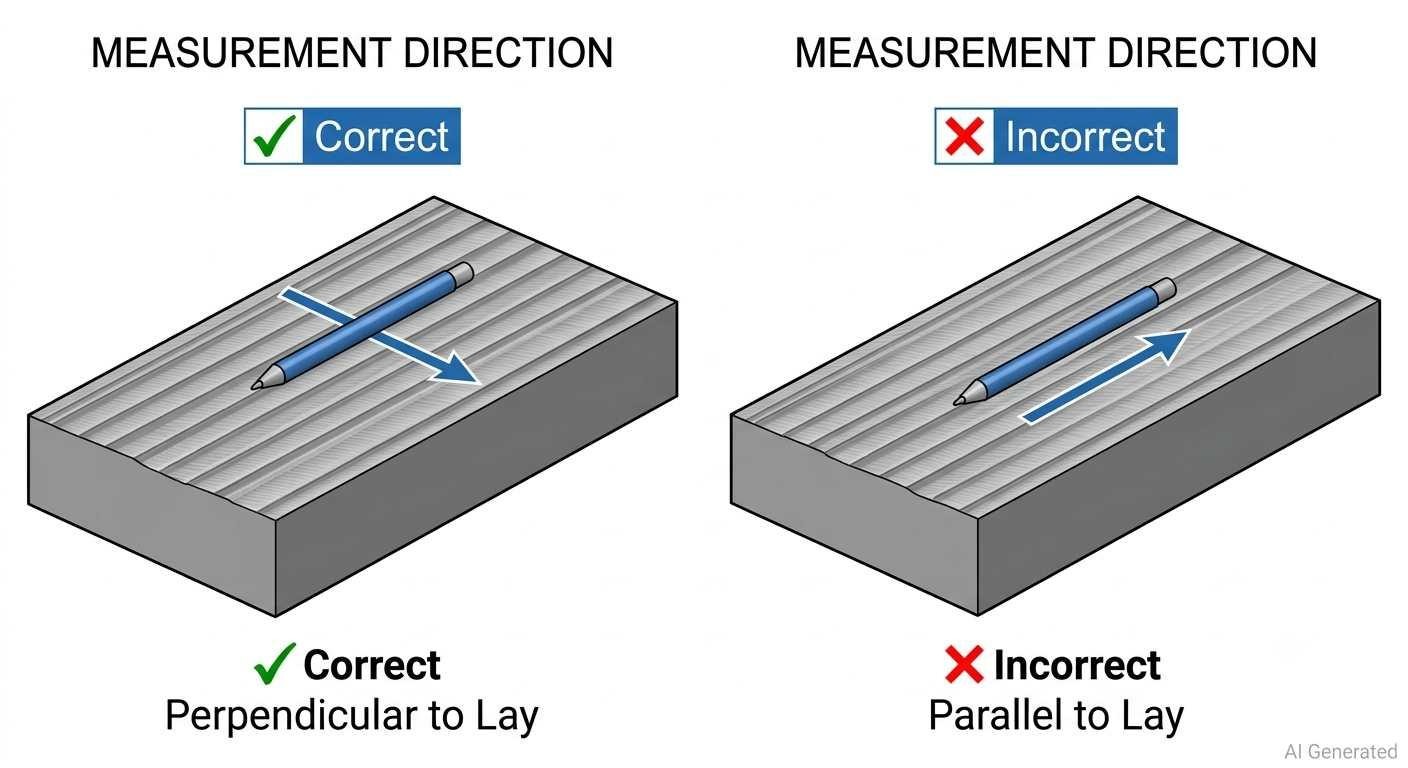
Diagram showing surface roughness measurement direction
Measuring surface roughness in the correct direction relative to the machining lay is critical for obtaining meaningful results. Most machined surfaces have a dominant lay direction, the direction the tool moved, which creates surface features running predominantly parallel to the tool path.
Surface texture measurement should be performed perpendicular to the dominant lay direction to capture the maximum surface roughness values. Measuring parallel to the lay significantly underestimates Ra and Rz because the stylus or optical sensor is following the ridges rather than crossing them. ISO standards specify measuring perpendicular to lay as the default.
For surfaces with no dominant lay (isotropic surfaces from processes like blasting or lapping), measuring surface roughness in multiple directions and averaging gives a more representative result.
-
Step 4: Configure Settings
Set the cutoff length (λc) appropriate for the expected surface roughness range. The cutoff length is the spatial wavelength filter that separates roughness from waviness in the surface profile data. ISO 4288 specifies default cutoff lengths based on Ra range, for example, 0.8mm cutoff for surfaces in the Ra 0.1-2µm range, and 2.5mm cutoff for Ra 2-10µm surfaces.
Using the wrong cutoff length for the surface roughness being measured produces incorrect Ra and Rz values. A cutoff too short excludes real roughness features; a cutoff too long includes waviness that shouldn't be in the roughness measurement. This is one of the most common errors in how to measure surface roughness incorrectly.
Set the evaluation length, typically 5 times the cutoff length per ISO 4288, covering five complete sampling lengths for the measurement.
-
Step 5: Perform Multiple Measurements
A single measurement rarely represents the entire surface. Multiple measurements taken at different locations provide a more reliable assessment of surface roughness. A machined surface has natural variation in Ra across its area, a single measurement captures one location, not the surface as a whole. For surface texture measurement to characterize the surface, take a minimum of three measurements at different locations across the measured surface and average the results.
For critical surfaces where tight roughness specification applies, five measurements at distributed locations across the surface is standard practice. Report the average, the maximum individual value, and the measurement variation, not just the average.
-
Step 6: Interpret Results
Compare the measurement results to the engineering specification on the drawing. Ra is the most commonly specified parameter, verify the measured Ra doesn't exceed the specified maximum. Check Rz if it's specified separately, Rz represents the average of the five largest peak-to-valley heights within the evaluation length and is more sensitive to surface defects than Ra.
Document the results with the parameter values, measurement conditions (instrument, cutoff length, evaluation length, direction), and calibration record. Surface texture measurement results without documentation are not verifiable quality records.
Beyond Surface Roughness
Surface roughness is only one specification on an engineering drawing. Features also need to meet dimensional tolerances and fit requirements. Our Tolerance and Allowance Guide explains how these specifications work together.
Precision CNC Machining Service
Professional manufacturing, fast turnaround, and quality assurance.
Understanding Surface Roughness Measurement Results
Ra, Rz, and Other Common Roughness Parameters
Ra is the starting point for surface roughness measurement results, it gives an overall impression of surface roughness that most engineers are comfortable specifying and interpreting. The limitation of Ra is that it averages all deviations, which means a surface with occasional deep scratches can have the same Ra as a uniformly textured surface with no scratches. For sealing and critical contact applications, measuring surface roughness using Rz as well as Ra catches surface defects that Ra alone misses.
| Parameter | Definition | Typical Application |
|---|---|---|
| Ra | Arithmetic average of absolute surface height deviations from mean line | Most common specification; general surface quality |
| Rz | Average of five largest peak-to-valley heights | Better for sealing surfaces; more sensitive to defects |
| Rq (RMS) | Root mean square roughness | Used in optical applications; statistically more sensitive than Ra |
| Rp | Maximum peak height from mean line | Useful for coating and plating applications |
| Rv | Maximum valley depth from mean line | Useful for lubricant retention evaluation |
| Rt | Total height of profile | Maximum peak to valley over entire evaluation length |
| RSm | Mean width of profile elements | Relates to lay spacing and feature density |
Cutoff Length and Evaluation Length
The cutoff length setting in surface roughness measurement is a filter. It determines which surface height variations are classified as roughness (shorter wavelengths, included) and which are classified as waviness (longer wavelengths, excluded). Setting cutoff length according to the expected Ra range before measuring surface roughness ensures the data correctly represent roughness rather than including form error or waviness.
| Expected Ra Range | ISO 4288 Cutoff Length (λc) | Evaluation Length |
|---|---|---|
| 0.006-0.02 µm | 0.08mm | 0.4mm |
| 0.02-0.1 µm | 0.25mm | 1.25mm |
| 0.1-2 µm | 0.8mm | 4.0mm |
| 2-10 µm | 2.5mm | 12.5mm |
| 10-80 µm | 8.0mm | 40.0mm |
Evaluating Results Against Engineering Specifications
Engineering drawings specify surface roughness using the maximum Ra (or Rz) value the surface must not exceed. A drawing callout of Ra 1.6 µm means the measured Ra must be ≤1.6 µm, not that the surface should be exactly Ra 1.6 µm. Surface texture measurement results below the specified maximum pass; results above fail.
Factors That Affect Measurement Accuracy
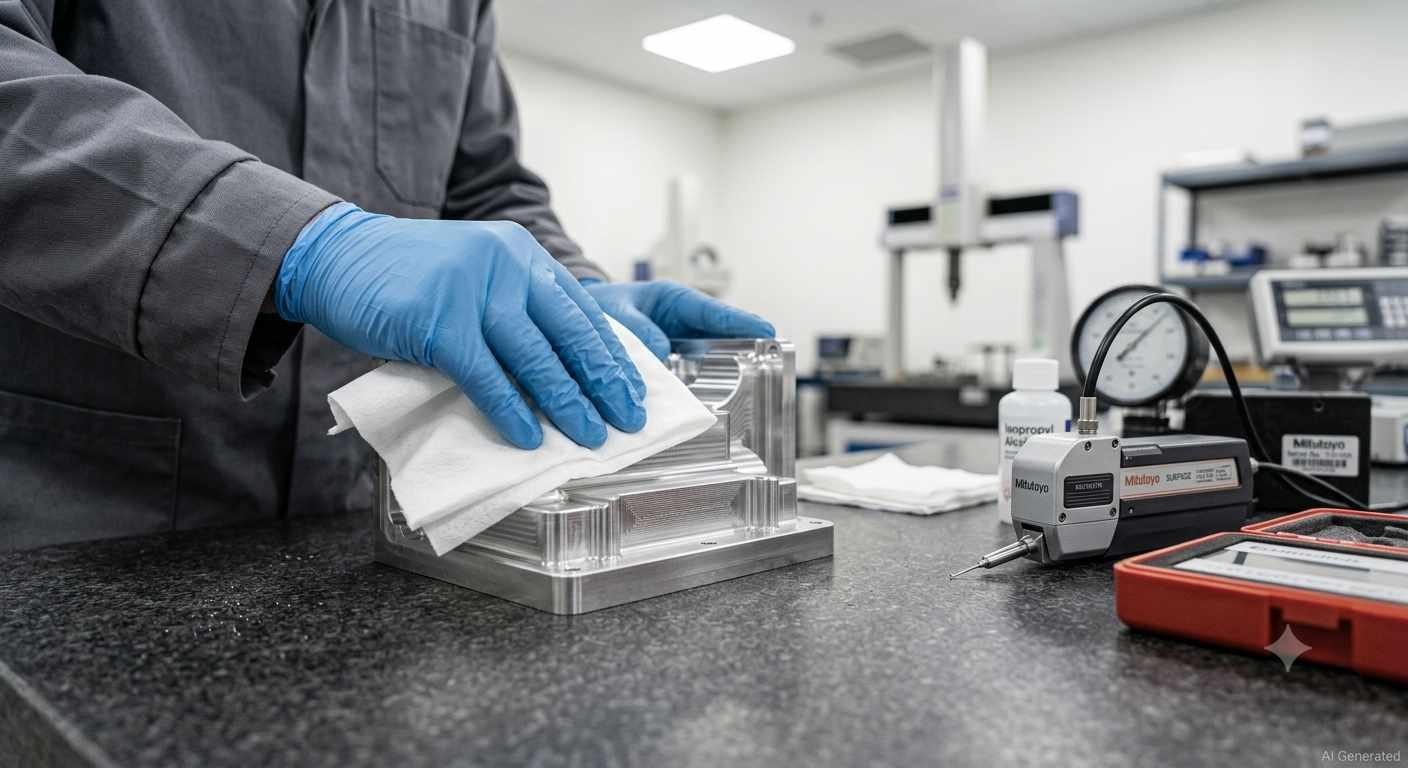
CNC-machined component
Surface Condition and Cleanliness
Contamination is the most common cause of incorrect surface roughness measurement results in production environments. Cutting fluid residue, metal swarf, fingerprint oils, and grinding debris all create false surface features that the instrument measures as real roughness. Clean the surface immediately before measurement and avoid direct handling afterward unless gloves are worn.
Burrs and machining artifacts at the measurement path, not necessarily visible to the naked eye, generate measurement spikes that corrupt Ra and Rz values. Inspect the measurement path visually before contact surface roughness measurement.
Instrument Calibration
An uncalibrated stylus profilometer systematically produces incorrect surface roughness measurement values, consistently high or low depending on the nature of the calibration drift. For calibration to be meaningful for surface texture measurement, it must be traceable to national measurement standards. Reference artefacts used for calibration should themselves have certified values traceable to SI units.
Stylus condition affects the contact measurement accuracy significantly. A chipped or worn stylus tip produces inaccurate surface texture data because the effective tip radius has changed from the calibrated value. The stylus tip should be inspected periodically under magnification for signs of wear or damage.
Measurement Direction and Sampling Length
Measuring surface roughness parallel to lay instead of perpendicular to lay can reduce measured Ra by 50-80% compared to the correct perpendicular measurement. This isn't a calibration error. It's a systematic measurement technique error that produces results that don't characterize the surface correctly.
Sampling length that's too short may not capture enough surface texture features for a statistically valid result. Sampling length that's too long includes form error and waviness in what should be a roughness measurement. Following ISO 4288 cutoff and evaluation length guidance removes this error source from surface roughness measurement.
Environmental Conditions
Vibration in the measurement environment affects both contact and non-contact surface roughness measurement. A stylus profilometer on a vibrating surface plate in a busy machining environment picks up ambient vibration as false surface roughness data. For precision surface texture measurement, an anti-vibration table and a stable measurement environment improve repeatability significantly.
Temperature variation causes thermal expansion of both the part and the instrument, which introduces dimensional drift in surface roughness measurement over time. Laboratory-grade surface roughness measurement should be performed at or near 20°C, the standard reference temperature for dimensional inspection.
Machining Strategy Matters
Even perfectly measured surface roughness cannot compensate for poor machining strategy. Our CNC probing guide explains how accurate workpiece setup improves overall machining consistency before surface finish inspection even begins.
Choosing the Right Surface Roughness Measurement Method
Part Geometry and Accessibility
Most surface roughness measurement methods are suitable for flat, easily accessible external surfaces. Deep internal bores, narrow slots, and small radii restrict stylus access for contact measurement, the stylus arm can't reach, or the required stylus geometry would be too fragile to survive the measurement. For these features, either specialized short-traverse stylus configurations or non-contact optical surface texture measurement provides better access.
Curved surfaces complicate measurement for both contact and non-contact methods. Contact measurement on curved surfaces requires the measurement traverse to follow the surface curvature, modern profilometers can do this with appropriate setup. Non-contact methods may require positioning accuracy that's difficult to achieve on curved surfaces with high local slopes.
Required Measurement Accuracy
Laboratory vs Shop Floor Inspection
Shop floor surface roughness measurement uses portable, robust instruments, handheld stylus profilometers that give Ra readings quickly without complex setup. These instruments sacrifice some accuracy and parameter range for speed, durability, and ease of use in a machining environment. For pass/fail verification of Ra on standard machined surfaces, shop floor surface texture measurement with a calibrated portable profilometer is appropriate.
Laboratory surface roughness measurement uses benchtop profilometers, vibration isolation, controlled temperature environments, and longer evaluation lengths for more complete surface characterization. For first article inspection, process development, and measurement of surfaces with tight tolerances, laboratory measuring surface roughness is the appropriate approach.
Inspection Volume and Efficiency
High-volume production inspection needs measuring surface roughness methods that are fast and consistent without complex setup for every part. Portable stylus profilometers on consistently oriented parts in standard fixtures allow rapid surface texture measurement cycles. Statistical sampling rather than 100% inspection manages the volume while maintaining process control data.
For lower volume, higher precision work where every part needs full surface texture measurement documentation, laboratory-grade surface roughness measurement with full parameter reporting and calibration records is both appropriate and necessary.
| Application Type | Required Accuracy | Recommended Method |
|---|---|---|
| General production verification | ±0.1-0.5 µm | Portable stylus profilometer |
| Precision engineering inspection | ±0.01-0.05 µm | Laboratory stylus profilometer |
| Optical component surfaces | ±0.001-0.01 µm | White light interferometry |
| Research and characterization | Sub-nanometer | Confocal or AFM |
Common Surface Roughness Measurement Mistakes
Using Incorrect Measurement Settings
The most damaging surface roughness measurement error is using the wrong cutoff length for the surface roughness range being measured. An inspector who leaves the profilometer set to 0.25mm cutoff for surfaces that should use 0.8mm cutoff will consistently under-read Ra, a surface at Ra 1.6 µm may measure as Ra 0.8 µm with an incorrect cutoff setting, passing specification when it should fail.
Always verify cutoff length, evaluation length, and filter type match the ISO 4288 specification for the expected Ra range before measuring surface roughness.
Common Settings Error
Using 0.25mm cutoff on a surface requiring 0.8mm can under-read Ra by up to 50%. Always verify cutoff length, evaluation length, and filter type match ISO 4288 for the expected Ra range before measuring.
Measuring Dirty or Damaged Surfaces
Accepting surface roughness measurement results from contaminated or damaged surfaces produces meaningless data that's mistaken for real characterization. The remedy is straightforward: clean the surface thoroughly and repeat the measurement before accepting the result. The error is treating the first measurement from an uncleaned surface as valid.
Damaged reference artefacts used for calibration are an equally serious problem. A calibration artefact with contamination or surface damage produces incorrect calibration data that shifts all subsequent surface texture measurement results systematically.
Misinterpreting Roughness Parameters and Results
Ra is not the only parameter that matters. Accepting a surface based only on Ra while ignoring Rz means accepting surfaces that may have occasional deep scratches or process defects that Ra's averaging property conceals. For critical sealing and contact surfaces, measure surface roughness using both Ra and Rz when the specification includes both.
Treating surface roughness measurement results as exact values rather than estimates with measurement uncertainty is another common misinterpretation. A measured Ra of 0.82 µm from a portable handheld profilometer is not precise to 0.01 µm, the measurement uncertainty of the instrument and the surface variability both contribute to a result that should be interpreted as "approximately 0.8 µm."
FAQs about Surface Roughness Measurement
Q: How is surface roughness measured?
Surface roughness measurement uses either a stylus profilometer (contact method) that drags a fine diamond tip across the surface and records its vertical displacement, or a non-contact optical method like white light interferometry that uses light interference patterns to map surface height. Both methods produce numerical surface roughness parameters, most commonly Ra, that can be compared against engineering specifications.
Q: What is the most common instrument for measuring surface roughness?
The stylus profilometer is the most widely used instrument for surface roughness measurement in production environments. Portable handheld profilometers are common on production floors for rapid Ra measurement, while benchtop laboratory profilometers provide more complete surface texture measurement with full parameter reporting and higher accuracy.
Q: What is the difference between contact and non-contact measurement?
Contact surface roughness measurement uses a physical stylus that touches the surface; non-contact surface texture measurement uses light to characterize the surface without physical contact. Contact methods are well-proven, accurate, and covered by established standards. Non-contact methods are faster for 3D surface mapping, can measure fragile or soft surfaces that stylus contact would damage, and can reach geometries where stylus access is limited.
Q: What is the difference between Ra and Rz?
Ra is the arithmetic average of all surface height deviations from the mean line over the evaluation length, it provides a general indication of surface roughness. Rz is the average of the five largest peak-to-valley heights within the evaluation length, it's more sensitive to surface defects and extreme deviations that Ra's averaging smooths out. For sealing surfaces and surfaces where individual deep defects matter, measuring surface roughness using Rz alongside Ra provides more complete characterization.
Q: What affects surface roughness measurement accuracy?
Surface contamination, incorrect cutoff length settings, measuring in the wrong direction relative to surface lay, instrument calibration condition, stylus wear, environmental vibration, and temperature variation all affect surface roughness measurement accuracy. The most common error sources in production surface texture measurement are contaminated surfaces and incorrect cutoff length settings.
Q: Can surface roughness be measured on curved surfaces?
Yes. Contact surface roughness measurement on curved surfaces requires the measurement traverse to be oriented and the instrument positioned so the stylus follows the surface without the arm geometry limiting travel. Non-contact optical measurement on curved surfaces requires appropriate focusing and positioning. High surface slopes (above approximately 30°) can cause measurement artifacts in some optical surface texture measurement systems.
Q: How do I choose the right surface roughness measurement method?
Choose contact stylus measurement for standard production surface roughness measurement where accuracy to ±0.05-0.1 µm is sufficient and surfaces can be touched. Choose non-contact optical measurement when surfaces can't be touched, when 3D surface texture measurement is required, or when accuracy below 0.01 µm is needed. Use surface comparison for rapid screening when quantitative results aren't required.
Q: Which standards are commonly used for surface roughness measurement?
ISO 4287 defines surface roughness parameters. ISO 4288 specifies rules for the measurement conditions including cutoff length selection. ISO 12085 addresses motif parameters. ASME B46.1 is the equivalent American standard covering surface texture measurement for US applications. ISO 25178 covers areal (3D) surface texture measurement. Engineering drawings should reference the applicable standard to ensure surface roughness measurement is performed consistently.
Precision CNC Machining Service
Professional manufacturing, fast turnaround, and quality assurance.
Conclusion: Surface Roughness Measurement
Surface roughness measurement is a fundamental quality verification step for machined parts, not an optional addition to dimensional inspection. The right method, correctly applied with appropriate settings, produces data that genuinely characterizes the surface, data that connects manufacturing process to product performance in a quantifiable, repeatable way.
Getting surface texture measurement right requires more than owning a profilometer. It requires clean surfaces, calibrated instruments, correct measurement direction, appropriate cutoff length for the roughness range, multiple measurements at distributed locations, and correct interpretation of results against the actual drawing specification.
At JLCCNC, surface roughness requirements are reviewed during DFM, and critical surfaces are verified before production parts are released. Measurement records are maintained where required by the inspection plan.
Popular Articles
• Surface Finish in Machining, Types, Charts & Testing
• Anodizing vs. Hard Anodizing: The Differences in Surface Treatment Techniques
• Anodized Aluminum Colors: Options, Limits, and Real-World Results
• Explanation of different material surface treatment technologies in CNC machining
• How to choose between Laser marking and UV printing?
Keep Learning
Surface Finish in Machining, Types, Charts & Testing
What is Surface Finish in Machining? At its core, surface finish in machining refers to the small-scale irregularities left on the surface of a part after machining. These irregularities are typically grouped into three categories: Roughness: The fine, closely spaced deviations caused by the cutting process itself. Roughness depends heavily on feed rate, tool sharpness, and cutting speed. Waviness: Larger, more widely spaced variations caused by machine tool vibration, deflection, or thermal distortio......
CNC Machining Surface Roughness: A Practical Guide
Why Surface Roughness Matters in CNC Machining When we talk about CNC machining, precision isn't just about hitting the right dimensions, it’s also about how the surface feels and performs. Surface roughness describes the fine irregularities left on a machined surface, and it directly impacts how a part behaves in the real world. So, what is surface roughness? In simple terms, it's the measure of tiny peaks and valleys created by the cutting process. While they might look smooth to the naked eye, thes......
Optimizing Manufacturing Efficiency: A Guide to Computerized Numerical Control (CNC) Machining Surface Finishes
CNC Surface Finishes: Types, Costs, and How to Choose Quick Answer: Choose an as-machined finish when cost and dimensional stability matter most. Use bead blasting or brushing for a uniform cosmetic appearance, anodizing for aluminum corrosion resistance, hard anodizing for wear, and laser marking or UV printing for identification. Confirm material, tolerance, color, masking, and end-use environment before quoting. A CNC-machined part comes off the machine functional but rarely finished — tool marks, ......
Anodizing vs. Hard Anodizing: The Differences in Surface Treatment Techniques
Quick Answer: Choose Type II anodizing when corrosion resistance, color, and cosmetic appearance are the main requirements. Choose Type III hard anodizing when the part needs greater wear resistance and the coating thickness can be accommodated in the fit and tolerance plan. Confirm alloy, coating thickness, color, sealing, and critical dimensions before release. An aluminum bracket for an outdoor enclosure and a hydraulic cylinder rod both might get anodized — but specifying the same process for both......
How to Remove Anodizing from Aluminum Parts
Key Takeaways Chemical stripping is commonly used when anodizing needs to be removed from most or all of an aluminum part, but the process can also attack the underlying aluminum if it is not controlled. Mechanical removal works well for accessible areas but can change the surface texture and remove more base metal than intended. CNC machining gives better control when a defined anodized area needs to be removed from a precision part. Laser-based removal can be useful for controlled localized treatmen......
Anodizing Thickness: How Much Does It Add?
Anodizing Thickness and Dimensional Change at a Glance Feature Approximate dimensional effect One coated external surface +0.5 × coating thickness Outside diameter across two coated surfaces +1 × coating thickness Bore diameter with two coated walls −1 × coating thickness 60° thread pitch diameter Changes by about 4 × surface-growth amount, or about 2 × coating thickness under the 0.5× growth assumption Dimensional estimates below use the 0.5 × coating-thickness surface-growth relationship given in MI......