Tapping in Machining: Process, Tools, and CNC Applications
13 min
- What Is Tapping in Machining?
- CNC Tapping Process
- CNC Tapping Thread and Material Considerations
- Types of Taps Used in CNC Machining
- Tapping Different Materials
- CNC Tapping Design Considerations
- CNC Tapping Speeds and Feeds
- Tapping vs. Thread Milling: Which Process Should You Use?
- Common CNC Tapping Problems and Solutions
- CNC Tapping FAQs
Key Takeaways
- Tapping creates internal threads inside a prepared hole.
- When tapping holes, drill diameter affects thread quality directly.
- Tap selection depends on material, thread requirements, and hole geometry.
- Rigid tapping synchronizes spindle rotation and feed with thread pitch to control thread accuracy and tool load.
- Thread milling provides another option when tapping is unsuitable.
Internal threads may look like a small detail. However, they generally determine how securely machined parts join during assembly. Tapping produces these internal threads with a tap, either through a dedicated tapping cycle on a CNC machine or with a manual setup. Meanwhile, the final result depends on thoughtful hole preparation, tool selection, cutting conditions, material behaviour, and part design.
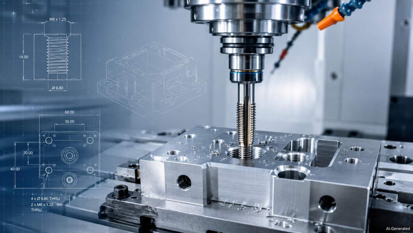
CNC tap cutting internal threads in a metal workpiece
What Is Tapping in Machining?
Tapping is the process of cutting or forming internal threads in a prepared hole using a tap. The hole is typically drilled or otherwise produced to a specified pre-tap diameter before the tap forms the required thread profile. As the tap advances through the hole, its cutting or forming profile produces the thread required for the specified fastener.
Common Applications of Tapped Holes
Tapped holes allow CNC-machined parts to receive screws, bolts, studs, and other threaded fasteners. Tapped holes are widely used in housings, brackets, plates, manifolds, and other machined components where fasteners need to be installed and removed during assembly or service.
CNC Tapping Process
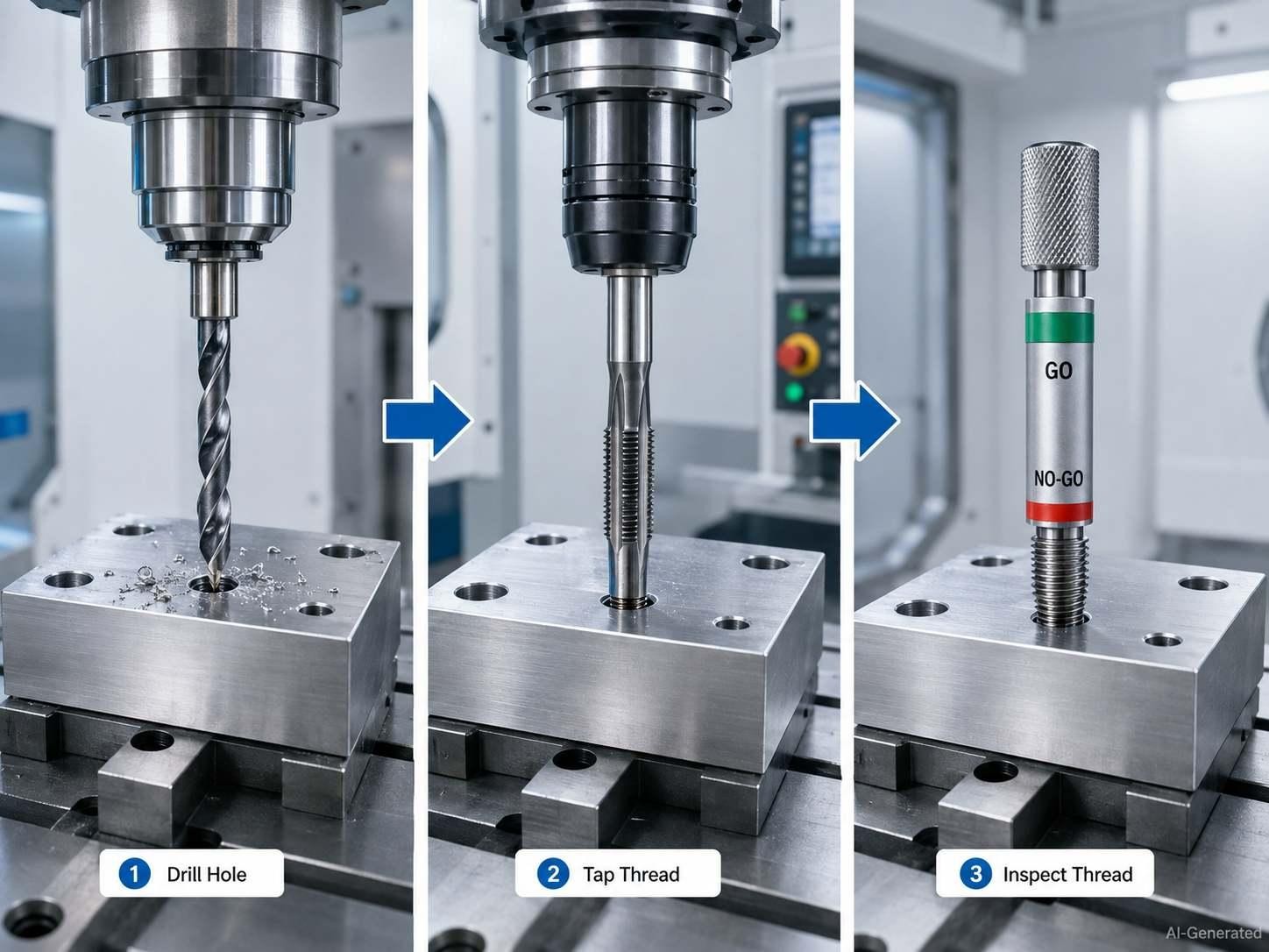
CNC tapping process from drilling to thread inspection
Hole Preparation Before Tapping
Before tapping, the hole must be produced to the specified pre-tap diameter and sufficient depth. Hole size directly affects thread percentage and tapping torque. In a blind hole, the drilled depth must leave room below the usable thread for the tap chamfer and accumulated chips.
CNC Tapping Operation
During CNC tapping, the spindle rotates while the Z-axis advances at a feed rate synchronized with the thread pitch. In rigid tapping, the spindle and feed motion remain synchronized throughout the cutting and reversal cycle, allowing the tap to follow the thread without relying on axial float in the holder.
Thread Inspection and Quality Control
Inspection verifies that the finished thread satisfies drawing requirements. GO and NO-GO thread plug gauges are commonly used to verify whether an internal thread meets its functional acceptance limits. Separate dimensional inspection may be used to verify usable thread depth, pitch diameter, location, or other drawing requirements. Minor-diameter checks may also be required when specified by the drawing or process standard.
CNC Tapping Thread and Material Considerations
Thread Size and Specification Considerations
CNC tapping can produce many common metric and inch thread sizes. But pitch, tolerance class, tap diameter, spindle capability, and available tooling define the range for each machine and part. Metric M threads use a 60 degree symmetrical profile. For general-purpose metric fastening threads, 6H is commonly used for internal threads and 6g for external threads. ASME B1.13M relates this metric system to applications traditionally using inch Class 2A/2B threads, but the tolerance systems are not dimensionally identical.
Material and Geometry Limitations
Material behavior affects tapping torque, chip formation, heat generation, lubrication requirements, and tool life. Aluminum may generate built-up material and burrs, while austenitic stainless steels can increase cutting load and may work-harden if the tap rubs or dwells in the hole.
Types of Taps Used in CNC Machining
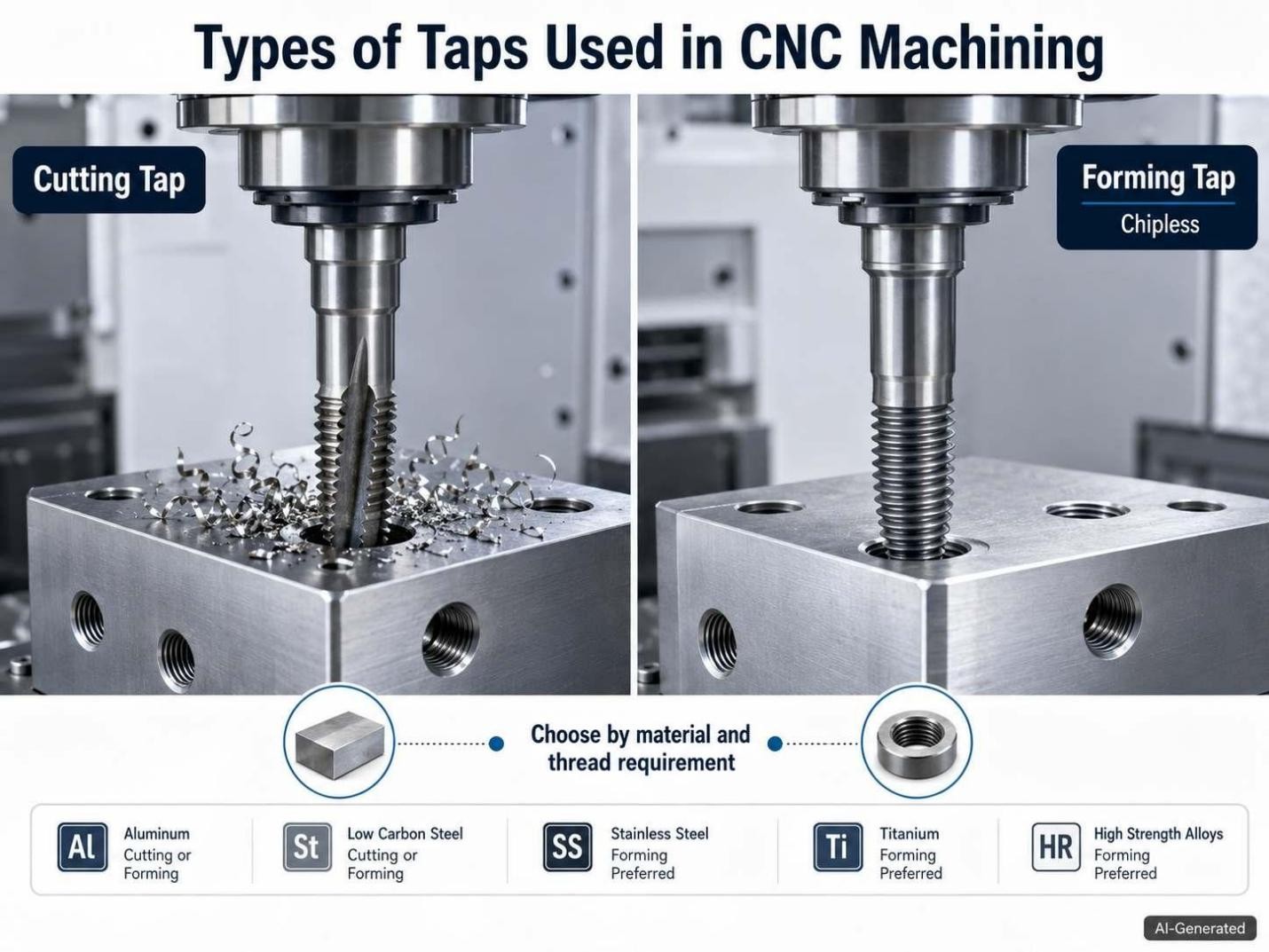
Cutting tap vs forming tap in CNC machining
Cutting Taps
Cutting taps remove stock in order to create the thread profile. They generate chips during tapping machining. Tap geometry is selected according to hole type and chip behavior. Spiral-point taps generally direct chips forward and are commonly used for through holes, while spiral-flute taps pull chips upward and are better suited to blind holes.
Forming Taps
Forming taps create threads by plastically displacing ductile material rather than cutting chips. They therefore require a larger pre-tap hole than a cutting tap for the same nominal thread, and the hole diameter must be controlled closely because it directly affects forming torque and the resulting thread geometry.
Selecting the Right Tap Type
Tap selection should follow the hole geometry and workpiece behavior. For a deeper comparison of spiral-point, spiral-flute, forming, and other tap designs, see JLCCNC's CNC thread tap types guide.
Tapping Different Materials
Tapping Aluminum Parts
Aluminum can produce burrs and chip adhesion. Aluminum can produce built-up material on the cutting edges, particularly when lubrication or tool geometry is poorly matched to the alloy. Tap geometry and chip evacuation should therefore be selected for the specific aluminum grade and hole condition. Edge wear and thread damage may be reduced by using cutting data that is particular to the material.
Tapping Stainless Steel and Harder Alloys
Stainless steel tends to work-harden. Harder steels increase cutting-edge wear and torque during metal tapping. Process stability can be improved by selecting a tap designed for the alloy and following the tool manufacturer's recommended cutting speed, feed, and lubrication conditions. Avoiding rubbing and maintaining consistent feed is especially important with work-hardening stainless steels.
Tapping Plastic Components
Engineering plastics behave differently from metals during tapping because they can soften, expand, or recover elastically under machining load. Use sharp tooling and conservative heat input to avoid distorted or oversized threads.
CNC Tapping Design Considerations
Drill Hole Size Before Tapping
When tapping holes, the pilot diameter should be according to the thread size, pitch, and tap style. Traditional tap-drill charts often target about 75% thread height, but many modern tooling recommendations use approximately 60-70% for non-critical threads to reduce tapping torque and improve tool life. The required value should be based on the thread specification, material, tool manufacturer's recommendation, and functional requirements. Cutting and forming taps may need different pre-hole diameters.
Thread Depth Requirements
Specify usable thread depth according to the fastener, applied load, material strength, and assembly requirements rather than using a universal depth rule. For blind holes, the drilled depth should also account for the tap chamfer and the unthreaded clearance required below the usable thread.
Blind Holes vs Through Holes
Through holes provide an open route for chips. In comparison to this, blind holes confine debris and require tap geometry that is appropriate for evacuating chips away from the bottom. This difference can influence tool selection and attainable thread depth.
Minimum Wall Thickness Around Tapped Holes
A tapped hole needs enough surrounding material to prevent edge breakout or local deformation during machining and service. The required edge distance depends on the thread size and the geometry around the hole, so a single universal value should not be applied to every part. Follow the drawing or applicable design standard when the joint carries significant load.

Precision CNC Machining Service
Designing a part with tapped holes? JLCCNC can review the threaded features from your CAD file and drawing and provide a CNC machining quote before production.
CNC Tapping Speeds and Feeds
Tapping parameters are tied directly to thread pitch. In rigid tapping, spindle speed and axial feed must remain synchronized with the thread geometry. The spindle speed is normally selected from the tap manufacturer's cutting-data recommendation, while the programmed feed is calculated from RPM and thread pitch.
Tapping Speed and RPM
Tapping speed is normally specified as surface speed in SFM or m/min, or directly as a recommended spindle speed for a particular tap. The correct value depends on the tap design and workpiece rather than thread size alone. A high-speed-steel tap and a powder-metal or carbide tap may have very different cutting-speed limits in the same alloy.
For production, start within the tool manufacturer's recommended cutting range. Then judge the process from actual thread inspection and machine load, while watching for abnormal chip formation or accelerated tool wear. Guhring, for example, publishes separate cut-tap data for steel, stainless steel, aluminum alloys, titanium, nickel alloys, and other material groups, with recommendations that also vary by tap grade.
For metric tapping, spindle speed can be estimated from cutting speed with:
RPM = (Cutting Speed x 1000) / (pi x Tap Diameter)
where cutting speed is in m/min and tap diameter is in mm.
For example, an M8 x 1.25 tap running at 500 RPM gives a nominal cutting speed of approximately 12.6 m/min. The 500 RPM value here is only an example for the calculation; the actual production speed should come from the selected tap manufacturer's data.
Tapping Feed Rate
Unlike milling, tapping feed is not normally selected from a generic feed-per-tooth value. For a standard single-start thread, axial feed per spindle revolution corresponds to the thread pitch.
Feed Rate = RPM x Pitch
For an M8 x 1.25 thread at 500 RPM:
Feed Rate = 500 x 1.25 = 625 mm/min
For a 1/4-20 UNC thread, the pitch is 1/20 = 0.05 in/rev. At 1,000 RPM:
Feed Rate = 1,000 x 0.05 = 50 in/min
The control must use the correct pitch for the programmed thread. A feed mismatch during rigid tapping can force the tap to rub, overload, or lose synchronization with the thread.
Setting Tapping Parameters in Production
The programmed RPM is only one part of the process. Hole diameter has a direct effect on thread height and tapping torque, especially when the pre-tap hole is close to the lower end of the specified range. Tool runout and spindle synchronization also matter. In a blind hole, the tap must reach the required usable thread depth without running the chamfer or cutting section into the bottom clearance.
Coolant or tapping lubricant should follow the tap manufacturer's recommendation and the workpiece condition. Stainless steels are particularly sensitive to rubbing because work hardening can occur when the cutting edges stop removing material cleanly. Aluminum may require a different tap geometry and lubrication approach to reduce built-up material on the cutting edges.
For production, verify the first parts rather than changing speed and feed independently. A useful process check is to compare the programmed speed and feed with the actual pre-tap hole size, thread-gauge result, and spindle load. Where tapping torque is available, it provides another useful signal for detecting abnormal cutting conditions.
Final cutting data should always follow the tap manufacturer's recommendation for the specific tool and material. Published values are starting points, not substitutes for verifying the process on the actual machine, workpiece, and hole geometry.
Tapping vs. Thread Milling: Which Process Should You Use?
| Tapping | Thread Milling | |
|---|---|---|
| Tool | Thread-specific tap | Thread mill |
| Material removal | Cuts or forms the thread in one continuous operation | Removes material along a helical toolpath |
| Hole types | Suitable for through and blind holes, depending on tap geometry | Well suited to blind holes and through holes |
| Thread sizes | Generally requires a dedicated tap for each thread specification | One suitable cutter can cover multiple thread diameters within its range |
| Chip evacuation | Can be challenging in blind holes | Generally provides better chip control |
| Tool breakage | A broken tap can be difficult to remove | Lower risk of catastrophic tool breakage |
| Production efficiency | Fast for repeated production of the same thread | More flexible but typically requires additional CNC programming |
| Best suited for | High-volume production and common thread specifications | Difficult materials, large threads, valuable parts, or applications requiring flexibility |
In thread milling vs tapping, tapping drives a thread-specific tool axially through the prepared hole. It is often faster when the same thread specification is produced repeatedly. A suitable thread mill can produce multiple thread diameters within its design range, provided that the required thread profile, pitch, and tool geometry are compatible. Thread milling removes material progressively along a helical toolpath, which can improve chip control and reduce the risk of catastrophic tool breakage compared with a conventional tap. It also allows the thread diameter to be adjusted through the CNC toolpath.
Common CNC Tapping Problems and Solutions
Incorrect Drill Size
A pilot hole that is too small increases tapping torque and breakage risk. As a commonly cited tapping guideline, increasing thread height from about 75% to 100% provides only a small increase in thread strength while requiring substantially more tapping torque. The exact relationship varies with thread geometry, material, and process conditions, so thread percentage should be specified according to the application rather than maximized by default.
Poor Chip Evacuation
Trapped chips can damage thread surfaces or jam the tap inside blind holes. Select flute geometry according to the hole type and material, and maintain adequate lubrication and chip evacuation. Spiral-point taps can push chips forward in through holes, while spiral-flute taps help pull chips out of blind holes.
Incorrect Cutting Parameters
For rigid tapping, the programmed feed must match the thread pitch at the commanded spindle speed. Verify the spindle speed, feed-per-revolution, tapping depth, synchronization, and retract settings before production to reduce the risk of thread distortion, excessive torque, or tool breakage.
Tap Wear or Breakage
Worn cutting edges can raise torque and reduce thread quality. Meanwhile, misalignment, excessive runout, poor workholding, synchronization errors, excessive tapping torque, or unsuitable cutting conditions can all contribute to tap failure. Check tool wear before the tap reaches the end of its expected life, and verify spindle synchronization when breakage occurs repeatedly.
Precision CNC Machining Service
Professional manufacturing, fast turnaround, and quality assurance.
CNC Tapping FAQs
Q: What Size Hole Is Needed Before Tapping?
The required pre-tap diameter depends on the thread size and pitch, tap type, and target thread percentage. For many cutting-tap applications, tooling manufacturers recommend a 60-70% thread target, but the manufacturer's chart should take priority.
Q: How Deep Can a CNC Machine Tap a Hole?
Maximum tapping depth depends on the tap geometry, workpiece material, machine capability, and hole design. In a blind hole, the available clearance below the usable thread becomes especially important because chips and the tap chamfer need room at the bottom.
Q: Can Blind Holes Be Tapped?
Yes. Blind holes can be tapped when the tap geometry and hole depth provide enough room for chip evacuation and the tap chamfer. Spiral-flute taps are commonly used when chips must be pulled away from the bottom of the hole.
Q: When Should Thread Milling Be Used Instead of Tapping?
Thread milling might be worth considering for larger threads, difficult materials, valuable components, or applications whenever reducing tap-breakage risk is critical. It also offers flexibility when one suitable cutter can machine multiple thread diameters.
Conclusion: Tapping in Machining
Reliable tapping starts with a properly prepared hole and a process that keeps the tap synchronized with the thread geometry. For a machined part, the thread specification should suit the material and the way the hole is made. Deep or blind holes may require a different tapping approach.
For parts with tapped holes, JLCCNC can review the threaded features from the CAD file and drawing before production. Upload the files to request a CNC machining quote.
Keep Learning
Laser Engraving Aluminum: Marking Methods & Surface Effects
Key Takeaways Laser engraving usually removes base material to create a recess. Laser marking is a broader term that can describe a surface-color change or material removal, so the process name alone does not define the final result. On aluminum, alloy and surface finish affect marking contrast. A light mark on dark anodized aluminum is a common design target, but the actual appearance depends on the finish and laser process. JLCCNC laser marking produces a recessed area 0.03–0.1 mm deep. The result i......
CNC Cutting Fluid: Types, Functions, Applications, and Selection Guide
Key Takeaways Cutting fluid in machining performs four functions simultaneously: cooling the tool and workpiece, lubricating the tool-chip interface to reduce friction, carrying chips away from the cut zone, and protecting machined surfaces from corrosion between operations. Different machining operations need different fluid priorities: high-speed aluminum milling may need adhesion control and chip evacuation, threading and tapping need strong lubrication, and grinding requires both cooling and fine ......
Blind Hole Machining Guide: What Is a Blind Hole, Types of Holes, and Tapping Tips
What Is a Blind Hole? Types of Holes and CNC Hole Machining Explained In CNC machining, few operations challenge process control and tool stability as much as blind hole machining. A blind hole is a hole that terminates at a defined internal depth rather than breaking through the opposite surface. Because the cavity is enclosed at the bottom, chip evacuation, thermal behavior, tool wear, and dimensional accuracy become far more difficult to manage compared to through-hole machining. These constraints ......
Rake Angle in Machining: Machinists’ Guide to Perfect Cuts
What is Rake Angle? (minaprem) If you've ever stood in front of a CNC machine or a manual lathe, you know that the cutting tool's geometry isn't just some arbitrary design. Every angle, edge, and surface has a job to do, and one of the most important of those is the rake angle. We've been running machines long enough to know that rake angle can make or break your surface finish, tool life, and machining efficiency. In this guide, we're going to walk you through what rake angle is, how it works, and ho......
Sheet Metal vs CNC Machining: A Guide to Choosing the Right Method for Your Metal Parts
Quick Answer: Choose sheet metal for uniform-thickness enclosures, panels, and formed brackets when bends and production volume support lower unit cost. Choose CNC machining for variable wall thickness, precision bores, tight feature relationships, and complex 3D geometry. Use a hybrid design when a formed structure needs precision-machined interfaces. A quote comes back for a bracket, and it's priced as a CNC part — machined from solid aluminum, a few hours of spindle time, a per-part cost that makes......
What Steps Are Taken To Minimize Waste In CNC Machining Processes?
How to Reduce Waste in CNC Machining: 5 Practical Strategies Quick Answer: CNC machining waste is reduced mainly through DFM, near-net stock, efficient toolpaths, preventive tool maintenance, and alloy-segregated recycling. The biggest gains usually come before cutting: reduce unnecessary material removal and prevent scrap or rework. Every CNC-machined part starts as more material than it ends up being. A pocket gets milled out, a profile gets cut away, a boss gets faced down to size — and all of that......