Tapped Hole vs Threaded Hole: Differences, Machining Methods & Design Guide
15 min
- Introduction
- What Is a Tapped Hole
- What Is a Threaded Hole
- How Threaded Holes Are Machined
- Threaded Hole Callouts and Specifications
- Designing Threaded Holes for CNC Machining
- Common Threaded Hole Machining Problems and Solutions
- Tapped Hole vs Threaded Hole FAQs
Key Takeaways
- A tapped hole is a threaded hole produced with a tap; “threaded hole” is the broader term covering internal threads made by tapping, thread milling, or thread forming.
- Internal threads are produced by tapping, thread milling, or thread forming, chosen based on material, thread size, hole geometry, and production requirements.
- A threaded-hole callout should specify thread size, pitch, standard, tolerance class, and usable depth.
- Thread size, depth, wall thickness, and tool accessibility should be planned before machining to avoid rework and assembly problems.
A tapped hole is a type of threaded hole. “Tapped” describes how the internal thread is produced, while “threaded” describes the finished internal-thread feature.
| Feature | Tapped Hole | Threaded Hole |
|---|---|---|
| Meaning | Internal thread made with a tap | General term for any internally threaded hole |
| Possible production methods | Tapping | Tapping, thread milling, forming |
| Typical use | Bolts, screws, threaded fasteners | Any component requiring an internal thread |
| CNC programming | Tap cycle commonly used | Method depends on thread type and production needs |
Introduction
Internal threads are common on CNC-machined housings, brackets, plates, shafts, covers, and assemblies. A drawing might specify M6 × 1.0 for an internal thread. A drawing may instead specify the feature simply as a threaded hole. For engineers and buyers, the important point is the thread requirement shown on the drawing. Thread size, pitch, tolerance class, usable thread depth, and whether the hole is blind or through all affect how the feature is manufactured and inspected.
This article covers:
- The difference between tapped and threaded holes
- The common CNC methods used to produce them
- The design details that can prevent problems during machining and assembly.
What Is a Tapped Hole
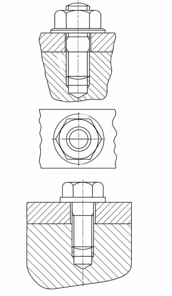
Tapped hole - ScienceDirect
A tapped hole is a hole with internal threads produced using a tap. A cutting tap removes material to form the thread, while a forming tap creates the thread by displacing material. The tap follows the axis of the prepared hole and forms the internal thread. This allows a mating fastener to engage directly with the part.
A tapped hole is a threaded hole produced using a tap, while a threaded hole is the broader term for any hole containing an internal thread. Therefore, every tapped hole is a threaded hole, but not every threaded hole is produced by tapping.
How a Tapped Hole Is Created
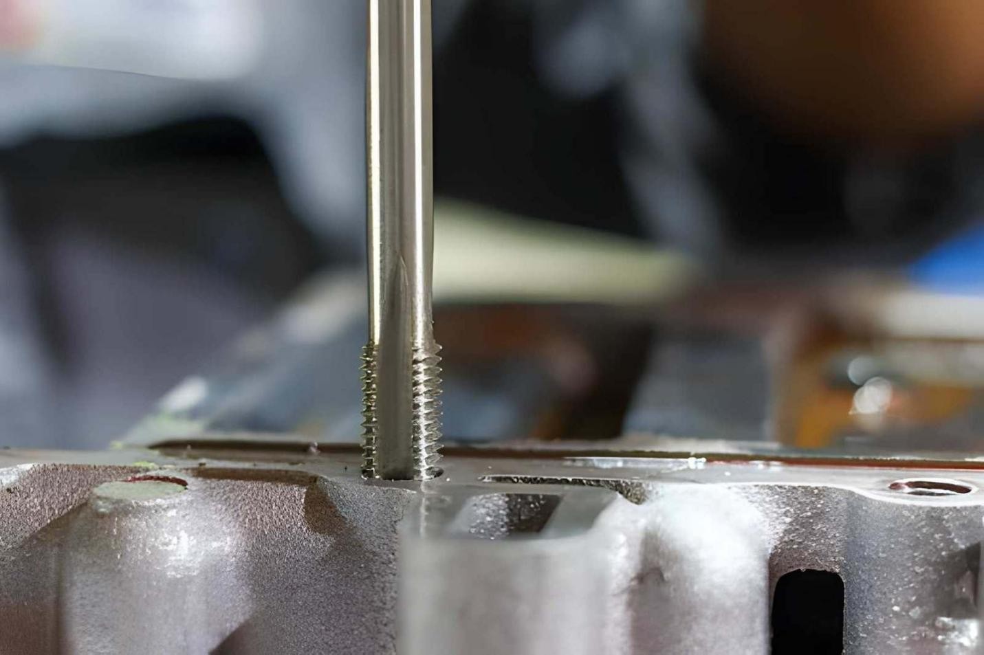
Screw hand tap cutting tool (iStock)
The process normally starts by drilling the hole to the required tap-drill diameter. The tap is aligned with the hole axis and driven into the prepared hole to form the internal thread.
For a CNC-machined part, the basic sequence involves:
- Drill the hole to the specified tap-drill size.
- Prepare the hole entrance with a chamfer when required.
- Apply a suitable cutting fluid for the material and tap.
- Run the tapping operation to the specified thread depth.
- Remove the tap and clean the hole.
- Check the finished thread with the appropriate gauge.
The tap-drill size depends on the thread diameter, pitch, thread form, and required percentage of thread. It should therefore be taken from the applicable thread standard and tooling data rather than estimated from the nominal thread diameter.
For a blind hole, the available depth also needs to account for the drill point and incomplete thread at the bottom. The specified thread depth should not be confused with the total drilled-hole depth.
Common Applications of Tapped Holes
Tapped holes are commonly preferred when a fastener needs to screw directly into the machined component without a separate nut.
Typical CNC-machined applications include:
- Aluminum housings for covers and brackets
- Fixture plates for mounting and positioning
- Motor and gearbox housings for covers and accessories
- Manifolds and blocks requiring threaded ports
The thread specification should define the required thread size, pitch, tolerance class where applicable, and usable thread depth so the manufacturer can select an appropriate production method.
What Is a Threaded Hole
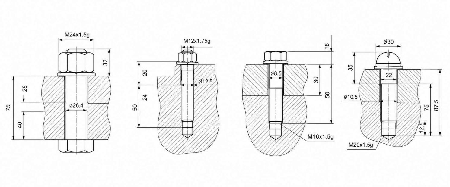
Threading hole technical diagram - Shutterstock
A threaded hole is an internal hole containing a helical thread that allows a screw, bolt, stud, or other threaded component to engage with the part. The term describes the finished feature, not one specific machining method.
Internal threads can be produced by several processes. Tapping is one of the most common methods; however, thread milling and thread forming can also produce threaded holes.
The production method depends on factors such as material, thread size, hole geometry, and production requirements.
How Threaded Holes Are Machined
Internal threads can be produced by tapping, thread milling, or thread forming. Selection depends on the material, thread size, hole depth, part geometry, production volume, and required thread condition.
Tapping for Internal Threads
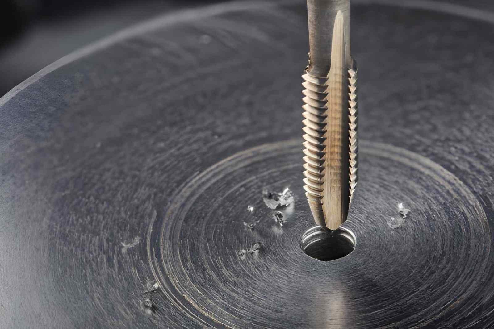
Thread tap drill steel billet (iStock)
Tapping is the most common method for producing internal threads in CNC-machined parts. A tap has cutting edges that follow the prepared hole and remove material to create the thread profile.
Tapping is widely used for standard internal threads across a broad range of thread sizes and suitable materials. CNC machines can use rigid tapping cycles to keep spindle rotation and feed synchronized with the thread pitch.
For blind holes, the available depth must account for the drill point, tap entry, incomplete threads, and required usable thread depth.
Thread Milling for Complex Thread Features
Thread milling uses a rotating cutter that moves along a helical toolpath to generate the internal thread. Unlike a tap, the cutter does not have to match the complete hole diameter.
Thread milling is useful for large internal threads, difficult-to-machine materials, interrupted holes, or applications where thread position and machining flexibility are important.
Thread milling can be especially useful for blind holes because the cutter can enter and leave the thread without requiring a long tap to travel through the entire feature. Depending on the cutter and toolpath, one thread mill can also produce different thread diameters, which can reduce tooling requirements for certain production runs.
Thread Forming for Suitable Materials
Thread forming creates the internal thread by displacing the material instead of cutting it away. The forming tap pushes the material into the thread profile.
This method is suited to ductile materials that can withstand the forming pressure. Aluminum and selected steel grades can be suitable for thread forming, provided the material has sufficient ductility and the hole size and tooling conditions meet the manufacturer's recommendations.
Because no chips are produced during the forming operation, it can be useful for production machining. The starting hole size is different from a cutting-tap hole and must follow the tooling manufacturer's specification.
Choosing the Right Threading Method
For a standard thread in a machinable material, tapping is usually the simplest option. For CNC machining, the choice between tapping and thread milling depends on thread size, material, hole geometry, production volume, and machine capability.
| Method | Typical use | Main consideration |
|---|---|---|
| Tapping | Standard internal threads | Efficient for common thread sizes |
| Thread milling | Large, difficult, or interrupted threads | Requires suitable toolpath and machine control |
| Thread forming | Ductile materials suitable for cold forming | Requires correct hole size and forming conditions |
The drawing should define the thread size, pitch, standard, tolerance class, and usable depth. The manufacturer can then select the appropriate threading method based on the actual part, CNC capabilities, and production requirements.
Threaded Hole Callouts and Specifications
A threaded-hole callout tells the machinist what thread to make and how deep it needs to be. A thread callout should provide the information needed to define the required internal thread, including the thread size, pitch, tolerance where applicable, and usable depth.
Thread Size and Pitch
Thread size identifies the nominal thread diameter. Pitch defines the distance between adjacent thread crests.
For example:
- M6 × 1.0 - 6 mm nominal diameter with a 1.0 mm pitch
- M10 × 1.5 - 10 mm nominal diameter with a 1.5 mm pitch
- 1/4-20 UNC - 1/4 inch nominal diameter with 20 threads per inch
For metric threads, pitch is normally given directly in millimetres. For inch threads, TPI (threads per inch) is used.
Thread Depth and Hole Depth
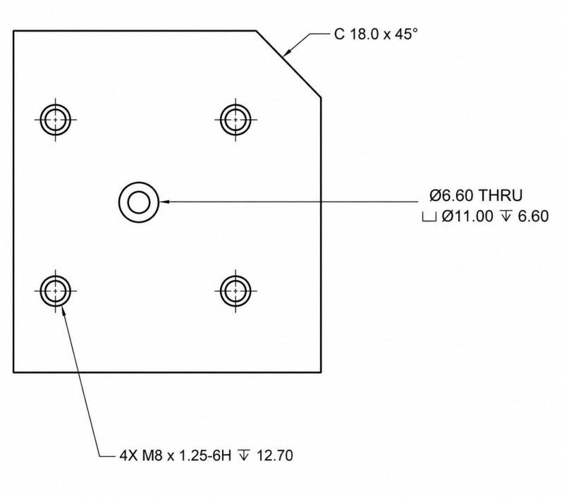
Threaded hole callout (Siemens Community)
The specified thread depth tells the machinist how much usable thread is required. It is different from the total drilled depth of a blind hole.
For example:
M8 × 1.25 - 12 DEEP
In this example, the 12 mm dimension indicates the required usable thread depth.
The drilled hole normally needs to be deeper than the usable thread because space is required for the drill point and the incomplete thread at the bottom.
For a through hole, the drawing may indicate the thread as THRU when the internal thread extends through the part.
Thread Class and Tolerance
The thread tolerance designation defines the allowable limits of the internal thread and its fit with the mating external thread.
For metric threads, a drawing may specify an internal thread such as:
M8 × 1.25 - 6H
For inch threads, an internal thread may use a class such as:
1/4-20 UNC-2B
The required class should come from the design requirement and the applicable thread standard. A general-purpose fastening thread does not need the same specification as a precision-threaded connection.
Thread Callout Examples
Common drawing formats include:
Metric blind hole:
4X M6 × 1.0 - 10 DEEP
Four holes require an M6 × 1.0 thread with 10 mm of usable thread depth.
Metric through hole:
M10 × 1.5 THRU
The M10 × 1.5 internal thread continues through the component.
Metric thread with tolerance class:
M8 × 1.25 - 6H
The callout specifies the nominal size, pitch, and internal-thread tolerance class.
Inch thread:
1/4-20 UNC-2B
This specifies a 1/4-inch UNC internal thread with 20 TPI and a 2B internal-thread class.

Precision CNC Machining Service
Have a threaded part ready for production? Upload your CAD model and 2D drawing for an engineering review.
Designing Threaded Holes for CNC Machining
Threaded holes should be sized around the fastener, joint load, part geometry, and material. These decisions are best made before machining because changing the hole after the part is produced can affect surrounding features.
Select Appropriate Thread Size
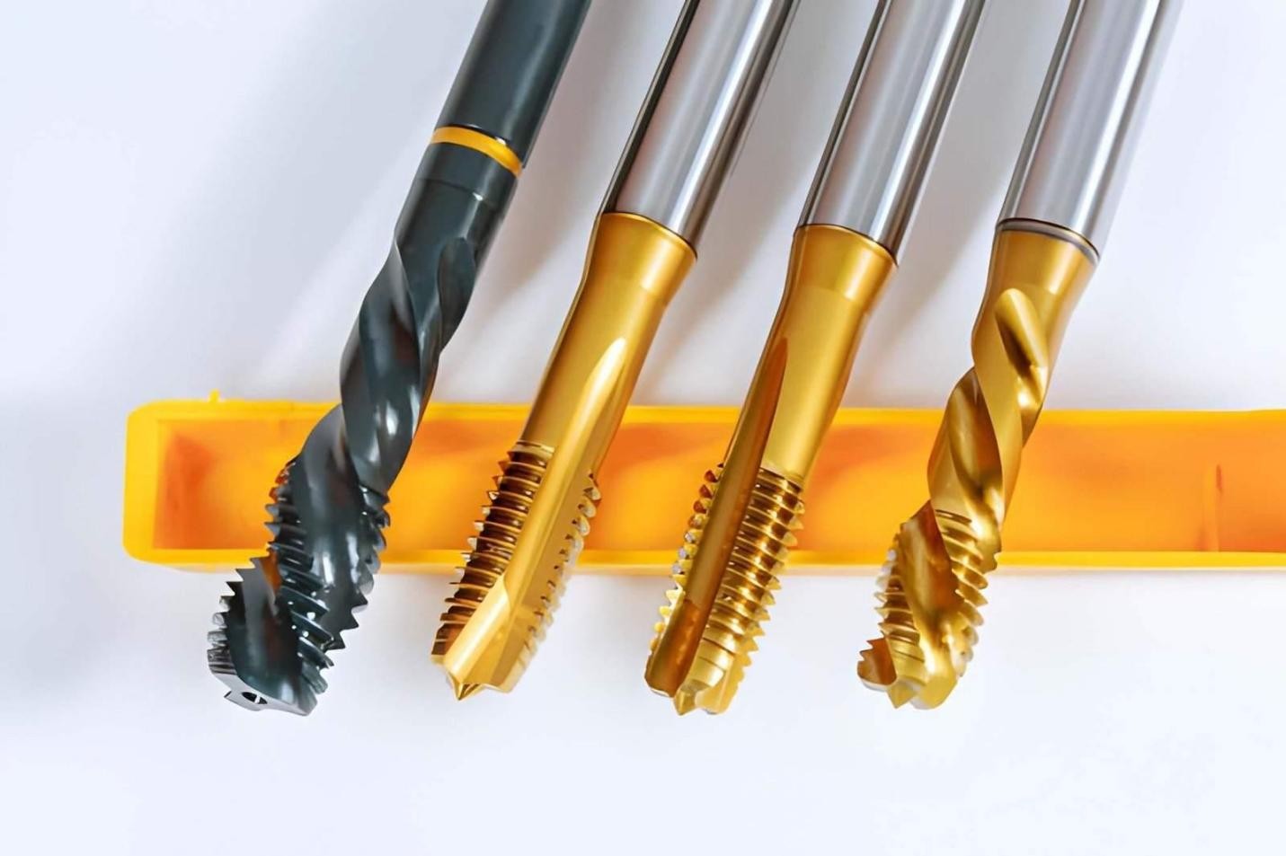
Set of taps for threading in metal (iStock)
Choose the thread size from the fastener size and the load carried by the joint.
Check the available space around the hole before selecting a larger thread.
For example, an M6 fastener may suit a small cover or bracket, while a larger joint may require M8, M10, or a larger thread.
The thread size should also leave enough material around the hole for the part to carry the applied load.
Determine Proper Thread Depth
The required engagement depends on the material and joint load. Aluminum alloys may require greater thread engagement than steel in some joint designs to achieve the required thread strength.
For a blind hole, specify the usable thread depth separately from the total hole depth.
Maintain Sufficient Wall Thickness Around Threaded Holes
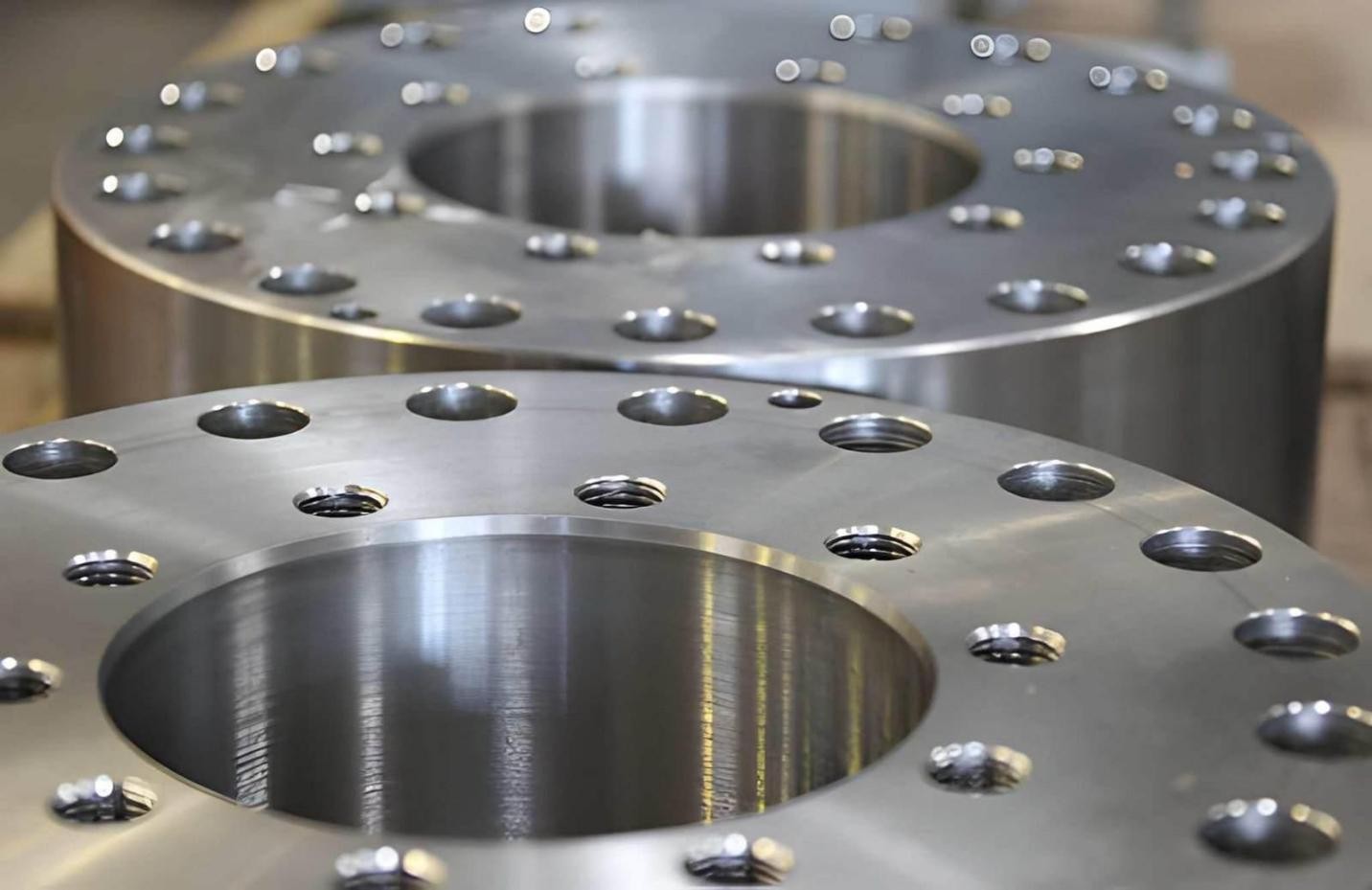
Large machined parts with threaded holes (iStock)
Leave enough material between the threaded hole and nearby edges, pockets, slots, and other holes. A hole placed too close to an edge reduces the remaining section and can weaken the part. Check the minimum wall around the complete thread profile, not just the center-to-edge distance shown on the engineering drawing.
Consider Hole Location and Tool Accessibility
Place threaded holes so the tap or thread mill can approach the hole along its axis. Check nearby walls, bosses, pockets, clamps, and adjacent features before fixing the hole location. A hole may fit the assembly layout but still be difficult to access with the required tooling.
Match Thread Requirements With Material Properties
Thread design should suit the material's strength and ductility. Compared with many aluminum alloys, steels generally provide greater internal thread strength, although the actual performance depends on the specific material and thread design.
For aluminum parts that will be assembled and disassembled frequently, a thread insert may be preferable to relying on the machined aluminum thread alone.
For materials suitable for thread forming, also check the manufacturer's recommended forming-tap conditions and hole size before selecting that process.
Manufacturing Note
For CNC-machined parts, the drawing should define the required thread rather than relying on a generic “threaded hole” description. Unless the thread-production method is itself a design requirement, the manufacturer can generally select tapping, thread milling, or forming based on the part and process requirements.
Common Threaded Hole Machining Problems and Solutions
When troubleshooting a thread problem, check the hole, tooling, machine position, and drawing requirements in that order.
Incorrect Tap Drill Size
The tap-drill diameter determines how much material the cutting tap must remove to form the thread.
- Hole too small: tapping load increases, and the tap can break.
- Hole too large: the finished thread has less thread engagement.
- Wrong drill size: the thread may fail the required gauge even though the nominal thread size is correct.
Use the recommended tap-drill size for the specific thread and material. Measure the drilled hole before starting the tapping operation when the feature is critical.
Poor Thread Formation
If the tap cuts unevenly, inspect the tap condition, spindle speed, feed rate, lubrication, and chip evacuation.
For example, if an M8 × 1.25 thread is being tapped, the feed must correspond to the 1.25 mm pitch during rigid tapping. Incorrect synchronization can damage the thread.
Check the finished thread with the specified GO/NO-GO gauge rather than judging it only by visual appearance.
Damaged or Incomplete Threads
Inspect the thread entrance and the bottom of the blind hole for incomplete or damaged threads.
Common causes include:
- Worn tap
- Chips packed inside a blind hole
- Insufficient hole depth
- Misalignment between the tap and the hole axis
- Excessive tapping load
Replace a worn tap and clear chips from the hole before continuing the operation. For blind holes, make sure the usable thread ends above the bottom of the drilled hole.
Thread Positioning Errors
The thread can have the correct size and still be in the wrong location. Check the hole position from the drawing datums using the appropriate inspection method. For a pattern of threaded holes, verify the hole-to-hole location and the pattern relative to the primary datum.
If several holes show the same positional shift, check the work offset and CNC coordinates before changing the tooling.
Incorrect Thread Specification
A thread can be machined correctly but still be wrong for the assembly if the drawing specification was misunderstood.
Check all of the following before programming:
Thread size → pitch → standard → class → usable depth → through/blind condition
For example, M8 × 1.25 and M8 × 1.0 cannot be substituted for each other. If the drawing does not identify the required thread standard or tolerance class, confirm the requirement before machining.
Tapped Hole vs Threaded Hole FAQs
Q: Is a tapped hole the same as a threaded hole?
A tapped hole is a threaded hole made with a tap. “Threaded hole” is the broader term because internal threads can also be produced by thread milling and thread forming.
Q: Can threaded holes be made without tapping?
Internal threads can be produced without a cutting tap. Thread milling removes material with a milling cutter, while thread forming displaces material to create the thread. The choice is influenced by the material, thread specification, hole geometry, and production requirements.
Q: Can CNC machines create threaded holes?
CNC machines commonly produce threaded holes using rigid tapping, thread milling, and thread forming. The machine needs suitable spindle control, tooling, programming, and workholding for the selected method.
Q: What is the difference between a tapped hole and a threaded insert?
A tapped hole has its thread directly in the parent material. A threaded insert is a separate component installed into a prepared hole to provide an internal thread.
In softer materials such as aluminum, an insert can provide a more durable thread for assemblies that are frequently removed and installed.
Q: What is a threaded hole callout?
A threaded-hole callout defines the required thread on an engineering drawing. It commonly includes the nominal diameter, pitch, thread standard, tolerance class, and usable depth.
For example:
M8 × 1.25 - 6H, 12 DEEP
This specifies an 8 mm metric thread with a 1.25 mm pitch, 6H internal-thread class, and 12 mm usable thread depth.
Q: What size hole is needed for threading?
The hole size needed for threading depends on the thread specification and whether the thread is cut or formed. For a cut thread, the starting hole is normally selected using the recommended tap-drill size for the specified thread.
Precision CNC Machining Service
Professional manufacturing, fast turnaround, and quality assurance.
Conclusion About Tapped Holes and Threaded Holes
A tapped hole is a type of threaded hole. “Tapped” refers to the method used to produce the internal thread, while “threaded hole” refers to the finished internal-thread feature regardless of how it was produced.
For CNC parts, the production method is selected according to the part and thread requirements. Tapping is common for standard threads, while thread milling or forming may be more appropriate for specific materials or geometries.
Before machining, the drawing should clearly define the required thread and its usable depth. Where applicable, the thread standard and tolerance class should also be specified.
If you have a threaded part ready for production, upload your CAD model and 2D drawing to JLCCNC for an engineering review. The drawing can be checked for thread requirements and manufacturability before machining, helping identify potential issues early.
JLCCNC can then provide DFM feedback and a quotation based on the actual part requirements, with the machining approach confirmed before production.
Keep Learning
Laser Engraving Aluminum: Marking Methods & Surface Effects
Key Takeaways Laser engraving usually removes base material to create a recess. Laser marking is a broader term that can describe a surface-color change or material removal, so the process name alone does not define the final result. On aluminum, alloy and surface finish affect marking contrast. A light mark on dark anodized aluminum is a common design target, but the actual appearance depends on the finish and laser process. JLCCNC laser marking produces a recessed area 0.03–0.1 mm deep. The result i......
CNC Cutting Fluid: Types, Functions, Applications, and Selection Guide
Key Takeaways Cutting fluid in machining performs four functions simultaneously: cooling the tool and workpiece, lubricating the tool-chip interface to reduce friction, carrying chips away from the cut zone, and protecting machined surfaces from corrosion between operations. Different machining operations need different fluid priorities: high-speed aluminum milling may need adhesion control and chip evacuation, threading and tapping need strong lubrication, and grinding requires both cooling and fine ......
Blind Hole Machining Guide: What Is a Blind Hole, Types of Holes, and Tapping Tips
What Is a Blind Hole? Types of Holes and CNC Hole Machining Explained In CNC machining, few operations challenge process control and tool stability as much as blind hole machining. A blind hole is a hole that terminates at a defined internal depth rather than breaking through the opposite surface. Because the cavity is enclosed at the bottom, chip evacuation, thermal behavior, tool wear, and dimensional accuracy become far more difficult to manage compared to through-hole machining. These constraints ......
Rake Angle in Machining: Machinists’ Guide to Perfect Cuts
What is Rake Angle? (minaprem) If you've ever stood in front of a CNC machine or a manual lathe, you know that the cutting tool's geometry isn't just some arbitrary design. Every angle, edge, and surface has a job to do, and one of the most important of those is the rake angle. We've been running machines long enough to know that rake angle can make or break your surface finish, tool life, and machining efficiency. In this guide, we're going to walk you through what rake angle is, how it works, and ho......
Sheet Metal vs CNC Machining: A Guide to Choosing the Right Method for Your Metal Parts
Quick Answer: Choose sheet metal for uniform-thickness enclosures, panels, and formed brackets when bends and production volume support lower unit cost. Choose CNC machining for variable wall thickness, precision bores, tight feature relationships, and complex 3D geometry. Use a hybrid design when a formed structure needs precision-machined interfaces. A quote comes back for a bracket, and it's priced as a CNC part — machined from solid aluminum, a few hours of spindle time, a per-part cost that makes......
What Steps Are Taken To Minimize Waste In CNC Machining Processes?
How to Reduce Waste in CNC Machining: 5 Practical Strategies Quick Answer: CNC machining waste is reduced mainly through DFM, near-net stock, efficient toolpaths, preventive tool maintenance, and alloy-segregated recycling. The biggest gains usually come before cutting: reduce unnecessary material removal and prevent scrap or rework. Every CNC-machined part starts as more material than it ends up being. A pocket gets milled out, a profile gets cut away, a boss gets faced down to size — and all of that......