Flange Machining: CNC Process and Custom Manufacturing Guide
12 min
- What Is Flange Machining?
- What Types of Flange Features Can Be CNC Machined?
- Materials for CNC Flange Machining
- Flange Machining Process
- Key Machining Considerations for Flanges
- Custom Flange Manufacturing
- Flange Design Considerations for CNC Machining
- Flange Machining Inspection and Quality Control
- What Information Is Needed for a Custom Flange RFQ?
- Flange Machining FAQs
- Flange Machining Conclusion
Key Takeaways
- Flange machining can create faces, bores, grooves, holes, threads, hubs, and steps.
- Material affects machinability, corrosion resistance, weight, and mechanical performance.
- Datum relationships and flange geometry can influence sealing, alignment, and assembly.
- Custom production supports non-standard interfaces, prototypes, and low-volume orders.
- Inspection verifies dimensions, geometry, surface condition, and drawing requirements.
- An RFQ should include design files, mating information, quantity, and functional needs.
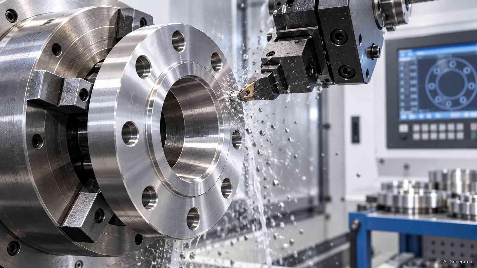
CNC machining a precision metal flange
Flanges may look straightforward, but their performance depends on related features working together. Where a flange forms a gasketed joint, the facing geometry and surface condition must support the specified seal. Where it serves as a mounting or adapter interface, the bore, bolt pattern, and locating surfaces must establish the required alignment and load path. Flange machining uses CNC equipment to produce these features from engineering drawings or CAD models to meet application-specific geometry and tolerance requirements. This guide covers machinable features, materials, production stages, design considerations, inspection, custom manufacturing, and RFQ requirements.
What Is Flange Machining?
Flange machining is the CNC machining of a flange or flange blank to produce the required faces, bores, bolt patterns, grooves, threads, and other mating features to the dimensions and tolerances defined by the drawing or applicable standard. Standard features might include sealing lands, center openings, bolt circles, recesses, shoulders, and threaded connections that allow the flange to join, locate, or seal mating components.
Machined Flanges vs. Standard Flanges
A machined flange is made to defined dimensions through machining. An off-the-shelf standard flange follows established dimensional and rating conventions for common applications. These terms are not opposites. A standard flange may also be machined. Custom machined versions can depart from catalogue dimensions to match a component or interface. For applicable pipe flanges and flanged fittings, ASME B16.5-2025 covers pressure-temperature ratings, materials, dimensions, tolerances, marking, testing, and related requirements for NPS 1/2 through NPS 24. A custom part should be described as compliant with that standard only when its specified type, size, pressure class, material, facing, dimensions, marking, and applicable testing requirements have been confirmed. A non-standard machined interface should not be assumed to inherit an ASME pressure rating merely because it resembles a standard flange.
What Types of Flange Features Can Be CNC Machined?
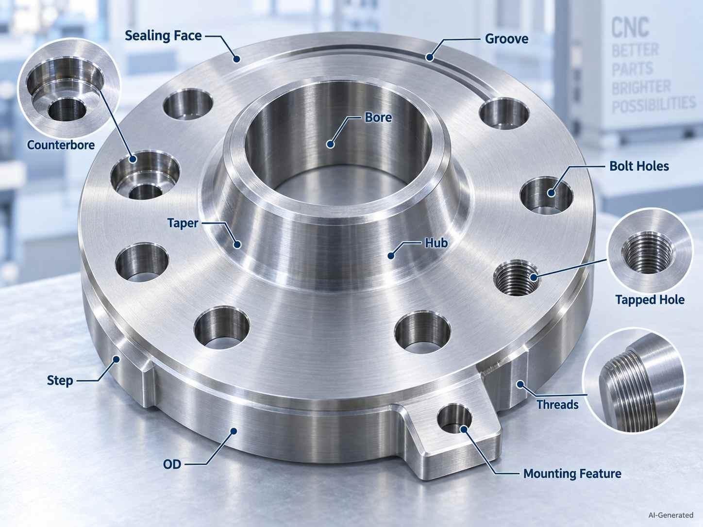
CNC machined flange features and geometry
Sealing Faces and Grooves
CNC machining can produce flat or raised sealing faces, concentric recesses, annular grooves, and other sealing features specified by the flange design. Wider open surfaces allow easier cutter access. Narrow or deep grooves may require longer-reach tooling, which can reduce tool rigidity and increase the risk of deflection or poor chip evacuation.
Internal Bores, Tapers, and Threads
Tapers, threads, straight bores, and stepped bores are all examples of possible internal geometry configurations. When the depth is greater, the diameter is narrower, or there is a sudden transition inside the structure, it might limit tool access and raise the requirement for reach.
Bolt Hole Patterns, Counterbores, and Tapped Holes
Bolt circles may combine through-holes, counterbores, spotfaces, or tapped holes. Hole count, diameter, spacing, and depth affect tool selection and how each location can be machined.
Outside Diameters, Hubs, Steps, and Mounting Features
Around the exterior, CNC flange geometry may include outside diameters, hubs, shoulders, steps, flats, and mounting bosses. Large diameter changes or closely spaced features may require additional tool access, different tooling, or another machining setup.
Materials for CNC Flange Machining
Stainless Steel and Carbon Steel
Stainless steels are commonly selected where corrosion resistance is important, while carbon and alloy steels may be used where strength, temperature capability, pressure service, and cost need to be balanced. The material grade and supply condition also affect cutting behavior and machining stability. Stainless alloys can require more controlled cutting conditions than many carbon steels.
Aluminum for Lightweight Mounting and Adapter Flanges
Aluminum is attractive for mounting and adapter flanges wherever low weight, corrosion resistance, and good machinability are important. Its alloy composition affects strength, workability, and service performance. Engineers can balance mass against operating demands.
Specialty Metals and Engineering Plastics
Other materials, including titanium and engineering plastics, may be used for specialized flange applications where weight, corrosion resistance, electrical properties, or load requirements dictate the material choice. Tooling, cutting conditions, dimensional stability, and finishing requirements can vary significantly with material, so the material specification should be established early in the flange machining process.
Flange Machining Process
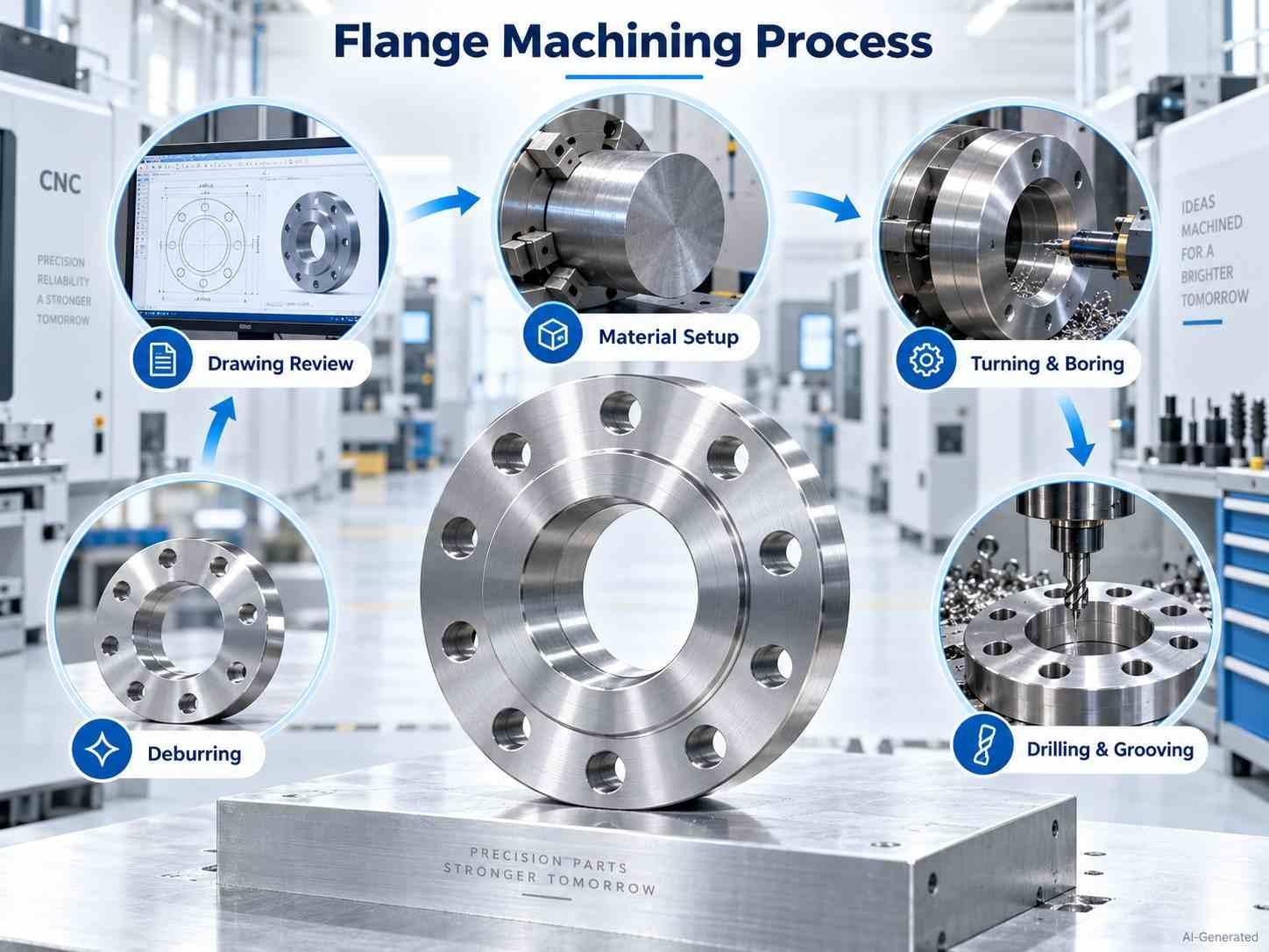
CNC flange machining process from drawing to deburring
Drawing Review and Machining Planning
The workflow begins with the drawing or CAD model. That is where machinists assess geometry, feature relationships, stock form, and production quantity. For a custom flange, these inputs guide operation order, machine choice, tool access, and setup count.
Material Preparation and Workholding
Stock is prepared with machining allowance. Workholding provides support for the component without obstructing the necessary surfaces. Diameter, thickness, material behavior, and batch size can change the chuck, fixture, or setup approach.
CNC Turning, Facing, and Boring
Rotational features are commonly produced by CNC turning, including the outside diameter, hubs, shoulders, and stepped profiles. Facing establishes the required flange surfaces, while boring produces or finishes internal diameters. The part geometry and required tolerances determine whether these features can be completed in one setup or require additional operations.
Drilling, Threading, and Grooving
Bolt holes, threads, grooves, and recesses are machined according to the selected setup sequence. The order depends on datum strategy, workholding, feature access, machine configuration, and the tolerances that must be maintained between related features.
Deburring and Final Finishing
After primary machining, burrs are removed from machined edges and holes. Any specified surface treatment, marking, or secondary finishing is then completed before final inspection and release.
Key Machining Considerations for Flanges
Bore, Flange Face, and Datum Relationships
The drawing should define how the bore, flange face, and bolt pattern relate to the designated datums. These relationships determine how the flange is located, oriented, inspected, and assembled. For critical interfaces, controlling the relationship between features is often more important than simply tightening the size tolerance of each feature independently.
Bolt Hole Patterns and Positional Accuracy
Bolt-hole diameter, spacing, and location around the bolt circle affect whether or not mating hardware passes through correctly and distributes clamping load as intended. Bolt-hole positional error can make assembly difficult, prevent fasteners from passing freely through the mating parts, or force the joint into an unintended condition during assembly.
Flange Face Flatness and Surface Finish
The sealing face must meet the specified flatness and surface-texture requirements for the selected gasket and joint design. For a standardized gasketed pipe joint, specify the flange facing type and any required facing finish or serration pattern together with the applicable standard. Do not select a surface-roughness value independently of the gasket and joint design. For a custom seal, define the mating seal type, contact geometry, required flatness, surface texture, and acceptance method on the drawing.
Face-to-Bore Perpendicularity and Alignment
Perpendicularity controls the orientation of the flange face relative to a datum axis, such as a bore axis. Excessive deviation can cause the mating component to sit at an unintended angle, which may affect assembly alignment or joint seating. Where this relationship is functionally important, the drawing should define the datum structure and geometric tolerance rather than relying only on general dimensional tolerances.

Precision CNC Machining Service
Have a flange drawing ready for machining? JLCCNC can review the design for manufacturability and provide a project-specific quote. Upload your CAD files to get an instant CNC machining quote and DFM feedback from JLCCNC engineers.
Custom Flange Manufacturing
When Custom Flanges Are Required
Custom flanges are useful when a standard catalogue configuration cannot match a project-defined interface, legacy assembly, restricted installation space, or unusual functional geometry. CNC machining allows the flange to be produced to the dimensions and feature relationships required by the application.
Manufacturing from Drawings and CAD Models
Once the need is established, an engineering drawing or 3D CAD model provides the manufacturing definition. CNC production can use this digital geometry to create non-standard dimensions and mating interfaces that correspond with the intended assembly.
Prototype and Low-Volume Production
CNC machining is well suited to prototype and low-volume flange production because it does not require dedicated hard tooling in the way many high-volume forming processes do.
Flange Design Considerations for CNC Machining
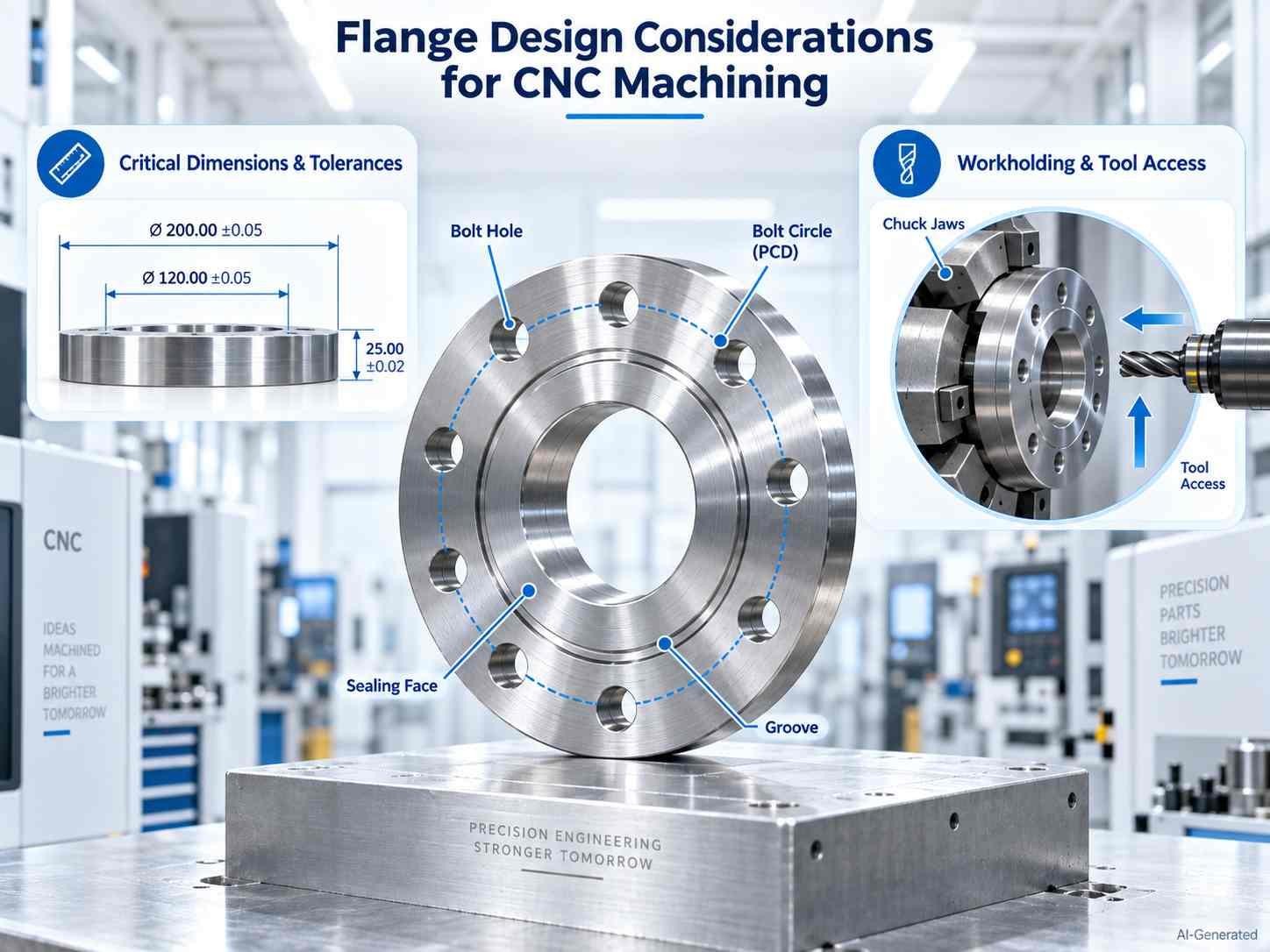
CNC flange design dimensions, bolt pattern, and tool access
Define Critical Dimensions and Tolerances
Before flange machining begins, the drawing should identify overall diameter, bore size, thickness, hub dimensions, datum references, and tolerances for sealing or mating geometry. This keeps manufacturing intent unambiguous and avoids unwanted precision on noncritical features.
Specify Bolt Patterns and Sealing Features
Define bolt-circle diameter, hole count, hole size, angular spacing, counterbores, tapped locations, sealing-face geometry, and required surface texture. These details govern how the flange joins its mating component as well as how the joint seals.
Consider Workholding and Tool Access
Leave enough accessible geometry around the outside diameter, hub, rear face, and recesses for secure workholding and cutter reach. Deep pockets, narrow shoulders, or features crowded near a chucking area can restrict access and raise setup difficulty.
Thin Flanges and Machining Distortion
Thin flanges can be more sensitive to workholding pressure, cutting forces, and residual stress than thicker sections. Clamping force that is acceptable for a rigid part may distort a thin flange and affect its final flatness after the part is released. For critical sealing faces, the machining sequence and support strategy should therefore be considered together with the drawing tolerances rather than treating flatness as an isolated dimension.
Flange Machining Inspection and Quality Control
Dimensional and Geometric Inspection
For critical flange interfaces, inspection may include bore measurement, flange-face flatness or perpendicularity checks, bolt-hole pattern verification, and surface roughness measurement. CMM inspection can be used when the drawing requires datum-based verification of feature location or geometric relationships between the bore, flange face, and bolt pattern.
Surface Finish and Sealing Face Inspection
Surface verification checks the specified surface roughness, lay, and other surface conditions of the sealing area. Where flatness is functionally critical, inspection should also verify the face against the drawing-defined geometric requirement rather than treating surface roughness as a substitute for flatness.
Drawing and Specification Verification
Quality control after flange machining compares the completed part with drawing notes, tolerances, referenced specifications, and other stated acceptance requirements. This review confirms that the delivered flange matches the engineering definition as a whole.
What Information Is Needed for a Custom Flange RFQ?
Required Design Files
Start the RFQ with a dimensioned engineering drawing and, wherever available, a 3D CAD model such as STEP. Include the drawing revision, material grade, tolerances, surface requirements, and any referenced standards or specifications so the manufacturer can quote against the correct design definition.
Functional and Mating Information
Describe the mating component, sealing method, operating environment, and any interface conditions that affect the flange. For a pressure-retaining or vacuum-sealing joint, also state the service medium, design pressure and temperature, applicable standard or pressure class, facing type, gasket type, bolting requirements, and any leak, pressure, or hydrostatic test requirements. This context allows the manufacturer to identify functionally critical characteristics instead of considering every dimension equally.
Production Requirements
State the order quantity, prototype or production status, requested material, finishing needs, documentation needs, and delivery expectations. These details allow the supplier to prepare an RFQ response around the intended manufacturing scope.
Flange Machining FAQs
Q: Can CNC Machines Make Custom Flanges?
Yes. CNC machines can produce custom flanges from engineering drawings or CAD data, including non-standard diameters, bores, bolt-hole patterns, and other mating features for application-specific interfaces.
Q: What Types of Flanges Can Be CNC Machined?
CNC machining can produce or modify a wide range of flange geometries, including mounting flanges, adapter flanges, blind flanges, threaded flanges, and other custom configurations. The manufacturable geometry depends on the drawing, material, required tolerances, and available tool access rather than on the flange name alone.
Q: Does CNC Flange Machining Include Surface Treatments?
Not automatically. Machining produces the required geometry, while treatments such as passivation, anodizing, plating, or coating are separate finishing processes specified according to the material and operating environment.
Q: What Tolerances Can CNC Flange Machining Achieve?
Achievable tolerances depend on flange size, geometry, material, equipment capability, and drawing requirements. There is no single tolerance value that applies to every machined flange. Standardized pipe flanges may also be subject to dimensional tolerances defined by the applicable flange standard, such as ASME B16.5.
Q: How Are Flange Bolt Holes and Bore Alignment Controlled?
The drawing defines the datum structure and geometric controls used to verify the bolt pattern relative to the bore and flange face. Inspection should use the same datum scheme specified by the drawing so that part location and feature relationships are evaluated consistently.
Q: Is CNC Machining Suitable for Prototype and Low-Volume Flanges?
Yes. CNC machining is well suited to prototype and low-volume flange production because the geometry can be produced directly from engineering data without dedicated hard tooling. It is often practical for development parts, replacement components, and small production quantities.
Q: Can a custom machined flange be used for pressure service?
It may be possible, but pressure-service suitability depends on the governing code or standard, material, pressure-temperature conditions, facing, gasket, bolting, and required testing. A custom drawing alone does not establish a pressure rating.
Q: What information defines a flange sealing face?
Specify the facing type, gasket or seal type, mating geometry, required flatness, surface-texture requirement, and applicable standard or acceptance method.
Precision CNC Machining Service
Professional manufacturing, fast turnaround, and quality assurance.
Flange Machining Conclusion
Successful flange machining is ultimately about making the finished part work reliably with its mating components. The right machining approach depends on the flange geometry, material, and requirements defined by the drawing. When a standard flange does not fit the application, CNC machining provides a practical way to produce a custom interface for prototypes, replacements, and low-volume parts.
For a custom flange, send the drawing and CAD file to JLCCNC for a project-specific review and quote. Upload your CAD file to get a fast quote starting from $1, with lead times as short as 3 days.
Keep Learning
Laser Engraving Aluminum: Marking Methods & Surface Effects
Key Takeaways Laser engraving usually removes base material to create a recess. Laser marking is a broader term that can describe a surface-color change or material removal, so the process name alone does not define the final result. On aluminum, alloy and surface finish affect marking contrast. A light mark on dark anodized aluminum is a common design target, but the actual appearance depends on the finish and laser process. JLCCNC laser marking produces a recessed area 0.03–0.1 mm deep. The result i......
CNC Cutting Fluid: Types, Functions, Applications, and Selection Guide
Key Takeaways Cutting fluid in machining performs four functions simultaneously: cooling the tool and workpiece, lubricating the tool-chip interface to reduce friction, carrying chips away from the cut zone, and protecting machined surfaces from corrosion between operations. Different machining operations need different fluid priorities: high-speed aluminum milling may need adhesion control and chip evacuation, threading and tapping need strong lubrication, and grinding requires both cooling and fine ......
Blind Hole Machining Guide: What Is a Blind Hole, Types of Holes, and Tapping Tips
What Is a Blind Hole? Types of Holes and CNC Hole Machining Explained In CNC machining, few operations challenge process control and tool stability as much as blind hole machining. A blind hole is a hole that terminates at a defined internal depth rather than breaking through the opposite surface. Because the cavity is enclosed at the bottom, chip evacuation, thermal behavior, tool wear, and dimensional accuracy become far more difficult to manage compared to through-hole machining. These constraints ......
Rake Angle in Machining: Machinists’ Guide to Perfect Cuts
What is Rake Angle? (minaprem) If you've ever stood in front of a CNC machine or a manual lathe, you know that the cutting tool's geometry isn't just some arbitrary design. Every angle, edge, and surface has a job to do, and one of the most important of those is the rake angle. We've been running machines long enough to know that rake angle can make or break your surface finish, tool life, and machining efficiency. In this guide, we're going to walk you through what rake angle is, how it works, and ho......
Sheet Metal vs CNC Machining: A Guide to Choosing the Right Method for Your Metal Parts
Quick Answer: Choose sheet metal for uniform-thickness enclosures, panels, and formed brackets when bends and production volume support lower unit cost. Choose CNC machining for variable wall thickness, precision bores, tight feature relationships, and complex 3D geometry. Use a hybrid design when a formed structure needs precision-machined interfaces. A quote comes back for a bracket, and it's priced as a CNC part — machined from solid aluminum, a few hours of spindle time, a per-part cost that makes......
What Steps Are Taken To Minimize Waste In CNC Machining Processes?
How to Reduce Waste in CNC Machining: 5 Practical Strategies Quick Answer: CNC machining waste is reduced mainly through DFM, near-net stock, efficient toolpaths, preventive tool maintenance, and alloy-segregated recycling. The biggest gains usually come before cutting: reduce unnecessary material removal and prevent scrap or rework. Every CNC-machined part starts as more material than it ends up being. A pocket gets milled out, a profile gets cut away, a boss gets faced down to size — and all of that......