Helical Milling: Process, Tools & Applications
18 min
- What Is Helical Milling?
- How Does Helical Milling Work in CNC?
- What Is Helical Milling Used For?
- Helical Milling Geometry and Calculations
- Helical Milling vs. Drilling: Which Should You Use?
- Helical Milling Tools and Cutting Parameters
- Helical Milling Accuracy and Common Problems and Solutions
- Helical Milling FAQs
- Conclusion: When to Use Helical Milling
Key Takeaways
- Helical milling creates circular features by combining XY circular interpolation with simultaneous Z-axis movement.
- In CNC, this movement is generated through helical interpolation, which coordinates X-Y circular motion with Z-axis movement.
- The finished hole diameter is programmed through the cutter diameter and tool-center path, while the actual result depends on tool condition and cutting conditions.
- Helical pitch defines how far the cutter advances along the Z-axis during each revolution.
- The process is commonly used for hole making, hole enlargement, bores, circular pockets, and counterbores.
- Thread milling uses a related helical path, with the tool advancing according to the thread lead.
- Cutter geometry, hole size, machining depth, tool reach, engagement, feed, and spindle speed must suit the specific operation.
- The choice between helical milling and CNC drilling depends mainly on the hole geometry, depth, tooling, and production requirements.
Helical milling is a CNC machining method used to produce holes and circular features by moving a milling cutter around a circular path while gradually moving along the Z-axis. This combined movement creates a helical toolpath.
The process is useful for machining holes larger than the cutter diameter, enlarging existing holes, and producing bores or internal threads with suitable tooling. The finished diameter is controlled by the cutter diameter and programmed toolpath rather than by the cutter size alone.
Helical interpolation is the CNC movement behind this process. The machine coordinates circular X-Y movement with simultaneous Z-axis movement to maintain the programmed helix.
This guide covers the helical milling operation, CNC helical interpolation, tooling, programming, applications, and key machining considerations.
What Is Helical Milling?
Helical milling is a CNC process used to machine a circular feature by moving a milling cutter along a programmed helix. The cutter progresses around the feature while advancing axially, allowing material to be removed over the required depth of cut.
The process is commonly used for producing or enlarging holes and other circular features that are generated through CNC interpolation rather than by a fixed-diameter cutting tool.
Helical Milling and Helical Interpolation
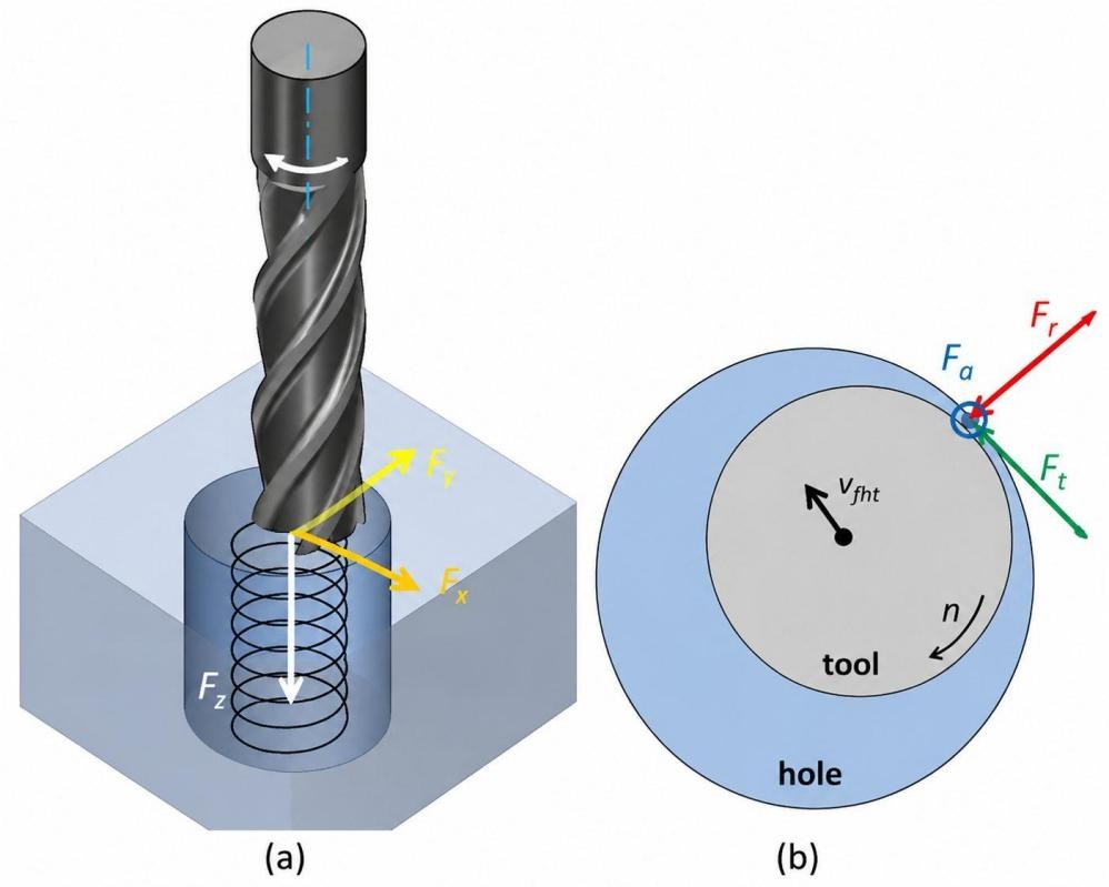
Helical milling process (ScienceDirect)
Helical interpolation is the coordinated CNC motion used to generate the helix. It combines circular interpolation with simultaneous linear movement along the machine's axial axis.
In machining terms, helical milling refers to the operation, while helical interpolation refers to the tool movement programmed by the CNC control. Hole milling is one application of this motion.
How Does Helical Milling Work in CNC?
A CNC helical milling path combines two types of movement. The cutter travels around the programmed circular path while the machine moves the tool along the axial axis. The control keeps these movements synchronized so the cutter follows a continuous helix through the workpiece.
The path can be generated directly by the CNC control from programmed interpolation commands or created by CAM software and then posted as machine code. In either case, the machine must coordinate the circular and axial movements at the same time.
CNC Machine and Control Requirements
The CNC machine needs coordinated motion in the machining plane and along the third axis. For a typical vertical milling machine, circular movement occurs in the X-Y plane while the Z-axis provides the axial movement.
The CNC control must support the required interpolation function and process the programmed axis movements as one coordinated path. CAM software can also calculate the toolpath and output the corresponding axis movements for the machine control.
Circular and Axial Motion
Circular interpolation establishes the cutter's path around the feature center. At the same time, the axial axis moves by a programmed distance.
The machine therefore does not complete the circular movement first and then move axially. Both movements occur together. This coordinated motion is what changes a circular path into a helical path.
Helical Pitch and Toolpath
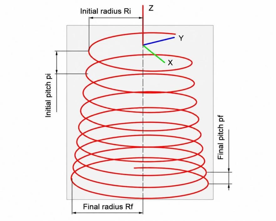
An integrated helical-spiral motion strategy for CNC machining (Springer Nature)
The helical pitch is the axial distance traveled during one complete toolpath revolution. For example, if the tool moves 2 mm along the Z-axis during one full revolution, the helix pitch is 2 mm per revolution.
CAM software can use the required depth and pitch to generate successive helical movements until the programmed depth is reached. The resulting path maintains the circular motion while progressively advancing through the material.
What Is Helical Milling Used For?
Helical milling is commonly selected for circular features that cannot be produced directly with the available milling cutter. A typical example is a 25 mm hole machined with a 10 mm end mill. The cutter does not need to match the finished hole diameter because the CNC path establishes the required diameter around the tool.
This makes helical milling particularly useful for hole making and hole enlargement. It can also be applied to counterbores and circular pockets where the feature requires a controlled circular path combined with movement in depth.
Helical milling is one of several CNC milling strategies used for producing specific part features. Understanding how it differs from other approaches, such as face milling, end milling, slot milling, and profile milling, helps determine the right machining method for each geometry.
Hole Making and Hole Enlargement
A drilled hole and a helically milled hole are produced differently. With helical milling, the cutter establishes the finished diameter through its centerline path. This is useful when the required hole size is not available as a standard cutter diameter.
For example, a 12 mm end mill can be programmed to produce a 30 mm hole by positioning the cutter at the required radial distance from the hole center. The tool then follows the circular path while progressing through the material.
The same approach can be used to enlarge an existing hole. The initial hole provides clearance for the cutter, while the interpolation path removes material from the remaining wall. This is useful when a drilled pilot hole is smaller than the specified finished diameter.
For a machined hole that carries a dimensional or geometric requirement, the programmed toolpath establishes the nominal diameter, while the final result still depends on the actual machine motion, tool condition, workholding, and inspection of the finished feature.
Circular Pockets and Counterbores
Helical milling can produce a circular pocket when the feature requires a defined diameter and depth rather than a through-hole. The cutter progresses through successive axial levels while maintaining the programmed circular boundary.
A counterbore is a more specific case. Counterbores can be produced by helical interpolation or circular pocketing strategies depending on the feature size, depth, and tooling approach. A counterbore is a cylindrical recess used to provide clearance for a fastener head. It may be machined around an existing hole or created as part of the feature sequence depending on the drawing requirements. The toolpath establishes the counterbore diameter and moves to its specified depth without removing the material below the counterbore floor.
The machining sequence therefore differs from simple hole enlargement. In a counterbore, the existing hole remains as the smaller opening, while the helical operation produces the larger recess around it.
Thread Milling and Other Related Applications
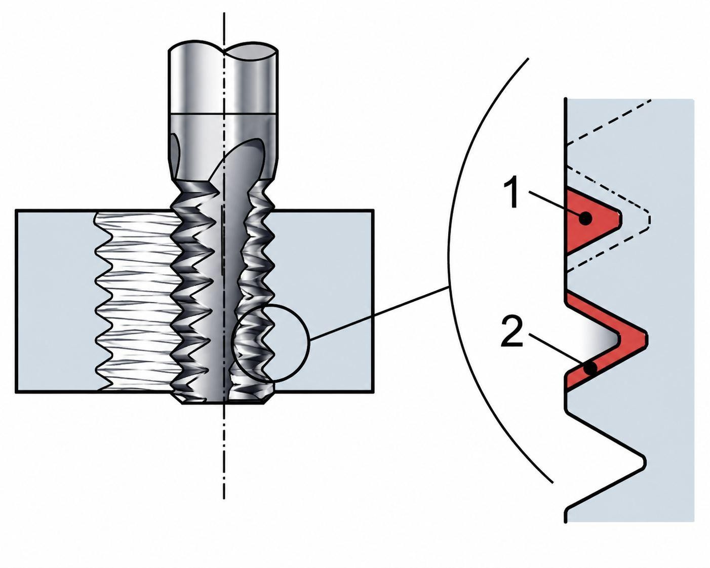
Thread Milling (Sandvik Coromant)
Unlike hole milling, thread milling must synchronize axial movement with the specified thread pitch to generate the correct thread profile.
For example, an internal thread mill may enter a prepared hole below the minor diameter, move to the programmed thread position, and follow a helical path for the required number of revolutions. The toolpath is therefore based on the thread geometry rather than simply producing a cylindrical wall.
Thread milling should not be treated as ordinary hole milling with a different cutter. The cutter geometry, programmed diameter, axial movement, and thread lead all have to correspond to the specified thread.

Precision CNC Machining Service
Need helical milling for a specific part feature? JLCCNC can review your drawing requirements and machining conditions to determine a suitable CNC process. Upload your CAD file for a machining quote.
Helical Milling Geometry and Calculations
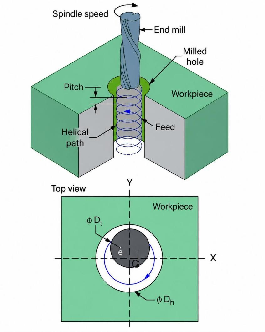
Helical milling process kinematics (ResearchGate)
The geometry of a helical milling operation starts with three dimensions: the finished hole diameter, cutter diameter, and cutter-center path diameter. These dimensions determine where the tool center must travel to produce the required hole.
The axial movement is defined separately by the helical pitch. This describes how far the cutter moves along the Z-axis during one complete revolution. Together, the radial and axial dimensions define the actual helical toolpath.
Cutter Diameter and Tool-Center Path
In helical milling, the cutter does not follow the finished hole diameter directly. Instead, the CNC control positions the tool center at an offset from the hole center.
For an internal circular feature:
Tool-center path diameter = Finished hole diameter − Cutter diameter
For example, a 10 mm end mill machining a 30 mm hole requires a 20 mm tool-center path diameter:
30 mm − 10 mm = 20 mm
The cutter center therefore moves on a 10 mm radius circle around the hole axis. Any error in this programmed position directly affects the final hole size, which is why tool diameter compensation, runout, and machine positioning accuracy must be considered during production machining.
CAM software normally calculates this offset automatically from the selected cutter and feature geometry. Manual programming requires the same relationship to be calculated before entering the interpolation coordinates.
Helical Pitch and Ramping Angle
Helical pitch is the axial distance traveled by the tool during one complete revolution.
If the cutter moves 2 mm in Z during one revolution, the helical pitch is:
Pitch = 2 mm/revolution
For a total machining depth of 10 mm, five revolutions would be required at that constant pitch:
Number of revolutions = 10 ÷ 2 = 5 revolutions
The ramping angle describes the inclination of the helical path relative to the machining plane. For a circular path with radius R and axial movement P per revolution, the angle can be expressed as:
$\theta = \tan^{-1}(P \div 2\pi R)$
Here, P is the axial movement per revolution, and $2\pi R$ is the horizontal distance traveled during one revolution.
The resulting angle is a geometric description of the helix. It should not be treated as a universal machining limit because the suitable path depends on the cutter geometry, workpiece material, machine, and manufacturer's recommendations.
Helical Milling Calculation Example
A CNC mill is programmed to produce a 30 mm diameter hole using a 10 mm end mill. The machining depth is 10 mm, and the programmed pitch is 2 mm per revolution.
The cutter-center path diameter is:
30 mm − 10 mm = 20 mm
The cutter follows this circular path while moving 2 mm downward during each revolution.
The required number of revolutions is:
10 mm ÷ 2 mm/revolution = 5 revolutions
In practice, the programmed toolpath only defines the theoretical geometry. The final hole size is also affected by tool runout, cutter wear, machine accuracy, and cutting conditions.
Helical Milling vs. Drilling: Which Should You Use?
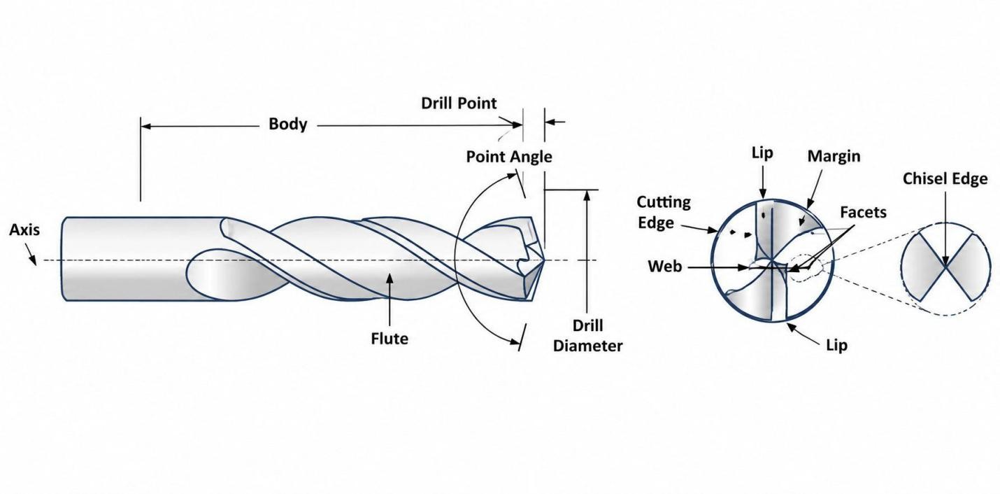
CNC drill geometries (Harvey Performance Company)
For a standard hole, drilling is usually the simpler process. Helical milling is useful for large holes, hole enlargement, and different hole sizes with the same cutter.
Drilling is generally an optimal choice for repeated holes of a fixed diameter, especially in higher-volume work. On the other hand, helical milling is more useful when the hole diameter is larger than the available cutter, an existing hole must be enlarged, and several hole sizes need to be produced with the same milling cutter.
The suitable method depends on the hole size, depth, tolerance requirement, and production quantity.
| Helical Milling | Drilling | |
|---|---|---|
| Hole diameter | Cutter diameter < finished hole diameter | Drill diameter ≈ finished hole diameter |
| Hole enlargement | Suitable | Not typical |
| Large holes | Small/medium cutter can generate a larger diameter | Requires a large-diameter drill |
| Tool diameter | One cutter can produce multiple hole sizes | Different hole sizes generally need different drills |
| Hole depth | Limited by cutter reach and flute length | Well suited to deep holes with suitable tooling |
| Cutting direction | Radial + axial interpolation | Axial cutting |
| Chip evacuation | Through cutter flutes and coolant flow | Through drill flutes |
| Cycle time | Generally longer path | Generally shorter for repeated holes |
| Hole quantity | Useful for varied hole sizes | Efficient for repeated hole sizes |
| Existing hole | Can enlarge | Not normally used for enlargement |
| Machine motion | X-Y circular + Z-axis movement | Spindle rotation + axial feed |
| Typical operation | Hole milling, enlargement, counterbore | Through-hole, blind-hole drilling |
Helical Milling Tools and Cutting Parameters
The cutter diameter establishes the available interpolation range, while flute length and tool projection set the practical depth of the operation. These dimensions should be checked against the finished hole before the toolpath is created.
Cutting conditions are then taken from the cutter manufacturer's data for the workpiece material. Helical pitch and radial engagement should be treated as part of that same toolpath calculation rather than selected as independent values.
Choosing a Tool for Helical Milling
The cutter has to fit inside the finished feature and still leave enough radial movement for interpolation. For an internal hole, a 12 mm cutter cannot produce a 10 mm hole by helical interpolation because the cutter itself is already larger than the finished diameter.
The opposite case is what makes the process useful. A 12 mm cutter can generate a 30 mm hole, with the tool center following an 18 mm diameter path. The cutter diameter and finished diameter therefore need to be established before programming the interpolation path.
Cutter geometry should also match the material being cut. A tool intended for aluminum may have a different flute design from one intended for stainless steel, even when both tools have the same nominal diameter.
Minimum Hole Diameter and Tool Reach
For internal helical milling, the cutter diameter sets the practical lower limit of the hole size because the tool must rotate while maintaining clearance from the finished wall.
Tool reach becomes a separate issue once the hole gets deeper. Consider a 30 mm deep hole using a cutter with a 20 mm cutting length. The tool cannot simply be programmed to the full depth because the required cutting edge is not available through the complete path.
The holder also has to clear the workpiece at the programmed depth. Therefore, the usable tool length is determined by the feature depth and access condition, not by selecting the longest cutter available.
Feed, Speed, and Cutter Engagement
The spindle speed and feed should be taken from the tool manufacturer's data for the selected cutter and material. They should not be transferred directly from a drilling operation because the cutter is engaged differently during interpolation.
Consider the same 12 mm cutter producing a 30 mm hole. The 18 mm tool-center path determines the radial position of the cutter. If the programmed path is changed, the cutter engagement and finished diameter change with it.
The axial engagement comes from the helix. With a pitch of 1.5 mm/revolution, the cutter advances 1.5 mm during each complete revolution. At 2 mm/revolution, the axial advance is greater. Which value is appropriate depends on the cutter manufacturer's application data and the actual workpiece.
Tool Rigidity and Holder Stability
Tool projection should be considered against the required hole depth. A cutter extending well beyond the holder has a different cutting condition from the same cutter used with a short projection.
For example, a 50 mm projection used to machine a 10 mm deep hole leaves considerably more unsupported length than the feature requires. That extra projection does not contribute to the hole geometry; it increases the portion of the tool exposed to cutting forces.
The holder, therefore, forms part of the machining setup. A short, rigid tool assembly is preferable when the feature permits it. For deep holes, the required reach has to be balanced against the cutter's available rigidity and the manufacturer's recommended application limits.
Note
In production machining, helical milling is often selected when a part requires several hole sizes but the available tooling cannot justify dedicated drills for each diameter.
Helical Milling Accuracy and Common Problems and Solutions
Problems in a helically milled hole should be identified from the measured feature and the condition of the cut. Hole size, roundness, wall finish, and tool condition can point toward different causes.
Hole Diameter, Roundness, and Surface Finish
If the finished diameter is consistently above or below the programmed size, check the toolpath and tool condition first. If the diameter changes at different positions around the hole, inspect the cutter runout, toolholder, and machine setup.
Poor roundness can appear when the cutter does not maintain a consistent position during interpolation. Chatter leaves a different signature: visible repeating marks on the whole wall, often accompanied by an uneven finish.
Surface marks can also result from chip recutting. In a deep hole, chips trapped between the cutter and the wall can scratch the finished surface instead of leaving a clean cut.
Tool Deflection and Runout
Long tool projection increases the amount the cutter can move away from its programmed path under cutting force. This can produce an undersized or oversized section of the hole rather than a uniform dimensional error.
Runout produces uneven cutting around the circumference. One cutting edge may remove more material than the others, leaving variation in the wall and accelerating wear on the loaded edge.
If the measured diameter changes around the hole, checking runout at the tool before changing the CNC program is a useful first step.
Chip Evacuation and Tool Wear
Chips that remain in the hole can be cut again during the next revolution. The result may be a poor surface finish, increased cutting load, and damage to the cutting edges.
Tool wear becomes more significant as the operation continues. A worn cutter can shift the finished diameter and leave a different wall finish from a new tool.
If several symptoms appear together—such as increasing diameter, worsening surface finish, and visible edge wear—the cutter condition should be checked before changing the programmed geometry.
For diagnosis, separate the symptom from the cause: measure the hole, inspect the wall, check the cutter and holder, then examine chip evacuation. This avoids correcting the CNC path for a problem caused by the cutting setup.
Helical Milling FAQs
Q: Can Helical Milling Create a Hole Larger Than the Cutter Diameter?
The cutter follows a larger circular path around the hole's center, so the finished hole can be larger than the cutter itself. For example, a 10 mm end mill can machine a 20 mm hole by using the correct tool-center path.
Q: Is Helical Milling the Same as Helical Interpolation?
The two terms describe closely connected parts of the process. Helical milling refers to the machining operation, while helical interpolation refers to the coordinated circular and axial movement programmed by the CNC control.
Q: Does Helical Milling Require a 3-Axis CNC Machine?
A standard 3-axis CNC milling machine can perform basic helical milling because the operation requires circular movement in two axes and simultaneous axial movement in the third. Additional axes become relevant for more complex feature orientations.
Q: How Deep Can You Helically Mill a Hole?
The usable depth depends on the cutter's cutting length, tool reach, holder clearance, tool rigidity, hole geometry, workpiece material, and manufacturer recommendations. A deeper hole generally requires a tool assembly capable of reaching the required depth without excessive projection.
Q: What Materials Can Be Machined With Helical Milling?
The process can be applied to materials such as aluminum, carbon steel, stainless steel, cast iron, and engineering alloys. Cutter geometry and cutting conditions should be selected for the specific material and tool.
Q: When Is Helical Milling Not the Best Choice?
For large batches of identical holes, drilling can provide a shorter machining cycle and dedicated tooling for the required diameter. Drilling can also be more suitable for deep holes where chip evacuation and tool reach favor a dedicated drill.
Precision CNC Machining Service
Professional manufacturing, fast turnaround, and quality assurance.
Conclusion: When to Use Helical Milling
Helical milling is a practical option for producing circular features with a milling cutter. It is particularly useful for large holes, hole enlargements, circular pockets, and counterbores where the required diameter exceeds the cutter diameter.
The process also gives the CNC programmer control over the tool-center path, hole diameter, axial movement, and machining depth. These relationships should be checked before the toolpath is created.
For repeated holes of the same diameter, drilling is often the simpler choice. Helical milling becomes more suitable when the part requires different hole sizes, an existing hole must be enlarged, or a large circular feature needs to be produced without a matching-size drill.
JLCCNC provides CNC machining for components requiring accurate holes, bores, pockets, counterbores, and other interpolated features. The machining process can be selected according to the drawing, material, feature size, and production requirements.
Upload your CAD file to let JLCCNC review hole features, tolerances, materials, and machining requirements for a CNC machining quote.
Keep Learning
What Are Secondary Operations in Manufacturing?
Key Takeaways Secondary operations refine a part after its main production stage. Their classification depends on the production route. Typical tasks include machining, heat treatment, finishing, joining, and marking. Final drawing requirements help determine which added steps are needed. Extra stages can influence cost, lead time, handling, and inspection. Secondary operations are additional manufacturing steps performed after an earlier production stage to bring a part to its required final conditio......
What Is EDM? How Electrical Discharge Machining Works
What Is EDM (Electrical Discharge Machining)? How It Works & Applications A mold shop needs to cut a cavity into hardened tool steel — the kind of material that would dull a carbide end mill before the cut is even halfway done. A medical device maker needs a slot 0.05mm wide in a titanium component, thinner than most drill bits can even produce. Neither job is solvable with a spinning cutting tool, because the material is either too hard, the geometry too fine, or both. That's the gap EDM was built to......
Wire EDM Machine: Types, Specs & How to Choose One
Wire EDM Machine: Types, Specs & How to Choose One Our guide on how EDM wire cutting works covers the process itself — the spark erosion, the dielectric fluid, the tolerances the technique can hold. This one is about the machine that runs that process: what actually differentiates one wire EDM machine from another, and what matters when you're evaluating or specifying one. 💡 Need Precision Wire EDM Services? Understanding machine specs is crucial, but actually running them takes experience. At JLCCNC......
Titanium CNC Machining: Properties, Challenges & Best Practices
Titanium CNC Machining: Properties, Challenges & Best Practices A shop that's comfortable machining aluminum all day can still get caught off guard the first time a titanium job comes through. The part looks the same on the CAD screen, the toolpath strategy looks reasonable, and then the tool overheats, work-hardens the surface it just cut, and the finish comes out nothing like what aluminum would have produced at the same settings. Titanium isn't just "harder aluminum" — it behaves differently enough......
High Volume CNC Machining: What Changes When You Scale Production
High Volume CNC Machining: What Changes When You Scale Production Ten prototypes and ten thousand production parts are not the same problem wearing different clothes. A process that works fine for a handful of pieces — a bit of manual deburring here, a quick visual check there, tooling that gets swapped whenever it feels a little dull — falls apart the moment volume multiplies by a thousand. High volume CNC machining isn't just "the same thing, more of it." It's a different set of priorities, where de......
PTFE CNC Machining: Properties, Applications & Best Practices
PTFE CNC Machining: Properties, Applications & Best Practices PTFE — better known by the DuPont trade name Teflon — is a strange material to put on a CNC machine. It's soft, it barely holds a sharp edge itself, and it deforms under clamping pressure in ways that would ruin tolerance on almost any other engineering plastic. And yet it gets machined constantly, because nothing else offers PTFE's combination of an almost unbelievably low coefficient of friction and near-universal chemical resistance. Mac......